EP1538266A1 - Lärmschutzwandelement - Google Patents
Lärmschutzwandelement Download PDFInfo
- Publication number
- EP1538266A1 EP1538266A1 EP04027597A EP04027597A EP1538266A1 EP 1538266 A1 EP1538266 A1 EP 1538266A1 EP 04027597 A EP04027597 A EP 04027597A EP 04027597 A EP04027597 A EP 04027597A EP 1538266 A1 EP1538266 A1 EP 1538266A1
- Authority
- EP
- European Patent Office
- Prior art keywords
- noise protection
- edge
- wall
- insulating
- element according
- Prior art date
- Legal status (The legal status is an assumption and is not a legal conclusion. Google has not performed a legal analysis and makes no representation as to the accuracy of the status listed.)
- Granted
Links
- 238000009413 insulation Methods 0.000 claims abstract description 40
- 238000009423 ventilation Methods 0.000 claims abstract description 31
- 125000006850 spacer group Chemical group 0.000 claims description 55
- 239000002023 wood Substances 0.000 claims description 12
- 238000005273 aeration Methods 0.000 claims description 6
- 239000004033 plastic Substances 0.000 claims description 6
- 239000002184 metal Substances 0.000 claims description 4
- 230000004888 barrier function Effects 0.000 description 13
- 238000010521 absorption reaction Methods 0.000 description 5
- 230000000694 effects Effects 0.000 description 3
- XLYOFNOQVPJJNP-UHFFFAOYSA-N water Substances O XLYOFNOQVPJJNP-UHFFFAOYSA-N 0.000 description 3
- 230000015572 biosynthetic process Effects 0.000 description 2
- 239000011490 mineral wool Substances 0.000 description 2
- 239000003795 chemical substances by application Substances 0.000 description 1
- 238000010276 construction Methods 0.000 description 1
- 210000004013 groin Anatomy 0.000 description 1
- 238000009434 installation Methods 0.000 description 1
- 230000007774 longterm Effects 0.000 description 1
- 239000000463 material Substances 0.000 description 1
- 230000000149 penetrating effect Effects 0.000 description 1
- 239000003755 preservative agent Substances 0.000 description 1
Images


Classifications
-
- E—FIXED CONSTRUCTIONS
- E01—CONSTRUCTION OF ROADS, RAILWAYS, OR BRIDGES
- E01F—ADDITIONAL WORK, SUCH AS EQUIPPING ROADS OR THE CONSTRUCTION OF PLATFORMS, HELICOPTER LANDING STAGES, SIGNS, SNOW FENCES, OR THE LIKE
- E01F8/00—Arrangements for absorbing or reflecting air-transmitted noise from road or railway traffic
- E01F8/0005—Arrangements for absorbing or reflecting air-transmitted noise from road or railway traffic used in a wall type arrangement
- E01F8/0047—Arrangements for absorbing or reflecting air-transmitted noise from road or railway traffic used in a wall type arrangement with open cavities, e.g. for covering sunken roads
- E01F8/0052—Grate-style, e.g. as wall facing
- E01F8/0058—Grate-style, e.g. as wall facing with damping material, e.g. rockwool, sand
Definitions
- the invention relates to a noise barrier wall element with a front wall, a spaced from the front wall rear wall and at least one arranged between the front wall and the rear wall, preferably plate-shaped, insulating element.
- noise barrier elements composed, which are positioned so that the, z. B. in the area of Driveway, highway o. The like., Sound produced on the front wall and hits is substantially absorbed by the underlying insulating element.
- the front wall may be formed so that there as well still a sound reflection takes place.
- the front wall forming the sound entrance side has one Battens on, but may alternatively be closed while the side facing away from sound usually from a groove and Spring wall exists.
- the front wall and the rear wall usually by horizontally extending, strip-shaped bars rigid connected to each other, which take over the wind load.
- the insulating elements consist of mineral wool slabs.
- At least one the front wall and the rear wall connecting with each other and at a distance holding first latch is provided on which the insulating element with his first edge is characterized by the fact that the Ventilation means at least one between the first bar and the first Have edge of the insulating element seated spacer means, the like is formed and arranged that at least partially the first Edge of the insulating element is exposed to aeration. It can be act at the first edge of the Dämmimplantations around its lower edge.
- the aeration means can be at least one between a second Latch and a second edge of the insulating element sitting further Have spacer means which is formed and arranged that at least in sections, the second edge of the insulating element of a Ventilation is exposed. It may be at this second edge of the Dämmimplantations act around its upper edge.
- the latter two preferred embodiments may also be combined with each other by the insulating element at a distance of the front wall and / or the rear wall fixing spacer means on the sitting between a bar and an edge of the insulating element Spacer is attached and the insulating element with its edge on the the insulating element at a distance from the front wall and / or the rear wall abuts fixing spacer.
- a structurally particularly simple solution can be achieved in that the at least one spacer means of a bar, preferably made of wood or plastic.
- At least one Spacer made of a profiled sheet metal, preferably of metal or plastic, train.
- the Profile sheet at least one support leg and a recess for receiving have the corresponding edge of the insulating element.
- the profile sheet with two support legs, between which the recess is formed.
- the spacer should be perforated be. Such an embodiment is particularly suitable when the Spacer extends over a greater length and in particular from a continuous bar exists.
- the ventilation means may also provided in the insulating element, preferably round and / or slit-shaped, openings are formed, through the air entering and exiting can.
- the ventilation means may also provided in the insulating element, preferably round and / or slit-shaped, openings are formed, through the air entering and exiting can.
- the Absorption performance can be increased.
- a plurality of insulating elements each at a distance from each other, whereby the Ventilation agent from the spaces between the insulation elements are formed.
- the insulation boards are essentially in a common plane, whereby the spaces between them Edges arise. This version is optional with the previously described embodiments combined.
- the aeration means may also be corrugated or grooved be formed, at least in sections on the side of a Element is formed, which at least on a portion of a other element substantially touching.
- the aeration means takes over Corrugation or grooving the function of the above-described.Distanzstoff, so that between the individual formed by the corrugation or grooving Elevations or projections in each case an air duct or air gap to Achieving sufficient ventilation is formed.
- Noise protection wall elements described in more detail wherein like parts are consistently marked with the same reference numerals.
- the Noise protection wall elements described below are used to build used by noise barriers by the noise barrier elements strung together.
- FIGs 1 to 3 is a noise barrier wall element 1 in a first Embodiment shown and has in the illustrated embodiment a Front wall 2, a lower latch 3a, a middle latch 3b, a upper latch 3c, two insulation boards 4a and 4b and a rear wall 5 on.
- the front wall 2 is the sound source, z. B. a street, facing and in the illustrated embodiment consists of spaced apart vertical slats.
- the rear wall 5 accordingly forms the soundproof side and can be closed and in particular off consist of a groove and spring wall.
- the bars 3a to 3c form in illustrated embodiment, horizontal strips, where the Front wall 2 and the rear wall 5 are fixed, and thus also serve as Spacer between the front wall 2 and the rear wall 5.
- a cavity formed in the illustrated embodiment by the middle bar 3b is divided into an upper and a lower cavity, wherein in lower cavity a first insulating plate 4a and in the upper cavity a second insulation board 4 b is arranged.
- the lower insulation board 4a is between the lower latch 3a and the middle latch 3b and the upper one Insulating board 4b between the middle latch 3b and the upper latch 3c fixed.
- the lower insulation board 4a is supported by its lower edge 4aa on the lower latch 3a from, as Figure 3 reveals.
- the lattice existing front wall 2, the Insulating boards 4a, 4b and the rear wall 5 are vertical in the installed position arranged and therefore have a constant distance over the height to each other. It follows that the lower edges of the insulation boards 4a, 4b are aligned horizontally.
- the lower and middle latches 3a and 3b have at their upper side respectively a slightly inclined to the front wall 2 down surface, as shown in FIG 3 is shown by way of example with respect to the surface 3aa of the lower latch 3a is. Due to the inclined relative to the horizontal arrangement of the Surface of the lower and middle latches 3a and 3b is achieved in that the noise barrier wall element penetrating water in the direction of the inclination the surface of the bolt 3a, 3b can drain again.
- the existing of the battens front wall 2, the bars 3a to 3c and the Rear wall 5 consist in the illustrated embodiment of wood, while the insulation boards 4a, 4b are formed of mineral wool boards.
- FIG. 1 is a variety of Spacers provided on the lower latch 3a, both sides on middle latch 3b and arranged on the underside of the upper latch 3c are and where the insulation boards 4a and 4b with their respective support adjacent edge.
- Figure 3 is an example of the arrangement of a such spacer 6 on the inclined top surface 3aa of the lower Riegel 3a and the arrangement of the lower insulating plate 4a with her bottom edge 4aa shown on the top of the spacer 6.
- the spacers 6 are shown in FIG Embodiment a rectangular cross-section. Because of the inclined Arrangement of the top 3aa of the lower bolt 3a is also the surface of Top 6a of the spacers 6 correspondingly inclined. This leads to the insulation board 4a only with the rear end 5 facing the rear end lower edge 4aa rests on the spacers 6 and between the lower edge 4aa of the insulating board 4a and the upper side 6a the spacers 6 creates a gap 8 opening towards the front wall 2, as Figure 3 also shows. This gap 8 does not allow only one free drainage, but also ventilation in particular of the lower Edge 4aa of the insulation board 4a.
- the spacers 6 usually exist from groin pieces.
- FIGS. 2 and 3 also show, they are shown in FIG first embodiment, the insulation boards 4a and 4b directly to the Front wall 2, while they are arranged to the rear wall 5 at a distance are, so that between the insulation boards 4a, 4b on the one hand and the rear wall 5 on the other hand, a cavity 9a is formed.
- a further spacer 7a on the spacer. 6 is fixed and on which the insulation board 4 a with its rear wall. 5 facing rear side. In this way, the insulation board 4a wedged between the front wall 2 and the spacer 7a.
- the Spacer 7a for example, from a consistently horizontal extending bar or from spaced strip pieces consist.
- a second embodiment shown in Figure 4 differs from the first embodiment according to Figures 1 to 3, characterized in that the Insulating panels are installed at a distance from the front wall 2.
- a further spacer 7b is provided, the between the front wall 2 and the insulation board 4a on the spacer. 6 is attached and doing both the front wall 2 and the insulation board. 4 touched, so that in the illustrated second embodiment of FIG. 4 the depth of the second cavity 9b about the width of the spacer 7b is determined.
- This spacer 7b is shown in the Embodiment rectangular and can optionally consist of a continuous Bar or consist of several spaced apart Leisten brainstormen be formed.
- the two support legs 26a, 26b serve to support or support the profile sheet 26 on the top 3aa of the bolt 3a and are dimensioned in terms of length and inclination, that on the one hand, the recess 26c for receiving the lower edge 4aa the insulating board 4a receives its horizontal orientation and the other the the insulation board 4 a at a distance from the front wall 2 and the rear wall. 5 to form the previously described cavities 9a and 9b is arranged.
- the Support legs 26a, 26b with their lower ends not only on the top 3aa of the bolt 3a, but also on the insides of the front wall. 2 and the rear wall 5, as shown in FIG. 6.
- the profile sheets according to the third described with reference to FIG Design can be designed as smooth sheets. In such a case however, it is then necessary to have a large number of individual short ones Provide Pröfilblechen, in the longitudinal direction of the latch 3a to 3c in Distance from each other are installed, between each one for to form the ventilation necessary air gap.
- the profile sheets with a in the figures not provided perforation to allow the ventilation effect or even increase.
- the education of a Perforation also has the advantage that the pressure on the insulation boards 4a, 4b is not increased.
- FIG. 7 shows a fourth embodiment in which instead of closed insulation boards, which in the previously described Versions are used, .Dämmplatten 24a, 24b with a perforation are provided, through which the air can enter and exit.
- the perforation the is not specified in Figure 7, may have round holes, such as figure 7 reveals. Alternatively, it is also conceivable, the holes as slots perform. By the hole can also, if necessary, also the sound absorption performance of the insulation boards 24a, 24b are increased.
- FIG. 7 illustrated perforated insulation panels 24a, 24b, of course, for the first to third embodiments according to the figures 1 to 6 instead of there shown closed insulation boards 4a, 4b can be used.
- the insulation boards 4a, 4b and 24a, 24b to divide into a plurality of sub-plates, which at a distance are installed from each other, so that between the individual insulation boards further air gaps or cavities arise.
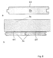
- FIG 8 is an example of the formation of such a corrugation or Nutung 46 at the voltage applied to the latch 3a inside. of the Rear wall 5 forming rear wall panels 5a, wherein in Figure 8a a single back panel 5a increases in cross section and in figure 8b partial arrangement of two by a tongue and groove training interconnected rear wall panels 5a on the latch 3a reduced in Cross section is shown.
- the runs Corrugation or grooving 46 in the longitudinal direction of the rear wall panels 5a and thus in installation position in the vertical direction.
- Corrugation or grooving in a different orientation for example in horizontal orientation.
- the corrugation or groove 46 can Furthermore, to a slight improvement of Lead to sound absorption properties.
- such corrugation or grooving on others as the components shown in Figure 8 such as at Inside the battens of the front wall 2 or on the bars 3a to 3c and in combination with the previously described ventilation measures can be provided.
Landscapes
- Engineering & Computer Science (AREA)
- Architecture (AREA)
- Civil Engineering (AREA)
- Structural Engineering (AREA)
- Building Environments (AREA)
Abstract
Description
Claims (17)
- Lärmschutzwandelement mit einer Vorderwand (2) , einer von der Vorderwand (2) beabstandeten Rückwand (5) und mindestens einem zwischen der Vorderwand (2) und der Rückwand (5) angeordneten, vorzugsweise plattenförmigen, Dämmelement (4a, 4b; 24a, 24b),
gekennzeichnet durch Belüftungsmittel für eine zumindest abschnittsweise Belüftung der Dämmplatte (4a, 4b; 24a, 24b) zur Ableitung von Feuchtigkeit. - Lärmschutzwandelement nach Anspruch 1,
dadurch gekennzeichnet, dass die Belüftungsmittel mindestens ein das Dämmelement (4a, 4b) im Abstand von der Vorderwand (2) und/oder der Rückwand (5) fixierendes Distanzmittel (7a; 7b) aufweisen. - Lärmschutzwandelement nach Anspruch 2, mit mindestens einem die Vorderwand (2) und die Rückwand (5) miteinander verbindenden und auf Abstand haltenden ersten Riegel (3a),
dadurch gekennzeichnet, dass das mindestens eine Distanzmittel (7a; 7b) am ersten Riegel (3a) befestigt ist und das Dämmelement (4a) am Distanzmittel (7a; 7b; 26) anliegt. - Lärmschutzwandelement nach mindestens einem der vorangegangenen Ansprüche, mit mindestens einem die Vorderwand (2) und die Rückwand (5) miteinander verbindenden und auf Abstand haltenden ersten Riegel (3a), an dem das Dämmelement (4a) mit seinem ersten Rand (4aa) abgestützt ist,
dadurch gekennzeichnet, dass die Belüftungsmittel mindestens ein zwischen dem ersten Riegel (3a) und dem ersten Rand (4aa) des Dämmelementes (4a) sitzendes Distanzmittel (6; 26) aufweisen, das so ausgebildet und angeordnet ist, dass zumindest abschnittsweise der erste Rand (4aa) des Dämmelementes (4a) einer Belüftung ausgesetzt ist. - Lärmschutzwandelement nach Anspruch 4,
dadurch gekennzeichnet, dass der erste Rand (4aa) des Dämmelementes (4a) dessen unterer Rand ist. - Lärmschutzwandelement nach Anspruch 4 oder 5, mit mindestens einem die Vorderwand (2) und die Rückwand (5) miteinander verbindenden und auf Abstand haltenden zweiten Riegel (3b), an dem das Dämmelement (4a) mit seinem zweiten Rand abgestützt ist,
dadurch gekennzeichnet, dass die Belüftungsmittel mindestens ein zwischen dem zweiten Riegel (3b) und dem zweiten Rand des Dämmelementes (4a) sitzendes weiteres Distanzmittel aufweisen, das so ausgebildet und angeordnet ist, dass zumindest abschnittsweise der zweite Rand des Dämmelementes (4a) einer Belüftung ausgesetzt ist. - Lärmschutzwandelement nach den Ansprüchen 5 und 6,
dadurch gekennzeichnet, dass der zweite Rand des Dämmelementes (4a) dessen oberer Rand ist. - Lärmschutzwandelement nach Anspruch 2 sowie nach mindestens einem der Ansprüche 4 bis 7,
dadurch gekennzeichnet, dass das das Dämmelement (4a) im Abstand von der Vorderwand (2) und/oder der Rückwand (5) fixierende Distanzmittel (7a; 7b) auf dem zwischen dem Riegel (3a) und dem entsprechenden Rand (4aa) des Dämmelementes (4a) sitzenden Distanzmittel (6) befestigt ist und das Dämmelement (4a) mit seinem entsprechenden Rand (4aa) an dem das Dämmelement (4a) im Abstand von der Vorderwand (2) und/oder der Rückwand (5) fixierenden Distanzmittel (7a; 7b) anliegt. - Lärmschutzwandelement nach mindestens einem der Ansprüche 2 bis 8,
dadurch gekennzeichnet, dass das mindestens eine Distanzmittel (6; 7a; 7b) aus einer Leiste, vorzugsweise aus Holz oder Kunststoff, besteht. - Lärmschutzwandelement nach mindestens einem der Ansprüche 2 bis 8,
dadurch gekennzeichnet, dass das mindestens eine Distanzmittel aus einem Profilblech (26), vorzugsweise aus Metall oder Kunststoff, besteht. - Lärmschutzwandelement nach den Ansprüchen 4 und 10,
dadurch gekennzeichnet, dass das Profilblech (26) mindestens einen Stützschenkel (26a; 26b) und eine Vertiefung (26c) zur Aufnahme des Randes (4aa) des Dämmelementes (4a) aufweist. - Lärmschutzwandelement nach Anspruch 11,
dadurch gekennzeichnet; dass das Profilblech (26) zwei Stützschenkel (26a, 26b) aufweist, zwischen denen die Vertiefung (26c) ausgebildet ist. - Lärmschutzwandelement nach mindestens einem der Ansprüche 2 bis 12,
dadurch gekennzeichnet, dass das Distanzmittel gelocht ist. - Lärmschutzwandelement nach mindestens einem der Ansprüche 2 bis 13,
gekennzeichnet durch eine Mehrzahl von voneinander beabstandeten Distanzmitteln. - Lärmschutzwandelement nach mindestens einem der vorangegangenen Ansprüche,
dadurch gekennzeichnet, dass die Belüftungsmittel von im Dämmelement (24a, 24b), vorgesehenen, vorzugsweise runden und/oder schlitzförmigen, Öffnungen gebildet sind. - Lärmschutzwandelement nach mindestens einem der vorangegangenen Ansprüche, mit mehreren nebeneinander angeordneten Dämmelementen,
dadurch gekennzeichnet, dass die Dämmelemente im Abstand voneinander angeordnet und die Belüftungsmittel von den Zwischenräumen zwischen den Dämmelementen gebildet sind. - Lärmschutzwandelement nach mindestens einem der vorangegangenen Ansprüche,
dadurch gekennzeichnet, dass die Belüftungsmittel von einer Riffelung oder Nutung (46) gebildet sind, die zumindest abschnittsweise an derjenigen Seite eines Elementes ausgebildet ist, die zumindest an einem Abschnitt eines anderen Elementes im Wesentlichen berührend anliegt.
Applications Claiming Priority (2)
| Application Number | Priority Date | Filing Date | Title |
|---|---|---|---|
| DE20318837U DE20318837U1 (de) | 2003-12-02 | 2003-12-02 | Lärmschutzwandelement |
| DE20318837U | 2003-12-02 |
Publications (2)
| Publication Number | Publication Date |
|---|---|
| EP1538266A1 true EP1538266A1 (de) | 2005-06-08 |
| EP1538266B1 EP1538266B1 (de) | 2014-03-12 |
Family
ID=34442551
Family Applications (1)
| Application Number | Title | Priority Date | Filing Date |
|---|---|---|---|
| EP20040027597 Expired - Lifetime EP1538266B1 (de) | 2003-12-02 | 2004-11-19 | Lärmschutzwandelement |
Country Status (2)
| Country | Link |
|---|---|
| EP (1) | EP1538266B1 (de) |
| DE (1) | DE20318837U1 (de) |
Citations (4)
| Publication number | Priority date | Publication date | Assignee | Title |
|---|---|---|---|---|
| DE7210588U (de) * | 1972-06-15 | Roetterink J | Vorgefertigte Schalldämmwand | |
| DE9105831U1 (de) * | 1991-05-10 | 1991-08-08 | Colberg Metall-, Stahl- und Kunststofftechnik GmbH, 3150 Peine | Element einer Lärmschutzwand |
| DE9212668U1 (de) | 1992-09-21 | 1993-01-14 | Josef Schmees GmbH + Co. KG, 4474 Fresenburg | Lärmschutzwand |
| EP0718442A2 (de) * | 1994-12-16 | 1996-06-26 | SAICO S.p.A. | Lärmschutzwand für autobahnen , eisenbahnen und dergleichen |
-
2003
- 2003-12-02 DE DE20318837U patent/DE20318837U1/de not_active Expired - Lifetime
-
2004
- 2004-11-19 EP EP20040027597 patent/EP1538266B1/de not_active Expired - Lifetime
Patent Citations (4)
| Publication number | Priority date | Publication date | Assignee | Title |
|---|---|---|---|---|
| DE7210588U (de) * | 1972-06-15 | Roetterink J | Vorgefertigte Schalldämmwand | |
| DE9105831U1 (de) * | 1991-05-10 | 1991-08-08 | Colberg Metall-, Stahl- und Kunststofftechnik GmbH, 3150 Peine | Element einer Lärmschutzwand |
| DE9212668U1 (de) | 1992-09-21 | 1993-01-14 | Josef Schmees GmbH + Co. KG, 4474 Fresenburg | Lärmschutzwand |
| EP0718442A2 (de) * | 1994-12-16 | 1996-06-26 | SAICO S.p.A. | Lärmschutzwand für autobahnen , eisenbahnen und dergleichen |
Also Published As
| Publication number | Publication date |
|---|---|
| DE20318837U1 (de) | 2005-04-14 |
| EP1538266B1 (de) | 2014-03-12 |
Similar Documents
| Publication | Publication Date | Title |
|---|---|---|
| DE2303879C3 (de) | Schallabsorbierendes Bauelement | |
| DE2935745C2 (de) | Lärmschutzwand | |
| DE60017959T2 (de) | Rolladenkasten, Seitenteil und Abdeckprofil für den Kasten | |
| DE2640910C3 (de) | Als Lärmschutzwand und Leiteinrichtung dienende Schutzwand | |
| DE202008006944U1 (de) | Auflageprofile für rostartige Strukturen, insbesondere für Bodenbeläge und Wandbeläge aus Holz oder Kunststoff | |
| EP1710363B1 (de) | Wandbausystem mit Glasplatten | |
| EP1538266B1 (de) | Lärmschutzwandelement | |
| DE2708095A1 (de) | Verfahren und abstandhalter zum befestigen eines verbundelementes an einer tragkonstruktion | |
| EP1323876B1 (de) | Tafelförmiges Bauelement, dafür geeigneter Abstandshalter und Rippenpaarträger, damit errichtetes Bauwerk und Verfahren zu seiner Errichtung | |
| DE19931810A1 (de) | Trittboden für Balkone, Dachgärten oder dergleichen | |
| CH656413A5 (de) | Wandelement. | |
| DE102004041967B4 (de) | Träger für einen Bodenbelag für Freilandräume | |
| DE102021115733B4 (de) | Raffstorekasten und Verbindungsbeschlag zur Befestigung des Raffstores | |
| CH661086A5 (de) | Auflagekoerper fuer dacheindeckungsplatten. | |
| AT410455B (de) | Holzbautafel und abschluss-profilelement hiefür | |
| EP3733995A1 (de) | Witterungsgeschützte holzboden-vorrichtung | |
| DE9418602U1 (de) | Plattenkonstruktion | |
| EP1995387A2 (de) | Holzbauelement und daraus gebildetes Wandelement | |
| DE2535826C3 (de) | Bauelement fur einen dem Schutz von Personen im Bereich von Baustellen dienenden Fußgängertunnel | |
| DE69005300T2 (de) | Fassadebekleidungseinheit. | |
| DE102021204332A1 (de) | Wärmedämm-Anordnung zur Montage auf einer Gebäudefläche sowie hierfür verwendbare Montage-Leiste | |
| AT399894B (de) | Lärmschutzwand | |
| DE9105295U1 (de) | Profilleiste für Fassadenplatten | |
| DE4419537A1 (de) | Lärmschutzwand | |
| DE202023103080U1 (de) | Lärmschutzelement aus nachwachsenden Rohstoffen |
Legal Events
| Date | Code | Title | Description |
|---|---|---|---|
| PUAI | Public reference made under article 153(3) epc to a published international application that has entered the european phase |
Free format text: ORIGINAL CODE: 0009012 |
|
| AK | Designated contracting states |
Kind code of ref document: A1 Designated state(s): AT BE BG CH CY CZ DE DK EE ES FI FR GB GR HU IE IS IT LI LU MC NL PL PT RO SE SI SK TR |
|
| AX | Request for extension of the european patent |
Extension state: AL HR LT LV MK YU |
|
| 17P | Request for examination filed |
Effective date: 20051208 |
|
| AKX | Designation fees paid |
Designated state(s): AT BE BG CH CY CZ DE DK EE ES FI FR GB GR HU IE IS IT LI LU MC NL PL PT RO SE SI SK TR |
|
| 17Q | First examination report despatched |
Effective date: 20071220 |
|
| GRAP | Despatch of communication of intention to grant a patent |
Free format text: ORIGINAL CODE: EPIDOSNIGR1 |
|
| INTG | Intention to grant announced |
Effective date: 20130926 |
|
| GRAS | Grant fee paid |
Free format text: ORIGINAL CODE: EPIDOSNIGR3 |
|
| GRAA | (expected) grant |
Free format text: ORIGINAL CODE: 0009210 |
|
| AK | Designated contracting states |
Kind code of ref document: B1 Designated state(s): AT BE BG CH CY CZ DE DK EE ES FI FR GB GR HU IE IS IT LI LU MC NL PL PT RO SE SI SK TR |
|
| REG | Reference to a national code |
Ref country code: GB Ref legal event code: FG4D Free format text: NOT ENGLISH |
|
| REG | Reference to a national code |
Ref country code: CH Ref legal event code: EP |
|
| REG | Reference to a national code |
Ref country code: AT Ref legal event code: REF Ref document number: 656435 Country of ref document: AT Kind code of ref document: T Effective date: 20140315 |
|
| REG | Reference to a national code |
Ref country code: IE Ref legal event code: FG4D Free format text: LANGUAGE OF EP DOCUMENT: GERMAN |
|
| REG | Reference to a national code |
Ref country code: DE Ref legal event code: R096 Ref document number: 502004014551 Country of ref document: DE Effective date: 20140417 |
|
| REG | Reference to a national code |
Ref country code: CH Ref legal event code: NV Representative=s name: RENTSCH PARTNER AG, CH |
|
| REG | Reference to a national code |
Ref country code: NL Ref legal event code: VDEP Effective date: 20140312 |
|
| PG25 | Lapsed in a contracting state [announced via postgrant information from national office to epo] |
Ref country code: FI Free format text: LAPSE BECAUSE OF FAILURE TO SUBMIT A TRANSLATION OF THE DESCRIPTION OR TO PAY THE FEE WITHIN THE PRESCRIBED TIME-LIMIT Effective date: 20140312 Ref country code: CY Free format text: LAPSE BECAUSE OF FAILURE TO SUBMIT A TRANSLATION OF THE DESCRIPTION OR TO PAY THE FEE WITHIN THE PRESCRIBED TIME-LIMIT Effective date: 20140312 Ref country code: SE Free format text: LAPSE BECAUSE OF FAILURE TO SUBMIT A TRANSLATION OF THE DESCRIPTION OR TO PAY THE FEE WITHIN THE PRESCRIBED TIME-LIMIT Effective date: 20140312 |
|
| PG25 | Lapsed in a contracting state [announced via postgrant information from national office to epo] |
Ref country code: BG Free format text: LAPSE BECAUSE OF FAILURE TO SUBMIT A TRANSLATION OF THE DESCRIPTION OR TO PAY THE FEE WITHIN THE PRESCRIBED TIME-LIMIT Effective date: 20140612 Ref country code: NL Free format text: LAPSE BECAUSE OF FAILURE TO SUBMIT A TRANSLATION OF THE DESCRIPTION OR TO PAY THE FEE WITHIN THE PRESCRIBED TIME-LIMIT Effective date: 20140312 Ref country code: EE Free format text: LAPSE BECAUSE OF FAILURE TO SUBMIT A TRANSLATION OF THE DESCRIPTION OR TO PAY THE FEE WITHIN THE PRESCRIBED TIME-LIMIT Effective date: 20140312 Ref country code: IS Free format text: LAPSE BECAUSE OF FAILURE TO SUBMIT A TRANSLATION OF THE DESCRIPTION OR TO PAY THE FEE WITHIN THE PRESCRIBED TIME-LIMIT Effective date: 20140712 Ref country code: RO Free format text: LAPSE BECAUSE OF FAILURE TO SUBMIT A TRANSLATION OF THE DESCRIPTION OR TO PAY THE FEE WITHIN THE PRESCRIBED TIME-LIMIT Effective date: 20140312 |
|
| PG25 | Lapsed in a contracting state [announced via postgrant information from national office to epo] |
Ref country code: PL Free format text: LAPSE BECAUSE OF FAILURE TO SUBMIT A TRANSLATION OF THE DESCRIPTION OR TO PAY THE FEE WITHIN THE PRESCRIBED TIME-LIMIT Effective date: 20140312 Ref country code: SK Free format text: LAPSE BECAUSE OF FAILURE TO SUBMIT A TRANSLATION OF THE DESCRIPTION OR TO PAY THE FEE WITHIN THE PRESCRIBED TIME-LIMIT Effective date: 20140312 Ref country code: ES Free format text: LAPSE BECAUSE OF FAILURE TO SUBMIT A TRANSLATION OF THE DESCRIPTION OR TO PAY THE FEE WITHIN THE PRESCRIBED TIME-LIMIT Effective date: 20140312 |
|
| REG | Reference to a national code |
Ref country code: DE Ref legal event code: R097 Ref document number: 502004014551 Country of ref document: DE |
|
| PG25 | Lapsed in a contracting state [announced via postgrant information from national office to epo] |
Ref country code: PT Free format text: LAPSE BECAUSE OF FAILURE TO SUBMIT A TRANSLATION OF THE DESCRIPTION OR TO PAY THE FEE WITHIN THE PRESCRIBED TIME-LIMIT Effective date: 20140714 |
|
| PLBE | No opposition filed within time limit |
Free format text: ORIGINAL CODE: 0009261 |
|
| STAA | Information on the status of an ep patent application or granted ep patent |
Free format text: STATUS: NO OPPOSITION FILED WITHIN TIME LIMIT |
|
| PG25 | Lapsed in a contracting state [announced via postgrant information from national office to epo] |
Ref country code: DK Free format text: LAPSE BECAUSE OF FAILURE TO SUBMIT A TRANSLATION OF THE DESCRIPTION OR TO PAY THE FEE WITHIN THE PRESCRIBED TIME-LIMIT Effective date: 20140312 |
|
| 26N | No opposition filed |
Effective date: 20141215 |
|
| REG | Reference to a national code |
Ref country code: DE Ref legal event code: R097 Ref document number: 502004014551 Country of ref document: DE Effective date: 20141215 |
|
| PG25 | Lapsed in a contracting state [announced via postgrant information from national office to epo] |
Ref country code: BE Free format text: LAPSE BECAUSE OF NON-PAYMENT OF DUE FEES Effective date: 20141130 Ref country code: MC Free format text: LAPSE BECAUSE OF FAILURE TO SUBMIT A TRANSLATION OF THE DESCRIPTION OR TO PAY THE FEE WITHIN THE PRESCRIBED TIME-LIMIT Effective date: 20140312 Ref country code: LU Free format text: LAPSE BECAUSE OF FAILURE TO SUBMIT A TRANSLATION OF THE DESCRIPTION OR TO PAY THE FEE WITHIN THE PRESCRIBED TIME-LIMIT Effective date: 20141119 |
|
| PG25 | Lapsed in a contracting state [announced via postgrant information from national office to epo] |
Ref country code: SI Free format text: LAPSE BECAUSE OF FAILURE TO SUBMIT A TRANSLATION OF THE DESCRIPTION OR TO PAY THE FEE WITHIN THE PRESCRIBED TIME-LIMIT Effective date: 20140312 |
|
| REG | Reference to a national code |
Ref country code: IE Ref legal event code: MM4A |
|
| PG25 | Lapsed in a contracting state [announced via postgrant information from national office to epo] |
Ref country code: IE Free format text: LAPSE BECAUSE OF NON-PAYMENT OF DUE FEES Effective date: 20141119 |
|
| REG | Reference to a national code |
Ref country code: FR Ref legal event code: PLFP Year of fee payment: 12 |
|
| PG25 | Lapsed in a contracting state [announced via postgrant information from national office to epo] |
Ref country code: GR Free format text: LAPSE BECAUSE OF FAILURE TO SUBMIT A TRANSLATION OF THE DESCRIPTION OR TO PAY THE FEE WITHIN THE PRESCRIBED TIME-LIMIT Effective date: 20140613 |
|
| PG25 | Lapsed in a contracting state [announced via postgrant information from national office to epo] |
Ref country code: TR Free format text: LAPSE BECAUSE OF FAILURE TO SUBMIT A TRANSLATION OF THE DESCRIPTION OR TO PAY THE FEE WITHIN THE PRESCRIBED TIME-LIMIT Effective date: 20140312 Ref country code: HU Free format text: LAPSE BECAUSE OF FAILURE TO SUBMIT A TRANSLATION OF THE DESCRIPTION OR TO PAY THE FEE WITHIN THE PRESCRIBED TIME-LIMIT; INVALID AB INITIO Effective date: 20041119 |
|
| REG | Reference to a national code |
Ref country code: FR Ref legal event code: PLFP Year of fee payment: 13 |
|
| REG | Reference to a national code |
Ref country code: CH Ref legal event code: PCAR Free format text: NEW ADDRESS: BELLERIVESTRASSE 203 POSTFACH, 8034 ZUERICH (CH) |
|
| REG | Reference to a national code |
Ref country code: FR Ref legal event code: PLFP Year of fee payment: 14 |
|
| P01 | Opt-out of the competence of the unified patent court (upc) registered |
Effective date: 20230525 |
|
| PGFP | Annual fee paid to national office [announced via postgrant information from national office to epo] |
Ref country code: GB Payment date: 20231123 Year of fee payment: 20 |
|
| PGFP | Annual fee paid to national office [announced via postgrant information from national office to epo] |
Ref country code: IT Payment date: 20231130 Year of fee payment: 20 Ref country code: FR Payment date: 20231123 Year of fee payment: 20 Ref country code: DE Payment date: 20231205 Year of fee payment: 20 Ref country code: CZ Payment date: 20231103 Year of fee payment: 20 Ref country code: CH Payment date: 20231201 Year of fee payment: 20 Ref country code: AT Payment date: 20231117 Year of fee payment: 20 |
|
| REG | Reference to a national code |
Ref country code: DE Ref legal event code: R071 Ref document number: 502004014551 Country of ref document: DE |
|
| REG | Reference to a national code |
Ref country code: CH Ref legal event code: PL |
|
| REG | Reference to a national code |
Ref country code: GB Ref legal event code: PE20 Expiry date: 20241118 |
|
| REG | Reference to a national code |
Ref country code: AT Ref legal event code: MK07 Ref document number: 656435 Country of ref document: AT Kind code of ref document: T Effective date: 20241119 |
|
| PG25 | Lapsed in a contracting state [announced via postgrant information from national office to epo] |
Ref country code: GB Free format text: LAPSE BECAUSE OF EXPIRATION OF PROTECTION Effective date: 20241118 |
|
| PG25 | Lapsed in a contracting state [announced via postgrant information from national office to epo] |
Ref country code: CZ Free format text: LAPSE BECAUSE OF EXPIRATION OF PROTECTION Effective date: 20241119 |
|
| PG25 | Lapsed in a contracting state [announced via postgrant information from national office to epo] |
Ref country code: GB Free format text: LAPSE BECAUSE OF EXPIRATION OF PROTECTION Effective date: 20241118 Ref country code: CZ Free format text: LAPSE BECAUSE OF EXPIRATION OF PROTECTION Effective date: 20241119 |