EP1538121B1 - Organe de commande d'ascenseur - Google Patents
Organe de commande d'ascenseur Download PDFInfo
- Publication number
- EP1538121B1 EP1538121B1 EP02765482A EP02765482A EP1538121B1 EP 1538121 B1 EP1538121 B1 EP 1538121B1 EP 02765482 A EP02765482 A EP 02765482A EP 02765482 A EP02765482 A EP 02765482A EP 1538121 B1 EP1538121 B1 EP 1538121B1
- Authority
- EP
- European Patent Office
- Prior art keywords
- car
- hoisting machines
- main ropes
- speed
- distance
- Prior art date
- Legal status (The legal status is an assumption and is not a legal conclusion. Google has not performed a legal analysis and makes no representation as to the accuracy of the status listed.)
- Expired - Lifetime
Links
Images


Classifications
-
- B—PERFORMING OPERATIONS; TRANSPORTING
- B66—HOISTING; LIFTING; HAULING
- B66B—ELEVATORS; ESCALATORS OR MOVING WALKWAYS
- B66B1/00—Control systems of elevators in general
- B66B1/24—Control systems with regulation, i.e. with retroactive action, for influencing travelling speed, acceleration, or deceleration
- B66B1/28—Control systems with regulation, i.e. with retroactive action, for influencing travelling speed, acceleration, or deceleration electrical
- B66B1/285—Control systems with regulation, i.e. with retroactive action, for influencing travelling speed, acceleration, or deceleration electrical with the use of a speed pattern generator
-
- B—PERFORMING OPERATIONS; TRANSPORTING
- B66—HOISTING; LIFTING; HAULING
- B66B—ELEVATORS; ESCALATORS OR MOVING WALKWAYS
- B66B1/00—Control systems of elevators in general
- B66B1/34—Details, e.g. call counting devices, data transmission from car to control system, devices giving information to the control system
- B66B1/36—Means for stopping the cars, cages, or skips at predetermined levels
- B66B1/44—Means for stopping the cars, cages, or skips at predetermined levels and for taking account of disturbance factors, e.g. variation of load weight
-
- B—PERFORMING OPERATIONS; TRANSPORTING
- B66—HOISTING; LIFTING; HAULING
- B66B—ELEVATORS; ESCALATORS OR MOVING WALKWAYS
- B66B5/00—Applications of checking, fault-correcting, or safety devices in elevators
- B66B5/02—Applications of checking, fault-correcting, or safety devices in elevators responsive to abnormal operating conditions
-
- B—PERFORMING OPERATIONS; TRANSPORTING
- B66—HOISTING; LIFTING; HAULING
- B66B—ELEVATORS; ESCALATORS OR MOVING WALKWAYS
- B66B7/00—Other common features of elevators
- B66B7/06—Arrangements of ropes or cables
Definitions
- the present invention relates to an elevator control device which drives an elevator car to ascend and descend by means of a plurality of hoisting machines.
- Figure 17 shows a conventional elevator driven by two hoisting machines, of which the contents are equal to what is disclosed in Japanese non-examined laid-open patent publication No. Hei 6-64863 .
- a pulley 201 is fixed on a car 2, a main rope 13 is passed around the pulley 201 and the car 2 is raised, and then, the main rope 13 is passed around hoisting machines 9L and 9R and the car 2 is pulled down and engaged to counter weights 17L and 17R.
- Each of the hoisting machines 9L and 9R are equivalents which comprise a sheave 10L, 10R, a brake 11L, 11R, and an electric motor 12L, 12R, which are of the same specifications.
- Numerals 202, 203L, 203R, 204L and 204R denote pulleys that guide the main ropes 13.
- the brakes 11L and 11R are the most important safety devices, and for this importance, when two hoisting machines 9L and 9R are used, it is preferable that the car could be stopped if at least one of the brakes 11L or 11R functions.
- the present invention has as its object the provision of an elevator control device that can make the car ascend and descend stably by solving the above-mentioned problems and also by correcting the relative positional deviation of the main rope should it occur, in an elevator in which miniaturization of the hoisting machines is aimed by driving the car by a plurality of hoisting machines.
- the elevator comprises two hoisting machines, on the right side and on the left side, and concerns elevator control similar to control of an elevator that is disclosed in Japanese non-examined laid-open patent publication No. 2001-261257 .
- an 'L' is given at the end of the numeral
- an 'R' is given at the end of the numeral, and when both the right side and the left side are explained together without being distinguished, the 'L' and the 'R' are omitted.
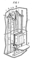
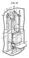
- Figure 1 is a perspective view showing the whole elevator control device.
- numeral 1 denotes a hoistway
- 2 denotes a car
- 3 denotes a car platform
- 4 denotes a bottom beam to support the car platform 3 from below
- 5 denotes side jambs provided vertically on both the right and left sides of the car
- 6 denotes a top jamb provided laterally on top of the car 2.
- Numeral 7 denotes a pair of guide rails fixed vertically on the side walls of the hoistway on both sides of the car
- 8 denotes guide rails for the counter weights which are fixed vertically on the wall behind the rear wall of the car 2, and two pairs of guide rails are provided in parallel on both the right and left sides.
- Numeral 9 denotes a pair of hoisting machines that are provided on the right and left apart from one another in a top part of the hoistway, and comprises sheaves 10, brakes 11 to stop the sheaves 10, and electric motors 12 to drive the sheaves 10.
- Numeral 13 denotes a right-and-left pair of main ropes of which one end is passed around the sheaves 10 and engaged to the bottom beam 4 of the car 2
- 14 denotes deflector sheaves that guide the main ropes 13 to the car 2
- 15 denotes shackle rods that are fixed to an end of each of the main ropes
- 16 denotes shackle springs that lie between the bottom beam 4 and each of the shackle rods
- 17 denotes counter weights that are engaged to the other end of the main ropes 13 and are provided separately on both the right and left sides.
- Numeral 18 denotes a floor on which the car 2 lands
- 19 denotes a control panel which controls each of the hoisting machines 9.
- Numeral 35 denotes a right-and-left pair of grid plates that are fixed to the guide rails 7 with the longitudinal direction arranged vertically and have slits, as shown in Figure 5 .
- Numeral 41 denotes U-shaped photosensors which are attached to the bottom beam 4 of the car 2 with the opening facing the side walls of the hoistway, and which output pulse signals of the intermittent light transmitted through the grid plates 35 which are loosely inserted into the above-mentioned opening.
- the grid plates 35 and the photosensors 41 function as car position detectors.
- the weight of the counter weights 17 is set to be balanced at a weight when 40 to 60 percent of the normal load is loaded on the car 2.
- a load according to the unbalance load 2X(Wf/4) is applied to the other brake 11, however, as the brakes 11 are set as to generate a braking torque of 250 to 300 percent of the load torque of the normal unbalance load Wf/4, it is possible to stop the car 2 of which the load is Wf with one brake.
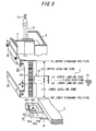
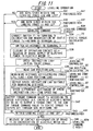
- FIG. 2 is a block diagram showing an electric circuit of an elevator control device.
- numeral 21 denotes a tension detector that is attached to the bottom surface of the bottom beam 4 of the car 2 and detects the tension of each of the main ropes 13 by detecting the expansion and contraction of the shackle springs 16, and the details thereof are shown in Figure 3 .
- Numeral 51 denotes a car operating panel, and 52 denotes a hall button provided on each floor 18.
- Numeral 53 denotes an encoder that generates pulse signals as the hoisting machines 9 rotate.
- Numeral 60 denotes an operation managing device, and comprises a call registration circuit 60a which registers calls from the car operating panel 51 and the hall buttons 52, a target travel distance calculating circuit 60b which calculates the travel distance with the distance to the destination floor as the target travel distance Do, an operation command circuit 60c which commands operation to the destination floor, a leveling command circuit 60e which commands leveling operation, and an in-car load detecting circuit 60f which calculates the load in the car 2 by summing up the tension of both of the main ropes 13 when the car 2 is at a standstill before start.
- a call registration circuit 60a which registers calls from the car operating panel 51 and the hall buttons 52
- a target travel distance calculating circuit 60b which calculates the travel distance with the distance to the destination floor as the target travel distance Do
- an operation command circuit 60c which commands operation to the destination floor
- a leveling command circuit 60e which commands leveling operation
- an in-car load detecting circuit 60f which calculates the load in the car 2 by summing up
- Numeral 61L shows equipment that is related to the travel of the car 2 in the left side, as shown by the chain line in the figure, and 61R similarly shows equipment related to the travel of the car 2 in the right side. Both equipments 61L and 61R are of the same equipment structure, thus explanation will be made without distinguishing the two.
- Numeral 62 denotes an operation contact which closes by commands from the operation command circuit 60c or the leveling command circuit 60e, and supplies electric power from the power converter 77 to the electric motor 12.
- Numeral 63 denotes a car speed calculating means to calculate the car speed Vm of the car 2 from the number of pulse signals generated per unit hour by the encoder 53.
- Numeral 64 denotes a travel distance calculator which calculates the travel distance Dm from the departure floor to the present position of the car 2 by integrating the car speed Vm.
- Numeral 65 denotes a subtracter which calculates the remaining distance Dr to the destination floor by subtracting the travel distance Dm from the target travel distance Do
- 66 denotes a position controller which outputs a speed instruction Vo suitable for the remaining distance Dr.
- the details of the speed instruction Vo is shown in Figure 8 .
- Numeral 67 denotes a switch which connects terminals a and c by commands from the operation command circuit 60c and connects terminals b and c by commands from the leveling command circuit 60e.
- Numeral 68 denotes a subtracter which calculates the speed difference between the speed instruction Vo and the car speed Vm
- 69 denotes a speed controller which outputs a torque command To suitable for the speed difference.
- Numeral 71 denotes a switch which connects terminals b and c prior to the start of the car 2 and connects terminals a and c along with the closure of the operation contact 62
- 72 denotes a static torque calculator which calculates the static torque Ts from the tension detected by the tension detector 21 of the main rope 13 at a standstill immediately before start
- 73 denotes an adder which adds the static torque Ts to the torque command To
- 74 denotes a load torque calculator which calculates the load torque Tm from the tension of the main rope 13 via the switch 71
- 75 denotes a subtracter which calculates the torque difference between the sum of the torque order To and the static torque Ts
- the load torque Tm 76 denotes a torque controller which outputs a current instruction Io suitable for the torque difference
- 77 denotes a power converter which supplies electric power to the electric motor 12 according to the current instruction Io and the output current
- 78 denotes a current transformer which detects output current from
- Numeral 79 denotes a leveling zone memory in which the leveling zones LZU and LZD that are set above and under the floor 18 are recorded. The details of the leveling zones LZU and LZD are shown in Figure 5 .
- Numeral 80 is a car position calculator which calculates the car position LDm by counting the pulse signals from the photosensor 41, and 81 denotes a subtracter which calculates the remaining distance LDr to the floor 18 by subtracting the car position LDm from the leveling zone LZU or LZD, and 82 denotes a leveling controller which outputs a speed instruction LVo suitable for the remaining distance LDr. The details of the speed instruction LVo is shown in Figure 9 .
- Numeral 85 denotes a travel distance comparator which compares the travel distance Dm of the right and left hoisting machines 9
- 86 denotes a current comparator which compares the current values of the right and left hoisting machines 9 by being inputted the current values via the current transformer 78
- 87 denotes a safety circuit which stops the right and left hoisting machines 9 when the difference in the travel distance Dm compared by the travel distance comparator 85 exceeds a predetermined value or when the difference in the current values compared by the current comparator 86 exceeds a predetermined value.
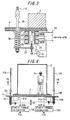
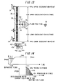
- FIG. 3 is a longitudinal section showing the main parts of the tension detector 21.
- 22 denotes a bobbin
- 23 denotes a primary winding wound around the center part of the bobbin
- 24 and 25 denote secondary windings wound around the bobbin 22 at both sides of the primary winding 23, which are connected differentially.
- Numeral 26 denotes a movable iron core loosely inserted into the bobbin 22, and is engaged to the shackle rod 15 via the bracket 27, and moves vertically in accordance with the expansion and contraction of the shackle spring 16.
- the tension detector 21 comprises a differential transformer, and the primary winding 23 is connected to the AC power source 28 of the voltage e1, and the voltages e2a and e2b are outputted to the secondary windings 24 and 25.
- the tensions of the main ropes 13 are measured in the state when there is no load in the car 2. Then, the position of the movable iron core of both the right and left tension detectors 21 is set so that the output eo becomes zero when the smaller one of the tensions acts. Accordingly, the output eo of the tension detector 21 becomes a value which is in proportion to the difference of the value where the smaller of the tensions of the right and left main ropes 13 when there is no load is the standard.
- FIG 4 shows the operation state of the above-mentioned tension detector 21. That is, the tension detectors 21 are fixed to the right and left sides of the car 2, and operate separately from each other and output the outputs eoL and eoR.
- the static torques TsL and TsR are calculated by the corresponding static torque calculators 72L and 72R according to the above-mentioned outputs eoL and eoR.
- Figure 5 is a perspective view showing the car position detector which comprises a grid plate 35 and a photosensor 41, and the grid plate 35 which has the longitudinal direction arranged vertically has slits 36 punched at a fixed pitch d, and on one side has a landing zone notch 37 which is formed from the center in the equal lengths LU, LD in the longitudinal direction.
- Numeral 38 denotes a bracket to attach the grid plate 35 to the guide rail 7.
- the photoreceivers 42r and 43r function as car position encoders which output pulse signals by the intermittence of the photorays by the grid plate 35 from the projectors 42p and 43p.
- the photoreceiver 44r detects the leveling zones LZU and LZD by the insulation of the photoray from the projector 44p by the grid plate 35, and detects the landing zones LU and LD by the passing of the photoray. Accordingly, the photoreceiver 44r functions as a landing zone detector.
- the grid plate 35 is attached to the guide rail 7 via the bracket 38 so that the center of the grid plate 35 accords with the center of the photosensor 41 which is fixed to the bottom beam 4, when the car platform 3 and the floor 18 meet.
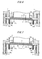
- Figure 6 shows the car 2 at a landing state. That is, the car position detectors which comprise the photosensor 41 and the grid plate 35 are fixed on the right and left sides of the car 2, and operate separately detecting the position of the car platform 3. As shown in the figure, it shall be taken that the car platform 3 is inclined from left to right at an angle of ⁇ to the floor 18, and that the right photoreceiver 44rR is within the landing zones LU and LD but the left photoreceiver 44rL is outside and above the landing zone LU. The leveling will be operated only at the left side, and landing will be operated by lowering only the left side of the car 2 so that the photoreceiver 44rL comes within the landing zones LU and LD.
- Figure 7 similarly shows the car 2 at a landing state. That is, the leveling will be operated only when both the right and left photoreceivers 44rL and 44rR are within the leveling zones LZU and LZD. As shown in the figure, when the car platform 3 stops inclined above the floor 18, and the right photoreceiver 44rR is within the leveling zone LZU but the left photoreceiver 44rL is outside and above the leveling zone LZU, leveling will not be operated.
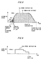
- Figure 8 shows the speed instruction Vo outputted from the position controller 66 at call response operation.
- the speed instruction Vo thereafter decelerated is outputted corresponding to the remaining distance Dr, and the elevator lands at the destination floor according to this speed instruction Vo.
- Figure 9 shows the speed instruction LVo during leveling operation.
- the speed instruction LVo in the leveling operation is outputted from the leveling controller 82, and after outputting the initial value LVmax, it outputs a speed instruction LVo which gradually decreases according to the remaining distance LDr from the subtracter 81.
- the photosensor 41 is engaged to the grid plate 35.
- the car position calculator 80 detects the travel direction of the car 2 from the order of movement of the photoreceivers 42r and 43r, and calculates the position LDm of the car 2 from the number of the pulse signals from the photoreceivers 42r or 43r.
- the position LDm of the car 2 is detected with the upper part reference position Pu as the starting point, and in ascending operation, the position LDm of the car 2 is detected with the lower part reference position Pd as the starting point.
- the leveling is operated in accordance with the speed instruction LVo.
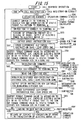
- step S13 the travel distance from the departure floor to the destination floor is calculated by the travel distance calculating circuit 60b, and is outputted as a target travel distance Do common to both the equipment 61L of the left side and the equipment 61R of the right side.
- step S14 the output from the tension detector 21 is inputted to the static torque calculator 72 by connecting the switch 71 to terminal b, and after the static torque Ts is calculated and memorized from the tension of the main rope 13 at a standstill before start, the switch 71 is connected to terminal a.
- step S15 also the switch 67 is connected to terminal a.
- step S16 the operation contact 62 is closed and the brake 11 is released, and electric power is supplied to the electric motor 12.
- step S17 the pulse signals from the encoder 53 are inputted to the car speed calculation means 63 and the car speed Vm is calculated, further, the travel distance Dm from the departure floor to the present position of the car 2 is calculated by integration of the car speed Vm by the travel distance calculator 64.
- step S18 the remaining distance Dr to the destination floor is calculated by subtraction of the travel distance Dm from the target travel distance Do by the subtracter 65.
- step S19 a speed instruction Vo suitable for the remaining distance Dr is outputted from the position controller 66.
- step S20 the speed difference ⁇ V between the speed instruction Vo and the car speed Vm is calculated by the subtracter 68.
- step S21 the torque command To is calculated by the speed controller 69 according to the speed difference ⁇ V.
- step S22 the torque command To and the static torque Ts are summed up by the adder 73.
- step S23 the torque difference ⁇ T between the sum of the torque command To and the static torque Ts, and the load torque Tm, is calculated by the subtracter 75.
- step 524 the current command Io according to the torque difference ⁇ T is calculated by the torque controller 76.
- step S25 electric power is supplied by the power converter 77 to the electric motor 12 according to the current command Io.
- step S26 when the arrival to the destination floor of the car 2 is detected by the car position detector which comprises a grid plate 35 and a photosensor 41, the procedure moves to step S27, and the operation contact 62 is opened, the brake 11 is operated, the electric motor 12 is de-energized, and the procedure returns to step S11, and operates the next call response operation. If the car 2 has not arrived to the destination floor in step S26, the procedure returns to step S17 and repeats the procedure of steps S17 through S26, and drives the car 2 to the destination floor.
- the car position detector which comprises a grid plate 35 and a photosensor 41
- step S31 it is carried on to step S32 only when both the right and left photoreceivers 44r detect the leveling zones LZU and LZD, in a case such as in Figure 6 .
- step S32 in the case where there is a photoreceiver 44r that does not detect the leveling zones LZU and LZD, leveling operation is not carried out. This is because leveling operation is inappropriate when the difference between the floor 18 and the car platform 3 is large.
- step S32 in the case where both the right and left photoreceivers 44r detect the inside of the leveling zones LU and LD, leveling operation is not carried out. This is because there is no necessity for leveling operation.
- step S33 the leveling command circuit 60e of the side which the leveling zones LU and LD are not detected operates.
- step S34 After the output from the tension detector 21 is inputted to the static torque calculator 72 by connecting the switch 71 to terminal b in step S34, and the static torque Ts is calculated and memorized from the tension of the main rope 13 at a standstill before start, the switch 71 is connected to terminal a.
- step S35 also the switch 67 is connected to terminal b.
- step S36 the brake 11 is released by closing the operation contact 62, and electric power is supplied to the electric motor 12.
- step S37 the leveling controller 82 outputs an initial value LVmax as the speed instruction LVo of the leveling operation.
- step S38 the car position LDm is read from the car position calculator 80.
- This car position LDm is calculated and memorized in advance by the car position calculator 80 from the pulse signals of the photosensor 41 which has the upper part reference position Pu or the lower part reference position Pd as the starting point when the car 2 lands on the destination floor during call response operation.
- the leveling zones LZU and LZD are read from the leveling zone memory 79, and the remaining distance LDr to the floor 18 is calculated by subtraction of the leveling zones LZU and LZD and the car position LDm by the subtracter 81.
- the leveling controller 82 outputs a speed instruction LVo which decreases gradually in accordance with the remaining distance LDr.
- the speed difference ⁇ V between the speed instruction LVo and the car speed Vm is calculated by the subtracter 68.
- Step S42 is a similar procedure as steps S21 through S25 in Figure 10 : the torque command To is calculated by the speed controller 69 according to the speed difference ⁇ V; the torque command To and the static torque Ts are summed up by the adder 73; the torque difference ⁇ V between the sum of the torque command To and the static torque Ts, and the load torque Tm, is calculated by the subtracter 75; the current command Io is calculated by the torque controller 76 in accordance with the torque difference ⁇ V; and the car 2 is driven to ascend and descend by supply of electric power to the electric motor 12 by the power converter 77 based on the current command Io.
- step S43 When entry of the car platform 3 to the landing zones LU and LD is detected by the photoreceiver 44r in step S43, the procedure moves to step S44, where the leveling operation is completed by operating the brake 11 by releasing the operation contact 62 and also de-energizing the electric motor 12. In step S43, If the car platform 3 is judged that it has not reached the landing zones LU and LD, it returns to step S38, and the procedure from step S38 through step S43 is repeated and leveling operation is carried out.
- the hoisting machines 9 drive the car 2 with suitable torques, so it is possible to prevent relative movement of the main ropes 13 and to avoid the car platform 3 from inclining extremely.
- a tension detector 21 is provided for each of the main ropes 13, and an in-car load detecting circuit 60f regarding as the in-car load the sum of the outputs of both the tension detectors at a standstill before start of the car 2 is provided, it is possible to calculate the congestion degree etc. by detecting the load in the car 2 without installation of other detectors.
- the hoisting machines can be stopped not only when the main ropes 13 actually move relatively, but also when the travel distances Dm differ from each other due to occurrence of unevenness in the rotation of the hoisting machines 9, so it is possible to detect and to cope with dispersion in the wear of the sheave 10 in the early stage.
- the load bias to the hoisting machine 9 is compared by the current comparator 86 by detecting the electric motor current via the current transformer 78, however, it is not limited only to this, and it is also acceptable to detect the load bias by comparing the load torques applied to the two hoisting machines 9.
- Figures 12 through 15 show the second embodiment of the elevator control device comprising a plurality of hoisting machines in accordance with the present invention.
- the speed instruction is calculated according to the passing of time and the hoisting machines are controlled together, and from the point of deceleration to the destination floor, the hoisting machines are controlled separately with speed instructions suitable for the remaining distance.
- Figure 12 is a block diagram showing an electric circuit of the elevator control device; numeral 91 denotes a right-and-left pair of grid plates which are fixed to the guide rails 7 with the longitudinal direction arranged vertically and which have slits 36 arranged from the upper and lower deceleration points PPu and PPd to the floor position, as shown in detail in Figure 13 .
- Numeral 100 denotes an operation managing device which comprises a call registration circuit 60a, an operation command circuit 60c, a leveling command circuit 60e, an in-car load detecting circuit 60f, and also a deceleration command circuit 60d which commands deceleration when the photosensor 41 is engaged to the grid plate 91 and detects a deceleration point set at a predetermined distance before the destination floor.
- Numeral 101 denotes a speed per time calculator which controls both of the hoisting machines 9 together by computing the speed instruction Vao in accordance with the lapse of time when an operation command is given from the operation command circuit 60c.
- numeral 102L denotes equipment related to the travel of the left main rope 13L on the left side of the car 2
- numeral 102R denotes equipment related to the travel on the right side of the car 2. Both the equipments 102L and 102R are of the same equipment structure, thus explanation will be made without distinguishing the two.
- Numeral 103 denotes a deceleration controller that generates a speed instruction Vdo as shown in Figure 14 , by calculating the speed suitable for the remaining distance GDr from the deceleration point to the destination floor for each hoisting machine 9.
- Numeral 104 denotes a switch which has the terminals a and d connected by the command from the operation command circuit 60c, the terminals b and d connected by the command of the deceleration command circuit 60d, and the terminals c and d connected by the command of the leveling command circuit 60e.
- Numeral 105 denotes a part which comprises the same elements as the elements to which are given the numerals 71 through 77 in Figure 2 .
- Numeral 106 denotes a car position calculator which calculates the car position GDm by counting the pulse signals from the photosensor 41, and 107 denotes a deceleration distance memory in which is recorded the deceleration distance GZU and GZD from the deceleration point to the floor 18 recorded.
- Numeral 108 denotes a subtracter which calculates the remaining distance GDr by subtracting the car position GDm, which has the deceleration point as the starting point, from the deceleration distance GZU or GZD.
- Figure 13 is a perspective view showing the car position detector which comprises a grid plate 91 and a photosensor 41 , and in the grid plate 91 which has the longitudinal direction arranged vertically, there are slits 36 punched at a fixed pitch d from the upper and lower deceleration points PPu and PPd to the floor 18, and also on one side, there is a landing zone notch 37 formed at the equal lengths LU, LD in the longitudinal direction, the floor 18 being the center, and also a shielding part 92 to specify the leveling zones LZU and LZD, the floor 18 being the center, is formed above and below the landing zone notch 37.
- the grid plate 91 specifies the deceleration distances GZU and GZD to the floor 18 with the upper deceleration point PPu or the lower deceleration point PPd being the starting point, specifies the leveling zones LZU and LZD which have the upper reference position Pu or the lower reference position Pd as the starting point, and also specifies the landing zones LU and LD.
- Figure 14 shows the speed instruction Vao outputted from the speed per time calculator 101, and the speed instruction Vdo outputted from the deceleration controller 103.
- the speed instruction Vao increases the speed progressively as the predetermined time ⁇ t passes, and when it reaches the rated speed Vmax, it becomes a stable value.
- the car position calculator 106 calculates the car position GDm, with the upper deceleration point PPu as the starting point during descending operation, and with the lower deceleration point PPd as the starting point during ascending operation.
- the deceleration controller 103 calculates a speed suitable for the remaining distance GDr. This speed is outputted as a speed instruction Vdo via the switch 104.
- step S51 When a hall call or a car call is registered with the call registration circuit 60a, the procedure is moved from step S51 to step S52, and an operation command is given from the operation command circuit 60c to respond to the call.
- the switch 71 After calculating and memorizing the static torque Ts from the tension of the main rope 13 at a standstill before start by connecting the switch 71 to terminal b in step S53, the switch 71 is connected to terminal a.
- step S54 the switch 104 is connected to terminal a.
- step S55 the operation contact 62 is closed and the brake 11 is released, and electric power is supplied to the electric motor 12.
- step S56 a speed instruction Vao is outputted from the speed per time calculator 101 by the operation command from the operation command circuit 60c.
- step S57 the speed difference ⁇ V between the speed instruction Vao and the car speed Vm is calculated by the subtracter 68.
- Step S58 is a similar procedure as that shown in Steps S21 through S25 in Figure 10 , and calculates a torque command To according to the speed difference ⁇ V, and energizes the electric motor 12 so as to output a torque which is an addition of the static torque Ts to the torque command To, to make the car 2 ascend and descend.
- step S59 whether or not a deceleration command is outputted from the deceleration command circuit 60d is checked by engaging the photosensor 41 to the grid plate 91. In the case where a speed instruction is not yet outputted, the procedure returns to step S56, and steps 56 through 59 are repeated.
- step S59 the terminals b and d of the switch 104 are connected in step S60.
- step S61 the car position GDm, which has the deceleration point PPu or PPd as the starting point, is read from the car position calculator 106.
- step S62 the deceleration distance GZU or GZD is read from the deceleration distance memory 107, and the remaining distance GDr to the floor 18 is read by subtraction of the car position GDm from the deceleration distance GZU or GZD by the subtracter 108.
- step S63 as shown in Figure 14 , the deceleration controller 103 outputs a speed instruction Vdo which progressively decreases according to the remaining distance GDr.
- step S64 the speed difference ⁇ V between the speed instruction Vdo and the car speed Vm is calculated by the subtracter 68.
- Step S65 is a similar procedure as that shown in steps S1 through S25 in Figure 10 , and calculates the torque command To according to the speed difference ⁇ V, and performs deceleration operation by energizing the electric motor 12 by outputting a torque which is the sum of the static torque Ts added to the torque command To.
- step S66 when the photosensor 44r detects entry of the car platform 3 into the landing zones LU and LD, the procedure moves on to step S67, and call response operation is finished by operating the brake 11 by releasing the operation contact 62 along with de-energizing the electric motor 12.
- step S66 if the car platform 3 is judged that it has not reached the landing zones LU and LD, the procedure returns to step S61, and call response operation is performed by repeating the procedure from step S61 through step S66.
- the leveling operation is the same as that shown in Figure 11 , thus explanation is omitted.
- the speed instruction Vao is outputted according to the lapse of time from the speed per time calculator 101, therefore, calculation of the speed instruction Vao is easy.
- both the right and left hoisting machines 9L and 9R are controlled together by the same speed instruction Vao, so it is unlikely that the difference in the travel distance between the two would occur.
- Figure 16 shows a third embodiment in accordance with the present invention.
- the counter weights 17 are separately suspended at the right and left sides, however, in this third embodiment, a common counter weight is suspended by a left main rope 13L and a right main rope 13R. That is, the two ends of the main ropes 13L and 13R are engaged to a common car 2 and a common counter weight 17A.
- the weight of the counter weight 17A is set in the similar way as in the first embodiment, therefore, even in the case where one of the brakes does not function, it is possible to stop the car 2 of the load of Wf with only the other brake 11.
- the counter weight is common to both of the main ropes 13L and 13R, only one pair of counter weight guide rails 8 is necessary, thus making the installation work reduced.
- the elevator control device in accordance with the present invention which comprises a plurality of hoisting machines, is suitable for a control device for elevators which need to have a plurality of hoisting machines installed in a small space. Moreover, it is suitable for a control device for elevators which have a limit to lifting of heavy loads at the time of installation.
Landscapes
- Engineering & Computer Science (AREA)
- Automation & Control Theory (AREA)
- Computer Networks & Wireless Communication (AREA)
- Elevator Control (AREA)
- Lift-Guide Devices, And Elevator Ropes And Cables (AREA)
Claims (8)
- Dispositif de commande d'ascenseur pour l'entraînement d'une cabine (2) pour monter et descendre avec des câbles métalliques principaux (13) qui sont remontés en étant engagés séparément sur une pluralité de positions de ladite cabine (2) et qui sont passés autour d'une pluralité de machines de levage individuelles (9L, 9R) installées en correspondant auxdits câbles métalliques principaux (13),
caractérisé en ce que des tensions de chaque câble métallique principal ou de chaque ensemble desdits câbles métalliques principaux (13) au moment d'un arrêt de la cabine (2) sont détectées séparément par des détecteurs de tension (21), et ladite cabine (2) est entraînée pour monter et descendre en augmentant et en diminuant les puissances provenant desdites machines de levage correspondantes (9L, 9R), selon les valeurs détectées. - Dispositif de commande d'ascenseur selon la revendication 1, caractérisé par le fait de comprendre des moyens de détection de charge à l'intérieur de la cabine, pour détecter la charge à l'intérieur de la cabine en totalisant, avec les détecteurs de tension (21), la tension de chaque câble métallique principal lors d'un arrêt.
- Dispositif de commande d'ascenseur pour entraîner une cabine (2) pour monter et descendre avec des câbles métalliques principaux (13) qui sont remontés en étant engagés séparément sur une pluralité de positions de ladite cabine (2) et qui sont passés autour d'une pluralité de machines de levage (9L, 9R) installées en correspondant auxdits câbles métalliques principaux (13), caractérisé en ce qu'une différence de niveau existant entre l'étage (18) et la plateforme de la cabine, au moment de l'arrivée de ladite cabine (2) à l'étage de destination, est détectée au niveau de chaque position d'engagement desdits câbles métalliques principaux (13), et au cas où la valeur détectée dépasse une valeur prédéterminée, la mise à niveau est opérée avec un mouvement vertical séparé desdites positions d'engagement des câbles métalliques principaux (13) et réalisée par lesdites machines de levage correspondantes (9L, 9R) pour diminuer ladite différence.
- Dispositif de commande d'un ascenseur dans lequel une cabine (2) est entraînée pour monter et descendre avec des câbles métalliques principaux (13) qui sont remontés en étant engagés séparément sur une pluralité de positions de ladite cabine (2) et qui sont passés autour d'une pluralité de machines de levage (9L, 9R) installées en correspondant auxdits câbles métalliques principaux (13),
caractérisé en ce que chaque machine de levage comprend un calculateur de distance de course (64) pour calculer une distance de course (Dm), et un circuit de sécurité (87) pour stopper lesdites machines de levage (9L, 9R), au cas où la différence de ladite valeur calculée dépasse une valeur prédéterminée. - Dispositif de commande d'un ascenseur selon la revendication 4, caractérisé en ce que le calculateur de distance de course (64) est un instrument de mesure d'angle de rotation, pour mesurer un angle de rotation des machines de levage (9L, 9R).
- Dispositif de commande d'un ascenseur selon la revendication 1, caractérisé en ce que les puissances des moteurs électriques pour entraîner lesdites machines de levage (9L, 9R) sont mesurées séparément pour chaque machine de levage, et par le fait de comporter un circuit de sécurité (87) pour stopper lesdites machines de levage (9L, 9R) au cas où une différence des valeurs mesurées dépasse une valeur prédéterminée.
- Dispositif de commande d'un ascenseur pour entraîner une cabine (2) pour monter et descendre avec des câbles métalliques principaux (13) qui sont remontés en étant engagés séparément sur une pluralité de positions de ladite cabine (2) et qui sont passés autour d'une pluralité de machines de levage (9L, 9R) installées en correspondant auxdits câbles métalliques principaux (13), caractérisé par le fait de comprendre :des moyens de calcul de la distance de course cible pour précalculer et donner auxdites machines de levage (9L, 9R), comme distance de course cible commune (Do), la distance de course (Dm) depuis l'étage de départ jusqu'à l'étage de destination ;des moyens de mesure de la distance de course pour mesurer la distance de course (Dm) depuis ledit étage de départ jusqu'à la présente position de ladite cabine (2) au niveau de chacune desdites positions d'engagement ;des moyens de calcul de la distance restante pour calculer la distance restante (Dr) jusqu'audit étage de destination au niveau de chacune desdites positions d'engagement des câbles métalliques principaux (13), en soustrayant ladite valeur mesurée, de ladite distance de course cible (Do) ; etdes moyens de commande de la position de course pour fournir, comme instructions de vitesse (Vo), une vitesse appropriée pour ladite distance restante (Dr), pour chacune desdites machines de levage correspondantes (9L, 9R) ;dans lequel lesdites machines de levage correspondantes (9L, 9R) sont commandées séparément par lesdites instructions de vitesse (Vo).
- Dispositif de commande d'un ascenseur pour l'entraînement d'une cabine (2) pour monter et descendre avec des câbles métalliques principaux (13) qui sont remontés en étant engagés séparément sur une pluralité de positions de ladite cabine (2) et qui sont passés autour d'une pluralité de machines de levage (9L, 9R) installées en correspondant auxdits câbles métalliques principaux (13), caractérisé par le fait de comprendre :des moyens de calcul d'une estimation de temps pour calculer une instruction de vitesse (Vo) selon un laps de temps écoulé ;des moyens de détection d'un point de décélération pour détecter, au niveau de chacune desdites positions d'engagement, des points de décélération fixés à une distance prédéterminée avant l'étage de destination ; etdes moyens de calcul de la distance et de la vitesse pour fournir une vitesse appropriée pour la distance restante (Dr) depuis la présente position de ladite cabine (2) jusqu'à l'étage de destination, servant d'instruction de vitesse (Vo) au niveau de chacune desdites positions d'engagement des câbles métalliques principaux (13) ;dans lequel lesdites machines de levage (9L, 9R) sont commandées ensemble par une instruction de vitesse (Vo) calculée par lesdits moyens de calcul de la distance et de la vitesse lorsque l'instruction de vitesse (Vo) est donnée auxdites machines de levage (9L, 9R), et lesdits moyens de calcul de l'estimation de temps passent en mode de calcul de la distance et de la vitesse dans chacune desdites machines de levage correspondantes (9L, 9R), et lesdites machines de levage correspondantes (9L, 9R) sont commandées séparément par l'instruction de vitesse (Vo) calculée par lesdits moyens de calcul de la distance et de la vitesse, depuis lesdits points de décélération jusqu'audit étage de destination, lorsque lesdits moyens de calcul des points de décélération détectent ledit point de décélération.
Applications Claiming Priority (1)
| Application Number | Priority Date | Filing Date | Title |
|---|---|---|---|
| PCT/JP2002/009267 WO2004024609A1 (fr) | 2002-09-11 | 2002-09-11 | Organe de commande d'ascenseur |
Publications (3)
| Publication Number | Publication Date |
|---|---|
| EP1538121A1 EP1538121A1 (fr) | 2005-06-08 |
| EP1538121A4 EP1538121A4 (fr) | 2011-03-30 |
| EP1538121B1 true EP1538121B1 (fr) | 2012-12-05 |
Family
ID=31986081
Family Applications (1)
| Application Number | Title | Priority Date | Filing Date |
|---|---|---|---|
| EP02765482A Expired - Lifetime EP1538121B1 (fr) | 2002-09-11 | 2002-09-11 | Organe de commande d'ascenseur |
Country Status (5)
| Country | Link |
|---|---|
| EP (1) | EP1538121B1 (fr) |
| JP (1) | JP4288236B2 (fr) |
| KR (1) | KR100619616B1 (fr) |
| CN (1) | CN100372752C (fr) |
| WO (1) | WO2004024609A1 (fr) |
Families Citing this family (14)
| Publication number | Priority date | Publication date | Assignee | Title |
|---|---|---|---|---|
| FI119766B (fi) | 2004-04-08 | 2009-03-13 | Kone Corp | Menetelmä hissin taitto- ja/tai vetopyörien köysiurien kulumisen tunnistamiseksi ja hissi |
| JP4850708B2 (ja) * | 2004-07-12 | 2012-01-11 | 三菱電機株式会社 | エレベータの制御システム |
| CN101107188A (zh) * | 2005-03-01 | 2008-01-16 | 三菱电机株式会社 | 电梯装置 |
| EP1918239B1 (fr) * | 2005-08-25 | 2016-09-21 | Mitsubishi Denki Kabushiki Kaisha | Dispositif d'ascenseur |
| JP4896973B2 (ja) * | 2006-05-29 | 2012-03-14 | 三菱電機株式会社 | エレベータのドア装置 |
| EP2130792A4 (fr) | 2007-03-23 | 2013-10-23 | Mitsubishi Electric Corp | Système de commande d'ascenseur |
| FR2917375B1 (fr) | 2007-06-15 | 2009-11-13 | Airbus France | Aeronef comportant une plateforme mobile entre deux niveaux de l'aeronef |
| US8162110B2 (en) | 2008-06-19 | 2012-04-24 | Thyssenkrupp Elevator Capital Corporation | Rope tension equalizer and load monitor |
| JP5570602B2 (ja) * | 2010-08-20 | 2014-08-13 | 三菱電機株式会社 | エレベータ装置 |
| JP2013001474A (ja) * | 2011-06-14 | 2013-01-07 | Hitachi Ltd | エレベーターの安全運転システムおよび安全運転方法 |
| FI125200B (fi) * | 2013-07-04 | 2015-06-30 | Kone Oyj | Järjestely kuormituksen muutoksen aiheuttaman hissikorin siirtymän pienentämiseksi |
| KR20180086785A (ko) | 2017-01-23 | 2018-08-01 | 주식회사 바이오넷 | 산모 및 태아 감시 장치 및 방법 |
| EP3456674B1 (fr) | 2017-09-15 | 2020-04-01 | Otis Elevator Company | Système de detection de mou d'un element de tension d'ascenseur et procede pour effectuer une operation d'arret d'urgence d'un ascenseur |
| EP3845480A1 (fr) * | 2019-12-31 | 2021-07-07 | Inventio AG | Procédé de déplacement d'une cabine d'un ascenseur pour évacuer des passagers et dispositif d'ouverture de frein pour déplacer une cabine d'ascenseur |
Family Cites Families (18)
| Publication number | Priority date | Publication date | Assignee | Title |
|---|---|---|---|---|
| CA1036080A (fr) * | 1976-02-13 | 1978-08-08 | Canadian General Electric Company Limited | Treuil repartiteur des charges |
| JPS60213676A (ja) * | 1984-04-05 | 1985-10-25 | 東芝昇降機サ−ビス株式会社 | エレベ−タ−の作業台平衡装置 |
| JPH0725499B2 (ja) * | 1986-10-20 | 1995-03-22 | 株式会社日立製作所 | エレベーター装置およびエレベーターの起動補償方法 |
| JPH0570055A (ja) * | 1991-09-13 | 1993-03-23 | Mitsubishi Electric Corp | エレベーターの据付用昇降台 |
| JPH0570057A (ja) * | 1991-09-17 | 1993-03-23 | Hitachi Building Syst Eng & Service Co Ltd | エレベータ装置 |
| JP2576808Y2 (ja) * | 1992-03-23 | 1998-07-16 | 新明和工業株式会社 | 立体駐車装置 |
| JP2707942B2 (ja) * | 1993-02-10 | 1998-02-04 | 三菱電機株式会社 | エレベータのロープ張力平衡装置 |
| JPH0725553A (ja) * | 1993-07-09 | 1995-01-27 | Mitsubishi Electric Corp | エレベータの制御システム |
| JP2887861B2 (ja) * | 1994-07-13 | 1999-05-10 | 株式会社日立製作所 | エレベーターの制御装置 |
| JPH08217378A (ja) * | 1995-02-08 | 1996-08-27 | Mitsubishi Electric Corp | クレーンの制御装置 |
| JP3174475B2 (ja) * | 1995-03-30 | 2001-06-11 | 三菱電機株式会社 | 昇降搬送装置の制御装置 |
| JPH08301539A (ja) * | 1995-05-01 | 1996-11-19 | Hitachi Ltd | エレベーターの制御装置及び制御方法 |
| JP3477377B2 (ja) * | 1998-09-17 | 2003-12-10 | 東海旅客鉄道株式会社 | クレーンの共吊り運転制御方法 |
| JP2000272849A (ja) * | 1999-03-26 | 2000-10-03 | Mitsui Miike Mach Co Ltd | 運搬用昇降機の運転制御方法 |
| JP2001233553A (ja) * | 2000-02-24 | 2001-08-28 | Toshiba Corp | ダブルデッキエレベータの制御装置 |
| JP2001261257A (ja) * | 2000-03-23 | 2001-09-26 | Mitsubishi Electric Corp | エレベータ装置 |
| JP3376477B2 (ja) * | 2000-08-01 | 2003-02-10 | 伊東電機株式会社 | 昇降装置における複数のブラシレスモータの同期方法 |
| JPWO2003078290A1 (ja) * | 2002-03-15 | 2005-07-14 | 三菱電機株式会社 | エレベータ用巻上機およびエレベータ装置 |
-
2002
- 2002-09-11 JP JP2004535830A patent/JP4288236B2/ja not_active Expired - Fee Related
- 2002-09-11 EP EP02765482A patent/EP1538121B1/fr not_active Expired - Lifetime
- 2002-09-11 WO PCT/JP2002/009267 patent/WO2004024609A1/fr not_active Ceased
- 2002-09-11 CN CNB028227816A patent/CN100372752C/zh not_active Expired - Fee Related
- 2002-09-11 KR KR1020047007099A patent/KR100619616B1/ko not_active Expired - Fee Related
Also Published As
| Publication number | Publication date |
|---|---|
| KR100619616B1 (ko) | 2006-09-01 |
| EP1538121A1 (fr) | 2005-06-08 |
| KR20040083056A (ko) | 2004-09-30 |
| JPWO2004024609A1 (ja) | 2006-01-05 |
| JP4288236B2 (ja) | 2009-07-01 |
| CN1589225A (zh) | 2005-03-02 |
| CN100372752C (zh) | 2008-03-05 |
| WO2004024609A1 (fr) | 2004-03-25 |
| EP1538121A4 (fr) | 2011-03-30 |
Similar Documents
| Publication | Publication Date | Title |
|---|---|---|
| EP1538121B1 (fr) | Organe de commande d'ascenseur | |
| KR100775947B1 (ko) | 엘레베이터 | |
| EP2454182B1 (fr) | Economies d énergie grâce à des profils de déplacement optimisés | |
| JP5307394B2 (ja) | エレベータの制御装置 | |
| KR101245570B1 (ko) | 엘리베이터를 설치하는 방법 및 엘리베이터 | |
| JP2608951B2 (ja) | リニアモータ駆動型エレベータにおけるロープ重量補正装置 | |
| US20210371241A1 (en) | Elevator safety monitoring system, elevator system, elevator drive unit, and method for operating an elevator | |
| JP2001002346A (ja) | ロープ式エレベータ及びロープ式エレベータシステム | |
| KR100415749B1 (ko) | 엘리베이터 장치 | |
| EP1512652B1 (fr) | Ascenseur | |
| JP2002145544A (ja) | エレベータ駆動制御装置 | |
| CN101037164B (zh) | 电梯控制装置 | |
| JPH0725553A (ja) | エレベータの制御システム | |
| KR100597941B1 (ko) | 엘리베이터용 권양기 및 엘리베이터 장치 | |
| JP2005132541A (ja) | 昇降機械駆動用電動機の制御方法 | |
| US7299896B1 (en) | Elevator system having drive motor located adjacent to hoistway door | |
| KR100735352B1 (ko) | 엘리베이터의 제어장치 | |
| CN121443545A (zh) | 包括多个驱动机器的重负载电梯系统 | |
| KR100871514B1 (ko) | 엘리베이터의 제어 시스템 | |
| KR20070024560A (ko) | 엘리베이터의 제어 시스템 | |
| KR200288350Y1 (ko) | 엘리베이터 | |
| JP2616575B2 (ja) | エレベーター装置 | |
| KR100206988B1 (ko) | 엘리베이터의 자동 발란스 조정방법 | |
| JPH04297673A (ja) | 立体駐車設備の速度制御装置 | |
| JPH04164793A (ja) | ロープレスリニアモータエレベーター |
Legal Events
| Date | Code | Title | Description |
|---|---|---|---|
| PUAI | Public reference made under article 153(3) epc to a published international application that has entered the european phase |
Free format text: ORIGINAL CODE: 0009012 |
|
| 17P | Request for examination filed |
Effective date: 20040325 |
|
| AK | Designated contracting states |
Kind code of ref document: A1 Designated state(s): AT BE BG CH CY CZ DE DK EE ES FI FR GB GR IE IT LI LU MC NL PT SE SK TR |
|
| RBV | Designated contracting states (corrected) |
Designated state(s): AT BE DE NL |
|
| RAP1 | Party data changed (applicant data changed or rights of an application transferred) |
Owner name: MITSUBISHI DENKI KABUSHIKI KAISHA |
|
| A4 | Supplementary search report drawn up and despatched |
Effective date: 20110225 |
|
| RBV | Designated contracting states (corrected) |
Designated state(s): DE NL |
|
| 17Q | First examination report despatched |
Effective date: 20110609 |
|
| RIC1 | Information provided on ipc code assigned before grant |
Ipc: B66B 1/28 20060101ALI20120420BHEP Ipc: B66B 1/44 20060101AFI20120420BHEP |
|
| GRAP | Despatch of communication of intention to grant a patent |
Free format text: ORIGINAL CODE: EPIDOSNIGR1 |
|
| GRAS | Grant fee paid |
Free format text: ORIGINAL CODE: EPIDOSNIGR3 |
|
| GRAA | (expected) grant |
Free format text: ORIGINAL CODE: 0009210 |
|
| AK | Designated contracting states |
Kind code of ref document: B1 Designated state(s): DE |
|
| RBV | Designated contracting states (corrected) |
Designated state(s): DE |
|
| REG | Reference to a national code |
Ref country code: DE Ref legal event code: R096 Ref document number: 60244173 Country of ref document: DE Effective date: 20130131 |
|
| PLBE | No opposition filed within time limit |
Free format text: ORIGINAL CODE: 0009261 |
|
| STAA | Information on the status of an ep patent application or granted ep patent |
Free format text: STATUS: NO OPPOSITION FILED WITHIN TIME LIMIT |
|
| 26N | No opposition filed |
Effective date: 20130906 |
|
| REG | Reference to a national code |
Ref country code: DE Ref legal event code: R097 Ref document number: 60244173 Country of ref document: DE Effective date: 20130906 |
|
| REG | Reference to a national code |
Ref country code: DE Ref legal event code: R084 Ref document number: 60244173 Country of ref document: DE |
|
| REG | Reference to a national code |
Ref country code: DE Ref legal event code: R084 Ref document number: 60244173 Country of ref document: DE Effective date: 20141107 |
|
| PGFP | Annual fee paid to national office [announced via postgrant information from national office to epo] |
Ref country code: DE Payment date: 20180828 Year of fee payment: 17 |
|
| REG | Reference to a national code |
Ref country code: DE Ref legal event code: R119 Ref document number: 60244173 Country of ref document: DE |
|
| PG25 | Lapsed in a contracting state [announced via postgrant information from national office to epo] |
Ref country code: DE Free format text: LAPSE BECAUSE OF NON-PAYMENT OF DUE FEES Effective date: 20200401 |