EP1538017B1 - Transmission pour un véhicule à quatre roues motrices - Google Patents
Transmission pour un véhicule à quatre roues motrices Download PDFInfo
- Publication number
- EP1538017B1 EP1538017B1 EP04028469A EP04028469A EP1538017B1 EP 1538017 B1 EP1538017 B1 EP 1538017B1 EP 04028469 A EP04028469 A EP 04028469A EP 04028469 A EP04028469 A EP 04028469A EP 1538017 B1 EP1538017 B1 EP 1538017B1
- Authority
- EP
- European Patent Office
- Prior art keywords
- power transmission
- power
- vehicle
- turning
- gear unit
- Prior art date
- Legal status (The legal status is an assumption and is not a legal conclusion. Google has not performed a legal analysis and makes no representation as to the accuracy of the status listed.)
- Expired - Lifetime
Links
Images


Classifications
-
- B—PERFORMING OPERATIONS; TRANSPORTING
- B60—VEHICLES IN GENERAL
- B60K—ARRANGEMENT OR MOUNTING OF PROPULSION UNITS OR OF TRANSMISSIONS IN VEHICLES; ARRANGEMENT OR MOUNTING OF PLURAL DIVERSE PRIME-MOVERS IN VEHICLES; AUXILIARY DRIVES FOR VEHICLES; INSTRUMENTATION OR DASHBOARDS FOR VEHICLES; ARRANGEMENTS IN CONNECTION WITH COOLING, AIR INTAKE, GAS EXHAUST OR FUEL SUPPLY OF PROPULSION UNITS IN VEHICLES
- B60K17/00—Arrangement or mounting of transmissions in vehicles
- B60K17/34—Arrangement or mounting of transmissions in vehicles for driving both front and rear wheels, e.g. four wheel drive vehicles
- B60K17/348—Arrangement or mounting of transmissions in vehicles for driving both front and rear wheels, e.g. four wheel drive vehicles having differential means for driving one set of wheels, e.g. the front, at one speed and the other set, e.g. the rear, at a different speed
-
- B—PERFORMING OPERATIONS; TRANSPORTING
- B60—VEHICLES IN GENERAL
- B60K—ARRANGEMENT OR MOUNTING OF PROPULSION UNITS OR OF TRANSMISSIONS IN VEHICLES; ARRANGEMENT OR MOUNTING OF PLURAL DIVERSE PRIME-MOVERS IN VEHICLES; AUXILIARY DRIVES FOR VEHICLES; INSTRUMENTATION OR DASHBOARDS FOR VEHICLES; ARRANGEMENTS IN CONNECTION WITH COOLING, AIR INTAKE, GAS EXHAUST OR FUEL SUPPLY OF PROPULSION UNITS IN VEHICLES
- B60K23/00—Arrangement or mounting of control devices for vehicle transmissions, or parts thereof, not otherwise provided for
- B60K23/04—Arrangement or mounting of control devices for vehicle transmissions, or parts thereof, not otherwise provided for for differential gearing
-
- B—PERFORMING OPERATIONS; TRANSPORTING
- B60—VEHICLES IN GENERAL
- B60K—ARRANGEMENT OR MOUNTING OF PROPULSION UNITS OR OF TRANSMISSIONS IN VEHICLES; ARRANGEMENT OR MOUNTING OF PLURAL DIVERSE PRIME-MOVERS IN VEHICLES; AUXILIARY DRIVES FOR VEHICLES; INSTRUMENTATION OR DASHBOARDS FOR VEHICLES; ARRANGEMENTS IN CONNECTION WITH COOLING, AIR INTAKE, GAS EXHAUST OR FUEL SUPPLY OF PROPULSION UNITS IN VEHICLES
- B60K23/00—Arrangement or mounting of control devices for vehicle transmissions, or parts thereof, not otherwise provided for
- B60K23/08—Arrangement or mounting of control devices for vehicle transmissions, or parts thereof, not otherwise provided for for changing number of driven wheels, for switching from driving one axle to driving two or more axles
- B60K23/0808—Arrangement or mounting of control devices for vehicle transmissions, or parts thereof, not otherwise provided for for changing number of driven wheels, for switching from driving one axle to driving two or more axles for varying torque distribution between driven axles, e.g. by transfer clutch
Definitions
- This invention relates to a power transmission system for four-wheel drive vehicle, specifically to a power transmission system which adjusts the distribution of power to the front and rear wheels of a vehicle according to a driving state of the vehicle.
- EP 0844129 A discloses a power transmission system according to the preamble of claim 1.
- the four-wheel drive vehicle disclosed in this patent publication is based on a front-engine/front-drive vehicle, and arranged to supply power from an engine to the front wheels via an automatic transmission and supply part of the power from the engine to the rear wheels via a transfer clutch.
- the amount of power transmitted to the rear wheels is adjusted by controlling the engaging force of the transfer clutch.
- the distribution of power between the front wheels and the rear wheels is changed to achieve behaviors of the vehicle suitable for its driving state, such as ease of turning at an early stage of steering, restriction of slip in rapid acceleration, and stability in deceleration.
- An object of the invention is to provide a power transmission system for four-wheel drive vehicle which can control the turning characteristics of the vehicle appropriately, avoiding increase in vehicle weight and significant increase in production cost.
- the present invention provides a power transmission system for four-wheel drive vehicle, comprising a power transmission mechanism (8) provided in a vehicle arranged such that power is always transmitted to a first pair of wheels which is one of two pairs consisting of a pair of front wheels (5a) and a pair of rear wheels (5b), to transmit power to a second pair of wheels which is the other of the two pairs; a power transmission control means (11) for controlling the power transmission mechanism (8) to adjust the power (Tout) transmitted to the second pair of wheels; and a differential gear unit (9) arranged between the left and right wheels in the second pair, to distribute the power (Tout) transmitted from the power transmission mechanism (8) to the second pair, between the left and right wheels in the second pair, characterized in that the differential gear unit (9) is a torque-sensitive differential gear unit with a differential limiting function for producing a differential limiting force between the left and right wheels in the second pair, depending on the power transmitted thereto, and the power transmission control means (11) controls the power (Tout) transmitted from
- power is always transmitted to the first pair of wheels, which is one of the two pairs consisting of a pair of front wheels and a pair of rear wheels, while power determined by the control performed by the power transmission control means is transmitted to the second pair of wheels via the power transmission mechanism and distributed between the left and right wheels in the second pair by the differential gear unit.
- the power transmission control means controls power according to a driving state of the vehicle. When the power supplied to the torque-sensitive differential gear unit with a differential limiting function is changed by this control, a differential limiting force is produced between the left and right wheels in the second pair, depending on this change in the power supplied.
- the distribution of power between the inner wheel located inside in turning and the outer wheel located outside in turning changes depending on the differential limiting force produced between the inner and outer wheels, and consequently a yawing moment having such direction that hinders the turning of the vehicle or a yawing moment having such direction that promotes the turning of the vehicle acts on the vehicle.
- the turning characteristics of the vehicle can be controlled appropriately, depending on the power transmitted to the differential gear unit.
- devices such as a braking force control device and a traction control device which are provided for controlling the turning characteristics of the vehicle are not required any longer, so that the turning characteristics of the vehicle can be controlled appropriately, without increase in vehicle weight and significant increase in production cost caused by providing such devices.
- the power transmission control means includes a turning state detecting means for detecting a turning state of the vehicle and controls the power transmission mechanism according to the turning state detected by the turning state detecting means.
- the power transmission mechanism is controlled by the power transmission control means according to the turning state of the vehicle, for example, whether the vehicle is now in understeer state or in oversteer state, a yawing moment having a direction appropriate to the current turning state of the vehicle can be produced.
- the power transmission control means should be arranged to decrease the power transmitted to the differential gear unit to produce a yawing moment having such direction that promotes turning of the vehicle, and increase the power transmitted to the differential gear unit to produce a yawing moment having such direction that hinders turning of the vehicle.
- the differential limiting force is controlled as follows: In order to produce a yawing moment having such direction that promotes the turning of the vehicle, the power transmitted to the differential gear unit is decreased to decrease the differential limiting force; and in order to produce a yawing moment having such direction that hinders the turning of the vehicle, the power transmitted to the differential gear unit is increased to increase the differential limiting force.
- the power transmission control means should be arranged to increase the power transmitted to the differential gear unit to produce a yawing moment having such direction that promotes turning of the vehicle, and decrease the power transmitted to the differential gear unit to produce a yawing moment having such direction that hinders turning of the vehicle.
- the revolving speed of the inner wheel located inside in turning in the second pair is normally lower than the revolving speed of the outer wheel located outside in turning in the second pair.
- the power transmitted to the differential gear unit is increased to produce a differential limiting force
- power is transmitted from the outer wheel revolving at higher speed to the inner wheel revolving at lower speed, so that the driving force exerted via the inner wheel becomes greater than the driving force exerted via the outer wheel.
- the power transmitted to the differential gear unit is further increased to increase the differential limiting force, the driving force exerted via the inner wheel increases, and the inner wheel slips. Consequently the revolving speed of the inner wheel becomes higher than that of the outer wheel.
- the power transmitted to the differential gear unit is decreased to decrease the differential limiting force to increase the driving force exerted via the inner wheel.
- the power transmission control means sets the power transmitted to the differential gear unit to be a predetermined value or greater to produce a yawing moment having such direction that promotes turning of the vehicle, and sets the power transmitted to the differential gear unit to be less than the predetermined value to produce a yawing moment having such direction that hinders turning of the vehicle.
- a yawing moment having such direction that promotes turning of the vehicle can be produced by setting the power transmitted to the differential gear unit to be a predetermined value or greater.
- the driving force exerted via the inner wheel located inside in turning in the second pair is increased to make this wheel slip and thereby increase the revolving speed thereof, the driving force exerted via the outer wheel located outside in turning in the second pair is increased.
- a yawing moment having such direction that hinders turning of the vehicle can be produced by setting the power transmitted to the differential gear unit to be less than the predetermined value. In this case, by limiting the differential motion without causing the inner wheel to slip, the driving force exerted via the inner wheel is increased.
- the power transmission control means controls the power transmission mechanism according to a target power transmission amount that is set based on at least either a driving state or a running state of the vehicle.
- the power transmission mechanism can be controlled in the manner reflecting the driving state or the running state of the vehicle.
- the turning characteristics of the vehicle can be controlled more appropriately.
- the power transmission control means sets the target power transmission amount based on an actual yaw rate of the vehicle and a target yaw rate which is set based on a driving state of the vehicle.
- the power transmission mechanism can be controlled in the manner reflecting the driving state of the vehicle.
- the turning characteristics of the vehicle can be controlled more appropriately.
- the predetermined value which the power transmission control means uses to set the power transmitted to the differential gear unit to produce a yawing moment having such direction that promotes turning of the vehicle is a critical power transmission amount which is an amount of power required to be transmitted to the differential gear unit in order to produce a yawing moment that promotes turning of the vehicle, by the differential limiting force, when the vehicle is turning.
- the critical power transmission amount is used as the amount of power required to be transmitted in order to produce a yawing moment that promotes turning of the vehicle, a yawing moment that promotes turning of the vehicle and a yawing moment that hinders turning of the vehicle can be produced assuredly.
- the turning characteristics of the vehicle can be more improved by appropriate control on the power transmission mechanism.
- the power transmission control means sets a target power transmission amount based on at least either a driving state or a running state of the vehicle, and controls the power transmission mechanism according to the turning state of the vehicle, the target power transmission amount, and the critical power transmission amount.
- the power transmission mechanism is controlled according to the target power transmission amount which is set based on at least either a driving state or a running state of the vehicle, in addition to the turning state of the vehicle and the critical power transmission amount. Since the power transmission mechanism can be controlled in the manner reflecting the driving state or the running state of the vehicle like this, the turning characteristics of the vehicle can be controlled more appropriately.
- the power transmission control means controls the power transmission mechanism according to the turning state of the vehicle, the target power transmission amount, the critical power transmission amount, and a maximum power transmission amount that the power transmission mechanism can transmit.
- the power transmission mechanism is controlled based on the maximum power transmission amount that the power transmission mechanism can transmit, in addition to the turning state of the vehicle, the target power transmission amount and the critical power transmission amount. Hence, inappropriate control on the power transmission mechanism in which higher power than the maximum power transmission amount can be prevented, so that the turning characteristics of the vehicle can be controlled more appropriately.
- the power transmission mechanism transmits part of the power from a power source of the power supplied to the first pair of wheels, to the differential gear unit.
- the power from the power source is transmitted to the first pair of wheels, and part of that power is transmitted to the differential gear unit by the power transmission mechanism.
- the power transmission system can drive the front wheels and the rear wheels with a simple structure having a single power source.
- the power transmission control means prohibits transmission of power to the differential gear unit when a revolving speed of the first pair of wheels is lower than a revolving speed of the second pair of wheels, or when output power supplied from the power source is less than an amount of power set to be transmitted to the differential gear unit.
- the power transmission mechanism cannot transmit power to the second pair of wheels. Further, when the output power supplied from the power source is less than the amount of power required to be transmitted to the differential gear unit, the required amount of power cannot be transmitted to the differential gear unit. In these cases, the differential motion can not be appropriately limited depending on the power transmitted to the differential gear unit, and hence it is impossible to make an appropriate yawing moment act on the vehicle. By prohibiting the transmission of power to the differential gear unit in these situations, these problems are prevented.
- the power transmission mechanism transmits, to the differential gear unit, power from a second power source separate from a power source that supplies power to the first pair of wheels.
- the power transmission system can drive the front wheels and the rear wheels with a simple structure having power sources provided separately for the front wheels and for the rear wheels.
- a first embodiment in which the present invention is embodied as a power transmission system for an electronic controlled on-demand four-wheel drive vehicle based on a front-engine/front-drive vehicle will be described below.
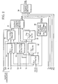
- FIG. 1 is a diagram showing the overall structure of a power transmission system for four-wheel drive vehicle according to the first embodiment.
- An automatic transmission 2 is connected to a transverse-mounted engine 1 (power source).
- a ring gear 3a of a front differential gear unit 3 (hereinafter referred to as front differential) engages with an output gear 2a of the automatic transmission 2.
- Left and right side gears 3b of the front differential 3 are connected with the left and right front wheels 5a, each by a drive shaft 4, so that power from the engine 1 is transmitted to the front wheels 5a via the front differential 3.
- a ring gear 6a of a power-take-off unit 6 (hereinafter referred to as PTU) is connected with a differential case 3c for the front differential 3, and a pinion gear 7a at the front end of a front propeller shaft 71 engages with the ring gear 6a.
- the automatic transmission 2, the front differential 3 and the PTU 6 are arranged in a common casing.
- An electronic controlled coupling 8 (power transmission mechanism) is provided between a rear part of the front propeller shaft 71 and a rear part of a rear propeller shaft 72.
- a pinion gear 7b at the rear end of the propeller shaft 72 engages with a ring gear 9a of a rear differential gear unit 9 (hereinafter referred to as rear differential).
- Left and right side gears 9b of the rear differential 9 are connected with the left and right rear wheels 5b, each by a drive shaft 10.
- the electronic controlled coupling 8 can control power transmitted to the rear differential 9 by controlling power transmitted from the front propeller shaft 71 to the rear propeller shaft 72 by adjusting the engaging force of an electromagnetic clutch 8a provided therein.
- the ratio of the power from the engine 1 supplied to the front wheels 5a to that supplied to the rear wheels 5b can be adjusted to any value between 100:0 and 50:50, for example.
- the LSD 9 includes a torque-sensitive differential limiting mechanism 9c for producing a differential limiting force depending on a torque supplied via the rear propeller shaft 72 and thereby limiting differential motion between the left and right wheels.
- a torque-sensitive differential limiting mechanism 9c for producing a differential limiting force depending on a torque supplied via the rear propeller shaft 72 and thereby limiting differential motion between the left and right wheels.
- a known structure such as a helical gear type structure or a cam type structure is used.
- an ECU for four-wheel drive 11 (power transmission control means) is provided, in addition to an engine control ECU, a shift control ECU, an ABS control ECU, etc.
- the ECU for four-wheel drive 11 comprises an input/output unit, memory (ROM, RAM, etc.) for storing control programs, control maps, etc., a central processing unit (CPU), a timer counter, etc.
- a longitudinal acceleration sensor 12 for detecting the longitudinal acceleration Gx of the vehicle
- a lateral acceleration sensor 13 for detecting the lateral acceleration Gy of the vehicle
- a yaw rate sensor 14 turning state detecting means for detecting the yaw rate Yr (actual yaw rate) of the vehicle
- wheel speed sensors 15a to 15d for detecting the wheel speeds Vfl, Vfr, Vrl, Vrr of the individual wheels of the vehicle
- a steering angle sensor 16 for detecting the steering angle St
- a brake sensor 17 for detecting brake operation information Bk
- a parking brake sensor 18 for detecting parking brake operation information Pbk.
- the engine control ECU 19 and the ABS control ECU 20 are connected to the input side of the ECU for four-wheel drive 11.
- various devices including the above-mentioned electromagnetic clutch 8a of the electronic controlled coupling 8 are connected.
- the ECU for four-wheel drive 11 controls the engaging force of the electromagnetic clutch 8a of the electronic controlled coupling 8 based on detection information from the above-mentioned various sensors.
- This control is performed not only for purposes general for the electronic controlled on-demand four-wheel drive vehicle, such as appropriate power distribution between the front wheels 5a and the rear wheels 5b to achieve ease of turning at an early stage of steering, restriction of slip in rapid acceleration, and stability in deceleration.
- this control is performed also for controlling the input torque supplied to the rear differential 9 to adjust the differential limiting force of the rear differential 9 to thereby relieve oversteer and understeer in the vehicle's turning. The latter control is required while the vehicle is turning.
- the former control switches to the latter control.
- the former control is performed.
- the detailed explanation of the former control will be omitted since it is similar to that disclosed in Japanese Unexamined Patent Publication No. 2002-127772 ( EP1203688A2 ) mentioned above as prior art, for example.
- the latter control will be described in detail below.
- An input torque to be supplied to the rear differential 9 is calculated as a rear-wheel output torque Tout according to the procedure shown in the block diagram of FIG. 2 .
- vehicle constants which are specific to individual vehicles, are used in addition to detection information from the above-mentioned various sensors.
- the maximum torque Tmax maximum power transmission amount
- Lsd differential-limiting-force against input-torque characteristic
- vehicle factors Sv for example, the vehicle weight W, the wheel base L, etc.
- the longitudinal acceleration Gx detected by the longitudinal acceleration sensor 12 and the wheel speeds Vfl, Vfr, Vrl, Vrr of the individual wheels detected by the wheel speed sensors 15a to 15d are fed to a body speed calculating section 31.
- the body speed calculating section 31 calculates the body speed Vb based on the information fed.
- the body speed Vb for example a procedure disclosed in Japanese Patent No. 3063628 is employed.
- the body speed Vb is calculated based on the wheel speed of the third fastest wheel of the four, which is, for example, the wheel speed of the rear inner wheel when the vehicle is turning.
- the body speed Vb is calculated based on the longitudinal acceleration Gx.
- the body speed Vb calculated by the body speed calculating section 31 and the steering angle St detected by the steering angle sensor 16 are fed to a reference yaw rate calculating section 32.
- the reference yaw rate Yrs obtained means an ideal yaw rate in the vehicle turning with the current body speed Vb and steering angle St.
- the reference yaw rate Yrs calculated by the reference yaw rate calculating section 32 and the actual yaw rate Yr detected by the yaw rate sensor 14 are fed to a target torque setting section 33.
- the target torque setting section 33 calculates a target torque Ttgt (target transmission amount) to be supplied to the rear differential 9, based on the information fed.
- the target torque Ttgt is calculated as an input torque required to be supplied to the rear differential 9 in order to change the yawing moment acting on the vehicle to correct the actual yaw rate Yr to the reference yaw rate Yrs. Specifically, as a map in FIG.
- the target torque Ttgt is set to zero in this region.
- the target torque Ttgt is set to increase in proportion as the absolute value of the difference increases.
- the longitudinal acceleration Gx detected by the longitudinal acceleration sensor 12, the lateral acceleration Gy detected by the lateral acceleration sensor 13, the steering angle St detected by the steering angle sensor 16, the yaw rate Yr detected by the yaw rate sensor 14 and the body speed Vb calculated by the body speed calculating section 31 are fed to a coefficient-of-friction-on-road estimating section 34.
- the coefficient-of-friction-on-road estimating section 34 estimates the coefficient of friction on a road Myu based on the information fed.
- the estimated value for the lateral acceleration is calculated from the vehicle speed in turning, the steering angle, etc., according to an arithmetic expression. Then, based on the ratio between the estimated value for the lateral acceleration thus calculated and the actual measurement value for the lateral acceleration, namely the value detected by the sensor, the coefficient of friction on the road is obtained.
- the ratio of the estimated value to the actual measurement value for the lateral acceleration is approximately equal to 1, it is considered that the vehicle will not skid and that the coefficient of friction on the road is high.
- the ratio is less than 1 and the vehicle is skidding, it is considered that the coefficient of friction on the road is one corresponding to this ratio.
- the vehicle factors Sv as vehicle constants, the longitudinal acceleration Gx detected by the longitudinal acceleration sensor 12 and the lateral acceleration Gy detected by the lateral acceleration sensor 13 are fed to an inner-wheel load calculating section 35.
- the inner-wheel load calculating section 35 calculates a rear-inner-wheel load Wri based on the information fed.
- the rear-inner-wheel load Wri means a load exerted on the rear inner wheel, namely the rear wheel located inside in the vehicle's turning, and is calculated in the procedure described below.
- ⁇ Wx W ⁇ Gx ⁇ hg / L
- W the vehicle weight
- hg the height of gravitational center
- L the wheel base
- the coefficient of friction on the road Myu estimated by the coefficient-of-friction-on-road estimating section 34, the rear-inner-wheel load Wri calculated by the inner-wheel load calculating section 35, and the LSD characteristic Lsd fed as a vehicle constant are fed to a minimum torque calculating section 36.
- the minimum torque calculating section 36 calculates a minimum torque Tc (predetermined value, critical amount for power transmitted) based on the information fed.
- Tc critical amount for power transmitted
- FIG. 3 is an illustration showing how driving forces are exerted via the left and right rear wheels 5b when the vehicle is turning.
- the load on the left rear wheel 5b located outside in turning increases while the load on the right rear wheel 5b located inside in turning decreases.
- the power supplied to the rear differential 9 via the electronic controlled coupling 8 is distributed between the left and right rear wheels 5b according to the LSD characteristic Lsd.
- torque is transferred from the wheel located outside in turning and revolving at higher speed, to the wheel located inside in turning and revolving at lower speed, by means of the toque-sensitive differential limiting mechanism 9c, so that a greater driving force is exerted via the right rear wheel 5b.
- the minimum torque Tc calculated by the minimum torque calculating section 36, the reference yaw rate Yrs calculated by the reference yaw rate calculating section 32, the target torque Ttgt calculated by the target torque setting section 33, the maximum torque Tmax that can be transmitted to the rear differential 9, which is fed as a vehicle constant, and the yaw rate Yr detected by the yaw rate sensor 14 are fed to an output torque setting section 37.
- the output torque setting section 37 calculates a rear-wheel output torque Tout to be supplied to the rear differential 9 via the electronic controlled coupling 8, based on the information fed.
- the rear-wheel output torque Tout is set to the target torque Ttgt.
- the rear-wheel output torque Tout is set in different ways, in accordance with the relation in magnitude between the maximum torque Tmax and the minimum torque Tc and the turning state of the vehicle (oversteer or understeer).
- the turning state is not considered on the basis of neutral steer. It is considered as a direction in which the actual yaw rate Yr deviates from the reference yaw rate Yrs.
- the rear-wheel output torque Tout is set to be between the minimum torque Tc and the maximum torque Tmax.
- the target torque Ttgt is calculated to be less than the minimum torque Tc
- the rear-wheel output torque Tout is set to the minimum torque Tc.
- the target torque Ttgt is calculated to be between the minimum torque Tc and the maximum torque Tmax
- the rear-wheel output torque Tout is set to the target torque Ttgt.
- the target torque Ttgt is calculated to be greater than the maximum torque Tmax
- the rear-wheel output torque Tout is set to the maximum torque Tmax.
- the rear-wheel output torque Tout is set to be less than the minimum torque Tc.
- the target torque Ttgt is calculated to be less than the minimum torque Tc
- the rear-wheel output torque Tout is set to the target torque Ttgt.
- the target torque Ttgt is calculated to be equal to or greater than the minimum torque Tc
- the rear-wheel output Tout is set to a value less than the minimum torque Tc.
- the rear-wheel output torque Tout is limited to zero, considering that the yawing moment acting on the vehicle cannot be corrected.
- the rear-wheel output torque Tout is set to be less than the maximum torque Tmax.
- the target torque Ttgt is calculated to be less than the maximum torque Tmax
- the rear-wheel output torque Tout is set to the target torque Ttgt.
- the upper limit of the setting range for the ideal rear-wheel output torque Tout is the minimum torque Tc.
- the rear-wheel output torque Tout that can be produced is limited to the maximum torque Tmax at most.
- the rear-wheel output torque Tout is set to the maximum torque Tmax at most. As a result, the oversteer of the vehicle is relieved.
- the wheel speeds Vfl, Vfr, Vrl, Vrr of the individual wheels are fed to a front and rear wheel speed calculating section 38.
- the front and rear wheel speed calculating section 38 calculates a front wheel speed Vf and a rear wheel speed Vr based on the information fed, according to expressions (5) and (6):
- Vf Vfl + Vfr / 2
- Vr Vrl + Vrr / 2
- the output limiting section 39 feeds the rear-wheel output torque Tout as it is when none of conditions 1) to 5) below are met, and limits the rear-wheel output torque Tout to zero and feeds it when any of conditions 1) to 5) is met.
- condition 1) When condition 1) is met, power cannot be transmitted from the front propeller shaft 71 to the rear propeller shaft 72, and hence power from the engine 1 cannot be supplied to the rear wheels 5b via the electronic controlled coupling 8. This means that the input torque supplied to the rear differential 9 cannot be controlled, which means that the yawing moment cannot be corrected utilizing the characteristic of the torque-sensitive LSD 9. Thus, the control is suspended.
- condition 2 When condition 2) is met, it is impossible to supply the rear-wheel output torque Tout greater than the engine torque Te to the rear differential 9. Hence, there is a risk that the turning behavior of the vehicle deteriorates because a differential limiting force appropriate to the driving state of the vehicle cannot be produced. Thus, the control is suspended.
- the engaging force of the electronic controlled coupling 8 is controlled. Specifically, from a map not shown, the duty ratio is set to a value corresponding to the rear-wheel output torque Tout, and the electromagnetic clutch 8a is excited based on the duty ratio to thereby control the engaging force of the electronic controlled coupling 8. As a result, a torque corresponding to the rear-wheel output torque Tout is supplied to the rear differential 9. Based on this controlled supply of the torque, the torque-sensitive differential limiting mechanism 9c exerts a differential limiting force on the rear differential 9 according to the characteristic shown in FIG. 3 .
- a yawing moment having such direction that promotes the turning of the vehicle is produced to relieve the understeer to improve the turning behavior.
- a yawing moment having such direction that hinders the turning of the vehicle is produced to relieve the oversteer to improve the stability.
- the power transmission system for four-wheel drive vehicle in this embodiment functions like the braking force control device and the traction control device, which are provided to control general turning characteristics when the vehicle is turning. Hence, these devices can be omitted.
- the structure of this power transmission system is basically the same as the usual structure for the electronic controlled on-demand four-wheel drive vehicle arranged such that part of power from the engine 1 driving the front wheels 5a is supplied to the rear wheels 5b via the electronic controlled coupling 8. It is simple, requiring no addition but the torque sensitive LSD 9 and the control by the ECU for four-wheel drive 11 shown in FIG. 2 .
- this power transmission system can control the turning characteristics of the vehicle appropriately, avoiding increase in vehicle weight and significant increase in production cost.
- the output torque setting section 37 determines whether the vehicle is in understeer state or oversteer state, from the actual yaw rate Yr and the reference yaw rate Yrs, and sets the rear-wheel output torque Tout based on the result of determination. Hence, a yawing moment having a direction appropriate to the turning state of the vehicle can be always produced, which makes it possible to control the turning characteristics of the vehicle more appropriately.
- the output torque setting section 37 sets the rear-wheel output torque Tout based on the target torque Ttgt obtained from the actual yaw rate Yr and the reference yaw rate Yrs, which is an ideal value for the yaw rate according to the driving state of the vehicle.
- the electronic controlled coupling 8 can be controlled in the manner reflecting the driving state of the vehicle. This also contributes to appropriate control on the turning characteristics of the vehicle.
- the yawing moment acting on the vehicle is changed to hinder the turning of the vehicle or promote the turning of the vehicle by making the rear inner wheel of the turning vehicle slip or grip the road, and the output torque setting section 37 sets the rear-wheel output torque Tout considering the minimum torque Tc required to make the rear inner wheel of the turning vehicle slip as a critical torque.
- the differential limiting force may be controlled within the grip region for the wheel located inside in turning.
- the greater the differential limiting force of the rear differential 9 is the greater torque is supplied to the rear inner wheel, so that a yawing moment having such direction that hinders the turning of the vehicle is produced.
- the differential limiting force is decreased by decreasing an input torque supplied to the rear differential 9.
- the differential limiting force is increased by increasing an input torque supplied to the rear differential 9. This way of control has the effects similar to those produced by the above embodiment.
- the output torque setting section 37 sets the rear-wheel output torque Tout, considering the maximum torque Tmax that can be transmitted to the rear differential 9, in addition to the target torque Ttgt and the minimum torque Tc. This prevents the rear-wheel output torque Tout being inappropriately set to a value greater than the maximum torque Tmax, and thereby prevents inappropriate control on the electronic controlled coupling 8.
- the output limiting section 39 prohibits the supply of a torque to the rear differential 9 based on conditions 1) to 5) provided in advance. For example, when it is impossible to supply appropriate power to the rear wheels 5b because of revolution difference between the front wheels 5a and the rear wheels 5b or shortage of the engine torque Te, the control is suspended. Hence, problems that may happen when power is transmitted in an inappropriate situation like this are prevented.
- the present invention is embodied as a power transmission system for a hybrid four-wheel drive vehicle in which a motor for driving the rear wheels is added to a front-engine/front-drive vehicle.
- many elements are the same in structure as in the first embodiment. Hence, the description below will be focused on differences, while the same elements will be denoted by the same reference numerals and the description thereof will be omitted.
- FIG. 5 is a diagram showing the overall structure of a power transmission system for four-wheel drive vehicle according to the second embodiment.
- the front-wheel side is quite similar in structure to that for a front-engine/front-drive vehicle. Power from an engine 1 is transmitted to left and right front wheels 5a via an automatic transmission 2, a front differential 3 and drive shafts 4.
- a motor 51 (second power source) for driving rear wheels 5b is provided in a rear part of the vehicle, and a reduction gear mechanism 52 is connected with an output shaft 51a of the motor 51.
- An output gear 52a of the reduction gear mechanism 52 engages with a ring gear 9a of a rear differential 9 including a torque-sensitive differential limiting mechanism 9c, and left and right side gears 9b of the rear differential 9 are connected with left and right rear wheels 5b, each by a drive shaft 10.
- power supplied to the front wheels 5a can be adjusted within the limits of the engine output, while power supplied to the rear wheels 5b can be adjusted within the limits of the motor output.
- an ECU for four-wheel drive 11 sets a rear-wheel output torque Tout according to the procedure shown in FIG. 2 as in the first embodiment, and controls the output of the motor 51 based on the rear-wheel output torque Tout, in place of controlling the engaging force of the electronic controlled coupling 8.
- an input torque supplied from the motor 51 to the rear differential 9 is controlled independently of the engine 1 on the front wheel 5a side. Consequently, problems with the supply of power to the rear wheels 5b which may happen in the first embodiment under the conditions 1) and 2) do not happen.
- the output limitation based on these conditions is not applied to the second embodiment.
- the maximum torque Tmax a maximum output torque that the motor 51 can supply is used.
- the turning characteristics of the vehicle can be controlled appropriately by adjusting the differential limiting force of the rear differential 9 by adjusting the input torque supplied to the rear differential 9, like the first embodiment.
- the structure is simple only with the motor 51 for driving the rear wheels and the reduction gear mechanism 52 added to the front-engine/front-drive vehicle, and the braking force control device and the traction control device can be omitted. Hence, increase in vehicle weight and significant increase in production cost can be avoided.
- the present invention is not limited to these embodiments.
- the invention in the first embodiment in which the invention is applied to an electronic controlled on-demand four-wheel drive vehicle based on a front-engine/front-drive vehicle and in the second embodiment in which the invention is applied to a hybrid four-wheel drive vehicle with a motor 51 for driving the rear wheels added to a front-engine/front-drive vehicle, an appropriate yawing moment is made to act on the vehicle by adjusting the differential limiting force of the rear differential 9.
- the differential limiting force is adjusted not on the rear wheel 5b side but on the front wheel 5a side.
- the invention can be applied to an electronic controlled on-demand four-wheel drive vehicle based on a front-engine/rear-drive vehicle or a hybrid four-wheel drive vehicle with a motor for driving the front wheels added to a front-engine/rear-drive vehicle, to adjust the differential limiting force of the front differential by controlling an input torque supplied to the front differential.
- these embodiments are arranged to set the target torque Ttgt to be supplied to the rear differential 9 (or the front differential), based on the reference yaw rate Yrs and the actual yaw rate Yr.
- the present invention is not limited to this. It can be arranged to set the target torque Ttgt according to running states such as the body speed Vb calculated by the body speed calculating section 31, the lateral acceleration Gy detected by the lateral acceleration sensor 13, and a calculated lateral acceleration obtained from the steering angle St detected by the steering angle sensor 16 and the body speed Vb, or driving states such as the body speed Vb, the steering angle St and the throttle position (accelerator position).
Landscapes
- Engineering & Computer Science (AREA)
- Chemical & Material Sciences (AREA)
- Combustion & Propulsion (AREA)
- Transportation (AREA)
- Mechanical Engineering (AREA)
- Arrangement And Driving Of Transmission Devices (AREA)
- Arrangement And Mounting Of Devices That Control Transmission Of Motive Force (AREA)
- Hybrid Electric Vehicles (AREA)
- Control Of Driving Devices And Active Controlling Of Vehicle (AREA)
- Control Of Vehicle Engines Or Engines For Specific Uses (AREA)
Claims (13)
- Système de transmission de puissance pour un véhicule à quatre roues motrices agencé de telle manière qu'une puissance en provenance d'une source de puissance ayant au moins une unité de puissance (1) est toujours transmise vers une première paire de roues qui est l'une de deux paire consistant en une paire de roues avant (5a) et une paire de roues arrière (5b), comprenant :un mécanisme de transmission de puissance (8) placé dans le véhicule pour sortir une partie de la puissance qui est sortie depuis la source de puissance ;des moyens de commande de transmission de puissance (11) pour commander le mécanisme de transmission de puissance (8) pour régler la puissance (Tout) sortie depuis le mécanisme de transmission de puissance (8) ; etune unité de différentiel (9) agencée entre les roues gauche et droite dans une seconde paire de roues qui est l'autre des deux paires, caractérisé en ce que l'unité de différentiel distribue la puissance (Tout) qui est sortie depuis le mécanisme de transmission de puissance (8) entre les roues gauche et droite dans la seconde paire, moyennant quoil'unité de différentiel (9) est une unité de différentiel sensible au couple avec une fonction de limitation différentielle pour produire une force de limitation différentielle entre les roues gauche et droite dans la seconde paire, selon la puissance qui lui est transmise, etles moyens de commande de transmission de puissance (11) commandent la puissance (Tout) transmise depuis le mécanisme de transmission de puissance (8) vers l'unité de différentiel (9) selon un état de conduite du véhicule.
- Système de transmission de puissance pour un véhicule à quatre roues motrices selon la revendication 1, caractérisé en ce queles moyens de commande de transmission de puissance (11) incluent des moyens de détection d'état de virage (14) pour détecter un état de virage du véhicule et commande le mécanisme de transmission de puissance (8) selon l'état de virage détecté par les moyens de détection d'état de virage (14).
- Système de transmission de puissance pour un véhicule à quatre roues motrices selon la revendication 2, caractérisé en ce queles moyens de commande de transmission de puissance (11) diminuent la puissance (Tout) transmise à l'unité de différentiel (9) pour produire un moment de lacet ayant une direction telle qu'il favorise le virage du véhicule, et augmentent la puissance (Tout) transmise à l'unité de différentiel (9) pour produire un moment de lacet ayant une direction telle qu'il gêne le virage du véhicule.
- Système de transmission de puissance pour un véhicule à quatre roues motrices selon la revendication 2, caractérisé en ce que :les moyens de commande de transmission de puissance (11) augmentent la puissance (Tout) transmise à l'unité de différentiel (9) pour produire un moment de lacet ayant une direction telle qu'il favorise le virage du véhicule, et diminuent la puissance (Tout) transmise à l'unité de différentiel (9) pour produire un moment de lacet ayant une direction telle qu'il gêne le virage du véhicule.
- Système de transmission de puissance pour un véhicule à quatre roues motrices selon la revendication 2, caractérisé en ce queles moyens de commande de transmission de puissance (11) règlent la puissance (Tout) transmise à l'unité de différentiel (9) pour être supérieure ou égale à une valeur prédéterminée (Tc) pour produire un moment de lacet ayant une direction telle qu'il favorise le virage du véhicule, et règlent la puissance (Tout) transmise à l'unité de différentiel (9) pour être inférieure à une valeur prédéterminée (Tc) pour produire un moment de lacet ayant une direction telle qu'il gêne le virage du véhicule.
- Système de transmission de puissance pour un véhicule à quatre roues motrices selon les revendications 2 à 5, caractérisé en ce queles moyens de commande de transmission de puissance (11) commandent le mécanisme de transmission de puissance (8) selon une quantité de transmission de puissance cible (Ttgt) qui est réglée selonun état de conduite et/ou un état d'avance du véhicule.
- Système de transmission de puissance pour un véhicule à quatre roues motrices selon la revendication 6, caractérisé en ce queles moyens de commande de transmission de puissance (11) règlent la quantité de transmission de puissance cible (Ttgt) selon une amplitude de mouvement de lacet réelle (Yr) du véhicule et une amplitude de mouvement de lacet cible (Yrs) qui est réglée selon un état de conduite du véhicule.
- Système de transmission de puissance pour un véhicule à quatre roues motrices selon la revendication 5, caractérisé en ce queladite valeur prédéterminée est une quantité de transmission de puissance critique (Tc) qui est une quantité de puissance devant être transmise à l'unité de différentiel (9) afin de produire un moment de lacet qui favorise le virage du véhicule, par la force de limitation différentielle, quand le véhicule vire.
- Système de transmission de puissance pour un véhicule à quatre roues motrices selon la revendication 8, caractérisé en ce queles moyens de commande de transmission de puissance (11) règlent une quantité de transmission de puissance cible (Ttgt) selon au moins un état de conduite ou un état d'avance du véhicule, et commandent le mécanisme de transmission de puissance (8) selon l'état de virage du véhicule, la quantité de transmission de puissance cible (Ttgt), et la quantité de transmission de puissance critique (Tc).
- Système de transmission de puissance pour un véhicule à quatre roues motrices selon la revendication 9, caractérisé en ce queles moyens de commande de transmission de puissance (11) commandent le mécanisme de transmission de puissance (8) selon l'état de virage du véhicule, la quantité de transmission de puissance cible (Ttgt), la quantité de transmission de puissance critique (Tc), et une quantité de transmission de puissance maximum (Tmax) que le mécanisme de transmission de puissance (8) peut transmettre.
- Système de transmission de puissance pour un véhicule à quatre roues motrices selon les revendications 1 à 10, caractérisé en ce quele mécanisme de transmission de puissance (8) transmet une partie de la puissance depuis une source de puissance (1) de la puissance fournie à la première paire de roues, à l'unité de différentiel (9).
- Système de transmission de puissance pour un véhicule à quatre roues motrices selon la revendication 11, caractérisé en ce queles moyens de commande de transmission de puissance (11) empêchent la transmission de puissance vers l'unité de différentiel (9) quand une vitesse de rotation (Vf) de la première paire de roues est inférieure à une vitesse de rotation (Vr) de la seconde paire de roues, ou quand la puissance de sortie (Te) fournie depuis la source de puissance (1) est inférieure à une quantité (Tout) de puissance réglée pour être transmise à l'unité de différentiel (9).
- Système de transmission de puissance pour un véhicule à quatre roues motrices selon les revendications 1 à 10, caractérisé en ce quela source de puissance comprend une première unité de puissance (1) et une seconde unité de puissance (51), dans lequella puissance venant de la première unité de puissance (1) est transmise à la première paire de roues, et la puissance venant la seconde unité de puissance (51) est transmise à l'unité de différentiel (9).
Applications Claiming Priority (2)
| Application Number | Priority Date | Filing Date | Title |
|---|---|---|---|
| JP2003406021A JP4386171B2 (ja) | 2003-12-04 | 2003-12-04 | 4輪駆動車の動力伝達装置 |
| JP2003406021 | 2003-12-04 |
Publications (3)
| Publication Number | Publication Date |
|---|---|
| EP1538017A2 EP1538017A2 (fr) | 2005-06-08 |
| EP1538017A3 EP1538017A3 (fr) | 2005-12-07 |
| EP1538017B1 true EP1538017B1 (fr) | 2008-09-17 |
Family
ID=34463995
Family Applications (1)
| Application Number | Title | Priority Date | Filing Date |
|---|---|---|---|
| EP04028469A Expired - Lifetime EP1538017B1 (fr) | 2003-12-04 | 2004-12-01 | Transmission pour un véhicule à quatre roues motrices |
Country Status (6)
| Country | Link |
|---|---|
| US (1) | US7325640B2 (fr) |
| EP (1) | EP1538017B1 (fr) |
| JP (1) | JP4386171B2 (fr) |
| KR (1) | KR100590400B1 (fr) |
| CN (1) | CN100346998C (fr) |
| DE (1) | DE602004016610D1 (fr) |
Families Citing this family (54)
| Publication number | Priority date | Publication date | Assignee | Title |
|---|---|---|---|---|
| JP3843966B2 (ja) * | 2003-06-05 | 2006-11-08 | アイシン・エィ・ダブリュ株式会社 | ハイブリッド型車両駆動制御装置、ハイブリッド型車両駆動制御方法及びそのプログラム |
| JP2006007984A (ja) * | 2004-06-25 | 2006-01-12 | Fuji Heavy Ind Ltd | 4輪駆動車の制御装置 |
| SE0402539D0 (sv) * | 2004-10-21 | 2004-10-21 | Haldex Traction Ab | All wheel drive system |
| CA2600613C (fr) * | 2005-03-29 | 2016-10-25 | Martin Roche | Capteur de detection de parametres corporels et procede de detection de parametres corporels |
| US11457813B2 (en) | 2005-03-29 | 2022-10-04 | Martin W. Roche | Method for detecting body parameters |
| US20110213221A1 (en) | 2005-03-29 | 2011-09-01 | Roche Martin W | Method for Detecting Body Parameters |
| JP4663405B2 (ja) * | 2005-05-27 | 2011-04-06 | 川崎重工業株式会社 | レジャービィークル |
| JP4935022B2 (ja) * | 2005-08-23 | 2012-05-23 | 日産自動車株式会社 | 車両の左右トルク配分制御装置 |
| US7810601B2 (en) * | 2005-10-14 | 2010-10-12 | Team Industries, Inc. | All terrain or utility vehicle having selectable drive configurations and method therefore |
| GB0603452D0 (en) * | 2006-02-22 | 2006-04-05 | Ford Global Tech Llc | Hybrid motor vehicle driveline |
| JP4844720B2 (ja) | 2006-03-07 | 2011-12-28 | 三菱自動車工業株式会社 | 車両の差動制限制御装置 |
| JP4730543B2 (ja) * | 2006-03-29 | 2011-07-20 | 三菱自動車工業株式会社 | 車両の駆動力分配制御装置 |
| JP4662060B2 (ja) * | 2006-03-29 | 2011-03-30 | 三菱自動車工業株式会社 | 車両の駆動力分配制御装置 |
| JP2010516556A (ja) * | 2007-01-25 | 2010-05-20 | 本田技研工業株式会社 | 車両の安定性を改善するための車両システムの制御方法 |
| JP4798012B2 (ja) * | 2007-01-30 | 2011-10-19 | トヨタ自動車株式会社 | 車両用差動制限装置の制御装置 |
| JP4229193B2 (ja) | 2007-04-06 | 2009-02-25 | 三菱自動車工業株式会社 | 車両用差動制限装置 |
| JP2008302892A (ja) * | 2007-06-11 | 2008-12-18 | Aisin Seiki Co Ltd | 車両の駆動システム |
| JP5045280B2 (ja) * | 2007-07-10 | 2012-10-10 | 株式会社ジェイテクト | 駆動力伝達装置 |
| US8958965B2 (en) * | 2007-09-13 | 2015-02-17 | Ford Global Technologies Llc | System and method for managing a powertrain in a vehicle |
| KR100946492B1 (ko) | 2007-10-29 | 2010-03-10 | 현대자동차주식회사 | 4륜 구동 하이브리드 차량의 후륜 구동장치 |
| JP2009143292A (ja) * | 2007-12-12 | 2009-07-02 | Fuji Heavy Ind Ltd | 車両用運動制御装置 |
| JP5088255B2 (ja) * | 2008-07-14 | 2012-12-05 | トヨタ自動車株式会社 | 車両運動制御システム |
| CA2677392C (fr) * | 2008-09-09 | 2016-11-29 | Magna Powertrain Usa, Inc. | Unite de prise de force avec couplage actif et systeme de deconnexion hypoide |
| KR100986084B1 (ko) | 2008-10-21 | 2010-10-07 | 현대자동차주식회사 | 4륜 구동차량의 토크 제어장치 및 방법 |
| US20110319213A1 (en) | 2009-03-09 | 2011-12-29 | Magna Powertrain Of America, Inc. | All-wheel drive with active dry disconnect system |
| JP5256130B2 (ja) * | 2009-06-19 | 2013-08-07 | 富士重工業株式会社 | 4輪駆動車のタイヤ力制御装置 |
| US20110269595A1 (en) * | 2010-04-30 | 2011-11-03 | American Axle & Manufacturing Inc. | Control strategy for operating a locking differential |
| JP5299368B2 (ja) * | 2010-07-09 | 2013-09-25 | 日産自動車株式会社 | 車両の左右輪駆動力配分制御装置 |
| GB2488529A (en) * | 2011-02-18 | 2012-09-05 | Land Rover Uk Ltd | Vehicle with power transfer clutch actuator which reduces mode chattering |
| GB2490427B (en) * | 2011-04-28 | 2014-04-23 | Jaguar Land Rover Ltd | Vehicle and method of controlling a vehicle |
| US20130231837A1 (en) * | 2012-03-02 | 2013-09-05 | GM Global Technology Operations LLC | Electronic control of a limited slip differential |
| US8795126B2 (en) * | 2012-05-14 | 2014-08-05 | American Axle & Manufacturing, Inc. | Disconnectable driveline for all-wheel drive vehicle |
| JP5483770B2 (ja) * | 2012-09-21 | 2014-05-07 | 富士重工業株式会社 | 4輪駆動車の制御装置 |
| DE102012020908A1 (de) * | 2012-10-24 | 2014-05-08 | Audi Ag | Verfahren und System zum Betreiben eines Antriebsstrangs eines Kraftwagens |
| JP6083202B2 (ja) * | 2012-11-15 | 2017-02-22 | 株式会社ジェイテクト | 四輪駆動車 |
| US20140324290A1 (en) * | 2013-04-30 | 2014-10-30 | Ford Global Technologies, Llc | Traction and Cornering Properties of a Motor Vehicle |
| DE102013009540A1 (de) | 2013-06-07 | 2014-12-11 | Audi Ag | Antriebsvorrichtung für allradgetriebene Kraftfahrzeuge |
| BR112016019481B1 (pt) * | 2014-02-24 | 2023-04-18 | Mahindra And Mahindra Limited | Sistema para acondicionar um motor de veículo |
| GB2545261A (en) | 2015-12-11 | 2017-06-14 | Jaguar Land Rover Ltd | Control system and method of controlling a driveline |
| JP6298037B2 (ja) * | 2015-12-24 | 2018-03-20 | トヨタ自動車株式会社 | 駆動装置の制御システム |
| CN107487174A (zh) * | 2016-07-15 | 2017-12-19 | 宝沃汽车(中国)有限公司 | 混合动力汽车的四驱系统和四驱方法以及混合动力汽车 |
| JP6565871B2 (ja) * | 2016-11-15 | 2019-08-28 | トヨタ自動車株式会社 | 車両用4輪駆動装置の制御装置 |
| US10344844B2 (en) * | 2017-05-24 | 2019-07-09 | GM Global Technology Operations LLC | Method and system for controlling a limited slip differential |
| DE102017215700B4 (de) * | 2017-09-06 | 2022-09-29 | Audi Ag | Verfahren zum Betreiben eines Kraftfahrzeugs, insbesondere eines Kraftwagens |
| JP6836196B2 (ja) * | 2017-11-16 | 2021-02-24 | トヨタ自動車株式会社 | 四輪駆動車両の制御装置 |
| CN108081942B (zh) * | 2017-12-26 | 2024-10-25 | 阿尔特汽车技术股份有限公司 | 基于四驱越野车的电控集成式hev动力系统 |
| US11433869B2 (en) * | 2018-03-12 | 2022-09-06 | Gkn Automotive Limited | Controlling a drive torque and drive train assembly |
| JP6958473B2 (ja) | 2018-04-23 | 2021-11-02 | トヨタ自動車株式会社 | 4輪駆動車両 |
| JP7040383B2 (ja) * | 2018-09-25 | 2022-03-23 | トヨタ自動車株式会社 | 四輪駆動車両 |
| JP6814192B2 (ja) | 2018-11-26 | 2021-01-13 | 本田技研工業株式会社 | 車両制御装置、車両制御方法、およびプログラム |
| KR20210142057A (ko) * | 2020-05-15 | 2021-11-24 | 현대자동차주식회사 | 차량 선회 제어 장치, 그를 포함한 시스템 및 그 방법 |
| JP7704055B2 (ja) * | 2022-03-22 | 2025-07-08 | トヨタ自動車株式会社 | 車両の制御装置 |
| JP7746923B2 (ja) * | 2022-06-07 | 2025-10-01 | トヨタ自動車株式会社 | 駆動力制御装置 |
| FR3145896B1 (fr) | 2023-02-22 | 2026-01-16 | Renault Sas | Procédé de répartition de l’énergie électrique d’une batterie |
Family Cites Families (19)
| Publication number | Priority date | Publication date | Assignee | Title |
|---|---|---|---|---|
| JPH0618276Y2 (ja) | 1986-06-13 | 1994-05-11 | 日産自動車株式会社 | 路面摩擦係数検出装置 |
| US5265020A (en) * | 1990-04-20 | 1993-11-23 | Mazda Motor Corporation | Torque distribution control apparatus for four wheel drive |
| JP2851385B2 (ja) * | 1990-06-14 | 1999-01-27 | マツダ株式会社 | 4輪駆動車のトルク配分制御装置 |
| JP2917076B2 (ja) * | 1992-01-07 | 1999-07-12 | トヨタ自動車株式会社 | 4輪駆動車の自動変速機の制御装置 |
| US5301768A (en) * | 1992-05-04 | 1994-04-12 | Aisin Aw Co., Ltd. | Four-wheel drive torque transfer mechanism |
| JP3144717B2 (ja) * | 1992-09-17 | 2001-03-12 | 富士重工業株式会社 | 4輪駆動車のトルク配分制御方法 |
| US5450919A (en) * | 1993-01-12 | 1995-09-19 | Mazda Motor Corporation | Differential action control system of a vehicle |
| JPH0717277A (ja) * | 1993-07-07 | 1995-01-20 | Honda Motor Co Ltd | 車両のトルク分配制御装置 |
| JP3460281B2 (ja) * | 1993-12-17 | 2003-10-27 | マツダ株式会社 | 自動車の駆動力配分制御装置 |
| US5492194A (en) * | 1993-12-23 | 1996-02-20 | Borg-Warner Automotive, Inc. | On demand vehicle drive system |
| JP3409439B2 (ja) * | 1994-06-17 | 2003-05-26 | 日産自動車株式会社 | 左右輪と前後輪の駆動力配分総合制御装置 |
| JP3681786B2 (ja) * | 1995-05-01 | 2005-08-10 | 本田技研工業株式会社 | 前後輪駆動車両 |
| JP3063628B2 (ja) | 1996-07-05 | 2000-07-12 | 三菱自動車工業株式会社 | 車体速演算装置 |
| JPH10129288A (ja) * | 1996-10-31 | 1998-05-19 | Isuzu Motors Ltd | 四輪駆動車 |
| DE69724383T2 (de) * | 1996-11-13 | 2004-06-24 | Honda Giken Kogyo K.K. | System zur Kontrolle des Giermomentes in Fahrzeugen |
| JP3719116B2 (ja) * | 2000-08-30 | 2005-11-24 | トヨタ自動車株式会社 | 車輌の駆動力制御装置 |
| JP4456748B2 (ja) | 2000-10-27 | 2010-04-28 | 富士重工業株式会社 | 4輪駆動車の動力配分制御装置 |
| JP2003312289A (ja) * | 2002-04-23 | 2003-11-06 | Toyoda Mach Works Ltd | 4輪駆動車 |
| JP4317716B2 (ja) * | 2003-07-08 | 2009-08-19 | 株式会社ジェイテクト | 4輪駆動車の駆動力配分制御装置 |
-
2003
- 2003-12-04 JP JP2003406021A patent/JP4386171B2/ja not_active Expired - Fee Related
-
2004
- 2004-11-23 KR KR1020040096139A patent/KR100590400B1/ko not_active Expired - Fee Related
- 2004-12-01 DE DE602004016610T patent/DE602004016610D1/de not_active Expired - Lifetime
- 2004-12-01 EP EP04028469A patent/EP1538017B1/fr not_active Expired - Lifetime
- 2004-12-02 US US11/001,070 patent/US7325640B2/en not_active Expired - Lifetime
- 2004-12-03 CN CNB2004101001629A patent/CN100346998C/zh not_active Expired - Fee Related
Also Published As
| Publication number | Publication date |
|---|---|
| CN100346998C (zh) | 2007-11-07 |
| CN1644421A (zh) | 2005-07-27 |
| EP1538017A2 (fr) | 2005-06-08 |
| JP4386171B2 (ja) | 2009-12-16 |
| KR100590400B1 (ko) | 2006-06-19 |
| EP1538017A3 (fr) | 2005-12-07 |
| US20050121248A1 (en) | 2005-06-09 |
| KR20050054440A (ko) | 2005-06-10 |
| US7325640B2 (en) | 2008-02-05 |
| JP2005162097A (ja) | 2005-06-23 |
| DE602004016610D1 (de) | 2008-10-30 |
Similar Documents
| Publication | Publication Date | Title |
|---|---|---|
| EP1538017B1 (fr) | Transmission pour un véhicule à quatre roues motrices | |
| EP1203688B1 (fr) | Système de commande de la répartition d'une force motrice | |
| EP0314452B1 (fr) | Transmission de puissance pour un véhicule à quatre roues motrices | |
| US8548706B2 (en) | Device operable to control turning of vehicle | |
| US6564140B2 (en) | Vehicle dynamics control system and vehicle having the vehicle dynamics control system | |
| JP3617680B2 (ja) | 4輪駆動車のトラクション制御装置 | |
| US8285450B2 (en) | Differential limiting control device for vehicle | |
| EP1232900B1 (fr) | Procédé et dispositif de commande pour véhicule à quatre roues motrices | |
| US6587775B2 (en) | Driving force control system for four-wheel drive vehicles | |
| EP1686031B1 (fr) | Dispositif de commande d'un véhicule à quatre roues motrices | |
| EP1127726B1 (fr) | Dispositif de commande pour la distribution de la force motrice et méthode de contrôle pour un véhicule à quatre roues motrices | |
| EP2010407B1 (fr) | Systeme de commande d'un embrayage de transfert de couple dans un vehicule 4x4 | |
| US20040059494A1 (en) | Differential limiting control apparatus for a vehicle and the method thereof | |
| EP1400390A2 (fr) | Dispositif de commande de distribution de puissance pour véhicule à quatre roues motrices | |
| EP0313371B1 (fr) | Système de commande pour répartir la force motrice pour véhicule automibile à quatre roues motrices | |
| JP3827837B2 (ja) | 車両運動制御装置 | |
| JP5663368B2 (ja) | 車両の運転支援制御装置 | |
| JPH10138783A (ja) | 車両のヨーモーメント制御装置 | |
| JP4910361B2 (ja) | 車輌の駆動力制御装置 | |
| JP4784741B2 (ja) | 車輌の駆動力制御装置 | |
| JP2848107B2 (ja) | 車両用差動制限制御装置 | |
| JPH10181564A (ja) | 車両のトラクション制御装置 |
Legal Events
| Date | Code | Title | Description |
|---|---|---|---|
| PUAI | Public reference made under article 153(3) epc to a published international application that has entered the european phase |
Free format text: ORIGINAL CODE: 0009012 |
|
| AK | Designated contracting states |
Kind code of ref document: A2 Designated state(s): AT BE BG CH CY CZ DE DK EE ES FI FR GB GR HU IE IS IT LI LT LU MC NL PL PT RO SE SI SK TR |
|
| AX | Request for extension of the european patent |
Extension state: AL BA HR LV MK YU |
|
| PUAL | Search report despatched |
Free format text: ORIGINAL CODE: 0009013 |
|
| AK | Designated contracting states |
Kind code of ref document: A3 Designated state(s): AT BE BG CH CY CZ DE DK EE ES FI FR GB GR HU IE IS IT LI LT LU MC NL PL PT RO SE SI SK TR |
|
| AX | Request for extension of the european patent |
Extension state: AL BA HR LV MK YU |
|
| 17P | Request for examination filed |
Effective date: 20051215 |
|
| AKX | Designation fees paid |
Designated state(s): DE FR GB |
|
| 17Q | First examination report despatched |
Effective date: 20060407 |
|
| RAP1 | Party data changed (applicant data changed or rights of an application transferred) |
Owner name: MITSUBISHI JIDOSHA KOGYO KABUSHIKI KAISHA |
|
| GRAP | Despatch of communication of intention to grant a patent |
Free format text: ORIGINAL CODE: EPIDOSNIGR1 |
|
| GRAS | Grant fee paid |
Free format text: ORIGINAL CODE: EPIDOSNIGR3 |
|
| GRAA | (expected) grant |
Free format text: ORIGINAL CODE: 0009210 |
|
| AK | Designated contracting states |
Kind code of ref document: B1 Designated state(s): DE FR GB |
|
| REG | Reference to a national code |
Ref country code: GB Ref legal event code: FG4D |
|
| REF | Corresponds to: |
Ref document number: 602004016610 Country of ref document: DE Date of ref document: 20081030 Kind code of ref document: P |
|
| PLBE | No opposition filed within time limit |
Free format text: ORIGINAL CODE: 0009261 |
|
| STAA | Information on the status of an ep patent application or granted ep patent |
Free format text: STATUS: NO OPPOSITION FILED WITHIN TIME LIMIT |
|
| 26N | No opposition filed |
Effective date: 20090618 |
|
| REG | Reference to a national code |
Ref country code: FR Ref legal event code: PLFP Year of fee payment: 12 |
|
| REG | Reference to a national code |
Ref country code: FR Ref legal event code: PLFP Year of fee payment: 13 |
|
| REG | Reference to a national code |
Ref country code: FR Ref legal event code: PLFP Year of fee payment: 14 |
|
| PGFP | Annual fee paid to national office [announced via postgrant information from national office to epo] |
Ref country code: DE Payment date: 20181120 Year of fee payment: 15 |
|
| PGFP | Annual fee paid to national office [announced via postgrant information from national office to epo] |
Ref country code: GB Payment date: 20181128 Year of fee payment: 15 Ref country code: FR Payment date: 20181120 Year of fee payment: 15 |
|
| REG | Reference to a national code |
Ref country code: DE Ref legal event code: R119 Ref document number: 602004016610 Country of ref document: DE |
|
| GBPC | Gb: european patent ceased through non-payment of renewal fee |
Effective date: 20191201 |
|
| PG25 | Lapsed in a contracting state [announced via postgrant information from national office to epo] |
Ref country code: FR Free format text: LAPSE BECAUSE OF NON-PAYMENT OF DUE FEES Effective date: 20191231 Ref country code: GB Free format text: LAPSE BECAUSE OF NON-PAYMENT OF DUE FEES Effective date: 20191201 Ref country code: DE Free format text: LAPSE BECAUSE OF NON-PAYMENT OF DUE FEES Effective date: 20200701 |