EP1535012B1 - Arme a feu de poing a culasse verrouillee - Google Patents
Arme a feu de poing a culasse verrouillee Download PDFInfo
- Publication number
- EP1535012B1 EP1535012B1 EP03798134A EP03798134A EP1535012B1 EP 1535012 B1 EP1535012 B1 EP 1535012B1 EP 03798134 A EP03798134 A EP 03798134A EP 03798134 A EP03798134 A EP 03798134A EP 1535012 B1 EP1535012 B1 EP 1535012B1
- Authority
- EP
- European Patent Office
- Prior art keywords
- closure
- cartridge
- locking
- carrier
- bolt head
- Prior art date
- Legal status (The legal status is an assumption and is not a legal conclusion. Google has not performed a legal analysis and makes no representation as to the accuracy of the status listed.)
- Expired - Lifetime
Links
- 238000010304 firing Methods 0.000 claims description 71
- 230000033001 locomotion Effects 0.000 claims description 62
- 239000004429 Calibre Substances 0.000 claims 1
- 230000000284 resting effect Effects 0.000 claims 1
- 210000003128 head Anatomy 0.000 description 140
- 239000007789 gas Substances 0.000 description 70
- 210000000078 claw Anatomy 0.000 description 46
- 239000000872 buffer Substances 0.000 description 19
- 230000008719 thickening Effects 0.000 description 12
- 210000002414 leg Anatomy 0.000 description 11
- 230000035939 shock Effects 0.000 description 9
- 230000006835 compression Effects 0.000 description 7
- 238000007906 compression Methods 0.000 description 7
- 230000001133 acceleration Effects 0.000 description 5
- 229920001971 elastomer Polymers 0.000 description 5
- 239000002184 metal Substances 0.000 description 5
- 241001295925 Gegenes Species 0.000 description 4
- 206010053648 Vascular occlusion Diseases 0.000 description 4
- 230000001154 acute effect Effects 0.000 description 4
- 230000000295 complement effect Effects 0.000 description 4
- 230000008878 coupling Effects 0.000 description 4
- 238000010168 coupling process Methods 0.000 description 4
- 238000005859 coupling reaction Methods 0.000 description 4
- 230000000694 effects Effects 0.000 description 4
- 239000000806 elastomer Substances 0.000 description 4
- 230000007246 mechanism Effects 0.000 description 4
- 210000001331 nose Anatomy 0.000 description 4
- 230000007704 transition Effects 0.000 description 4
- 230000008901 benefit Effects 0.000 description 3
- 238000010276 construction Methods 0.000 description 3
- 238000011109 contamination Methods 0.000 description 3
- 210000000245 forearm Anatomy 0.000 description 3
- 238000004519 manufacturing process Methods 0.000 description 3
- 239000000843 powder Substances 0.000 description 3
- 230000009471 action Effects 0.000 description 2
- 238000004873 anchoring Methods 0.000 description 2
- 230000005540 biological transmission Effects 0.000 description 2
- 230000008859 change Effects 0.000 description 2
- 238000006243 chemical reaction Methods 0.000 description 2
- 208000037265 diseases, disorders, signs and symptoms Diseases 0.000 description 2
- 238000000605 extraction Methods 0.000 description 2
- 239000002223 garnet Substances 0.000 description 2
- 238000009434 installation Methods 0.000 description 2
- 238000000034 method Methods 0.000 description 2
- 230000003071 parasitic effect Effects 0.000 description 2
- 238000003825 pressing Methods 0.000 description 2
- 230000008569 process Effects 0.000 description 2
- 230000002441 reversible effect Effects 0.000 description 2
- 238000007789 sealing Methods 0.000 description 2
- 230000001960 triggered effect Effects 0.000 description 2
- 210000001364 upper extremity Anatomy 0.000 description 2
- 239000006096 absorbing agent Substances 0.000 description 1
- 230000002411 adverse Effects 0.000 description 1
- 230000009286 beneficial effect Effects 0.000 description 1
- 230000015572 biosynthetic process Effects 0.000 description 1
- 210000001217 buttock Anatomy 0.000 description 1
- 238000004140 cleaning Methods 0.000 description 1
- 238000006073 displacement reaction Methods 0.000 description 1
- 238000005755 formation reaction Methods 0.000 description 1
- 230000003993 interaction Effects 0.000 description 1
- JEIPFZHSYJVQDO-UHFFFAOYSA-N iron(III) oxide Inorganic materials O=[Fe]O[Fe]=O JEIPFZHSYJVQDO-UHFFFAOYSA-N 0.000 description 1
- 230000007257 malfunction Effects 0.000 description 1
- 239000000463 material Substances 0.000 description 1
- 230000010363 phase shift Effects 0.000 description 1
- IMACFCSSMIZSPP-UHFFFAOYSA-N phenacyl chloride Chemical compound ClCC(=O)C1=CC=CC=C1 IMACFCSSMIZSPP-UHFFFAOYSA-N 0.000 description 1
- 239000013641 positive control Substances 0.000 description 1
- 230000002028 premature Effects 0.000 description 1
- 230000000750 progressive effect Effects 0.000 description 1
- 230000009467 reduction Effects 0.000 description 1
- 238000010079 rubber tapping Methods 0.000 description 1
- 125000006850 spacer group Chemical group 0.000 description 1
- 239000000725 suspension Substances 0.000 description 1
- 239000003491 tear gas Substances 0.000 description 1
- 210000000216 zygoma Anatomy 0.000 description 1
Images


Classifications
-
- F—MECHANICAL ENGINEERING; LIGHTING; HEATING; WEAPONS; BLASTING
- F41—WEAPONS
- F41A—FUNCTIONAL FEATURES OR DETAILS COMMON TO BOTH SMALLARMS AND ORDNANCE, e.g. CANNONS; MOUNTINGS FOR SMALLARMS OR ORDNANCE
- F41A5/00—Mechanisms or systems operated by propellant charge energy for automatically opening the lock
- F41A5/18—Mechanisms or systems operated by propellant charge energy for automatically opening the lock gas-operated
- F41A5/26—Arrangements or systems for bleeding the gas from the barrel
-
- F—MECHANICAL ENGINEERING; LIGHTING; HEATING; WEAPONS; BLASTING
- F41—WEAPONS
- F41A—FUNCTIONAL FEATURES OR DETAILS COMMON TO BOTH SMALLARMS AND ORDNANCE, e.g. CANNONS; MOUNTINGS FOR SMALLARMS OR ORDNANCE
- F41A15/00—Cartridge extractors, i.e. devices for pulling cartridges or cartridge cases at least partially out of the cartridge chamber; Cartridge ejectors, i.e. devices for throwing the extracted cartridges or cartridge cases free of the gun
- F41A15/12—Cartridge extractors, i.e. devices for pulling cartridges or cartridge cases at least partially out of the cartridge chamber; Cartridge ejectors, i.e. devices for throwing the extracted cartridges or cartridge cases free of the gun for bolt-action guns
-
- F—MECHANICAL ENGINEERING; LIGHTING; HEATING; WEAPONS; BLASTING
- F41—WEAPONS
- F41A—FUNCTIONAL FEATURES OR DETAILS COMMON TO BOTH SMALLARMS AND ORDNANCE, e.g. CANNONS; MOUNTINGS FOR SMALLARMS OR ORDNANCE
- F41A19/00—Firing or trigger mechanisms; Cocking mechanisms
- F41A19/06—Mechanical firing mechanisms, e.g. counterrecoil firing, recoil actuated firing mechanisms
- F41A19/13—Percussion or firing pins, i.e. fixed or slidably-mounted striker elements; Mountings therefor
-
- F—MECHANICAL ENGINEERING; LIGHTING; HEATING; WEAPONS; BLASTING
- F41—WEAPONS
- F41A—FUNCTIONAL FEATURES OR DETAILS COMMON TO BOTH SMALLARMS AND ORDNANCE, e.g. CANNONS; MOUNTINGS FOR SMALLARMS OR ORDNANCE
- F41A3/00—Breech mechanisms, e.g. locks
- F41A3/12—Bolt action, i.e. the main breech opening movement being parallel to the barrel axis
- F41A3/36—Semi-rigid bolt locks, i.e. having locking elements movably mounted on the bolt or on the barrel or breech housing
- F41A3/44—Semi-rigid bolt locks, i.e. having locking elements movably mounted on the bolt or on the barrel or breech housing having sliding locking elements, e.g. balls, rollers
- F41A3/46—Semi-rigid bolt locks, i.e. having locking elements movably mounted on the bolt or on the barrel or breech housing having sliding locking elements, e.g. balls, rollers mounted on the bolt
-
- F—MECHANICAL ENGINEERING; LIGHTING; HEATING; WEAPONS; BLASTING
- F41—WEAPONS
- F41A—FUNCTIONAL FEATURES OR DETAILS COMMON TO BOTH SMALLARMS AND ORDNANCE, e.g. CANNONS; MOUNTINGS FOR SMALLARMS OR ORDNANCE
- F41A35/00—Accessories or details not otherwise provided for
- F41A35/06—Adaptation of guns to both right and left hand use
-
- F—MECHANICAL ENGINEERING; LIGHTING; HEATING; WEAPONS; BLASTING
- F41—WEAPONS
- F41A—FUNCTIONAL FEATURES OR DETAILS COMMON TO BOTH SMALLARMS AND ORDNANCE, e.g. CANNONS; MOUNTINGS FOR SMALLARMS OR ORDNANCE
- F41A5/00—Mechanisms or systems operated by propellant charge energy for automatically opening the lock
- F41A5/18—Mechanisms or systems operated by propellant charge energy for automatically opening the lock gas-operated
Definitions
- the invention relates to a large-caliber gas pressure supercharger with a central force introduction part which receives the rear end of the barrel and the locking abutment of the closure
- This gas pressure supercharger uses the principle of closure of a handgun with a locked closure and a closure carrier wherein the closure head is penetrated by a locking block which transversely is movable to the direction of movement of the closure and in the locking position engages over a large area locking projections.
- large caliber is meant in particular a rifle with a caliber or largest sleeve diameter of the cartridge of more than 15 mm.
- FR1266597 discloses a large caliber rifle according to the preamble of claim 1.
- a heavy missile such as a projectile, a sabot projectile, a shotgun, a gas body, or the like
- the gas pressure is comparatively low, especially in the front of the barrel.
- the cartridge diameter is greater than 15 mm, the shutter is large and long and thus heavy, so that the forces required to load through are large.
- the gas pressure since the gas pressure, as already mentioned, is low, the effective area of the gas piston must be large. Accordingly, the amount of gas that is withdrawn from the barrel during firing is also large.
- recoil loaders which, however, have the disadvantage of being particularly sensitive to differences in recoil.
- a large anchoring element has recently been provided with a large-caliber rifle for weight savings, to which all occurring forces should act as much as possible.
- the housing can then be carried out largely in the lightest plastic construction, since it is at most little burden.
- a gas piston device requires at the tapping point of the barrel, which usually interacts with the gas cylinder, another point of introduction of force and thus builds quite difficult.
- the invention is therefore the object of developing the aforementioned, large-caliber rifle to the effect that at least one of the problems mentioned above is at least partially mitigated.
- the invention is based on the object, a self loading rifle for large caliber.
- Long cartridge shotgun cartridge case with short cartridge case that is lightweight and reliable in transit.
- the barrel still has a gas removal opening in the force introduction part, and that a gas cylinder is firmly connected to the force introduction part, which is connected to the gas discharge opening, wherein the barrel 101 still in the force introduction part 104 has a gas removal opening 173 and wherein a gas cylinder 171 is fixedly connected to the force introduction part 104, which is connected to the gas removal opening 173.
- a tube is firmly connected to the closure carrier, the gas cylinder passes through and is penetrated as a receiving tube for a closing spring.
- the inner surface of the gas cylinder thus has an annular surface, and also the force takes place exactly centric on the closure carrier.
- the return spring for the closure the so-called closing spring, further penetrates the tube, so that the closure member forming the gas piston is also set back exactly centric and thus can not tilt.
- the gas cylinder viewed in terms of its diameter, can thus also build shorter than would otherwise be necessary.
- a rocker arm which is arranged in the closure head, engages on the one hand in the movement path of the closure carrier and on the other hand in the path of movement of the locking bolt and pulls out of its rest position, the locking bolt from the formations of the force introduction part in a movement of the closure carrier.
- Such a rocker arm is mounted for example on a pivot axis which is arranged transversely in the closure head.
- such a device can also be formed approximately by a compression spring which pushes out the locking bolt from its rest position when the closure carrier makes room.
- the invention differs from the effect that two recesses are formed transversely to the locking pin in the closure head, in each of which from behind a hole for a pressure pin and a spring pushing this forward are formed, that in one of the recesses a counter to the force of the pressure pin pivotable extractor is used, and that in the opposite recess as far as necessary a support member is immovably inserted, opposite to the extractor, the bottom of a cartridge or cartridge case laterally supported. Extractor and support element thus face each other (claim 1).
- the gas removal opening in the force introduction member eliminates its own, force-absorbing enclosure of the gas removal opening. At the same time this is brought far to the rear, where the gas pressure sufficient for unlocking and pressing a heavy closure with a long reload path.
- the barrel of the weapon according to the invention is preferably, as is common practice, provided with a cartridge chamber, which is formed integrally with the barrel. But it is also conceivable that the cartridge chamber is separated from the barrel.
- the term "barrel" includes the cartridge chamber, whether it is integrally formed with the barrel or not.
- the gas removal opening is located at the front end of the cartridge chamber and opens into a bore in the force introduction part, which in turn opens into the front end of the gas cylinder (claim 2).
- the cartridge chamber is compared to the caliber of the barrel, in extremely large-caliber rifles often quite short; with grenade cartridges of the type described above, the chamber is even extremely short.
- the slow acceleration of the shutter by the action of the launcher gases is sufficient to ensure before the shutter is opened that the projectile has already left the barrel.
- the pressure drop takes place in such panoramickalibergewehren usually so early that the overpressure is quite low in the barrel when the projectile leaves the barrel.
- the force introduction part ensures that even a high pressure is absorbed harmless in the bore and forwarded to a gas cylinder.
- This gas cylinder is preferably formed in the force introduction part (claim 3) and thus does not require its own, force-absorbing component.
- the bore may extend obliquely in or against the weft direction to exploit or inhibit the kinetic energy of the launcher gases. Since this kinetic energy is low at the bearing end, it is preferred that the bore extends transversely to the weft direction (claim 4). Thus, the force introduction part can be kept as compact as possible.
- the gas cylinder which connects directly to the hole, can sit laterally or below the bearing. However, in order not to extend the width of the weapon excessively, and to attach a magazine under the closure, it is preferred that the gas cylinder sits over the cartridge chamber (claim 5). Since the gas cylinder is formed in the force introduction part, so for a very stocky and.besonders also provided in the longitudinal direction short construction.
- the closure is, as usual, formed of a locked closure head and a closure carrier.
- the closure carrier forms the gas piston (claim 6).
- the tube has according to a further embodiment also has the purpose to carry a charging handle, which is either attached to the pipe or can be attached or connected with this for loading (claim 7).
- a locking bolt passes through the closure head transversely and is pressed by the closure carrier in its rest position in a locking position, in which it engages in embodiments of the force introduction part and thereby locks the closure head (claim 8).
- the embodiments are advantageously mounted approximately circularly symmetrical to the longitudinal axis of the barrel.
- the closure head must therefore cover no unlocking distance when it is unlocked, but it is then pulled out only the locking bolt transversely to said longitudinal axis.
- the device for this purpose can be located above the closure head and does not take up any length.
- the extended locking pin engages in the closure carrier, so that with its movement of the locking bolt and thus the closure head is entrained (claim 9).
- a positive connection between the closure head and the closure carrier is made, regardless of how quickly the return of the closure carrier takes place, so also slow loading.
- the locking bolt on a slot which is penetrated by the firing pin the firing pin has behind the locking bolt on a paragraph, and the slot has a bevel on the rear, which engages the shoulder of the firing pin and this pushes back when the locking pin out of engagement is pulled with the training of the force introduction part (claim 10).
- the firing pin is forcibly pushed out of engagement with the cartridge after firing and can not reach the cartridge bottom when the shutter is unlocked.
- neither a rupturing primer (so-called. "Kapselr employer”) hold the firing pin forward, nor a premature ignition done, so if the closure head is not locked. This guarantees reliability even in the case of rare disturbances.
- the support member supports the cartridge case after removal, so that the cartridge case does not slip off the opposite extractor claw.
- the closure makes after the shot first an acceleration phase and then a deceleration phase. During the deceleration phase, the bottom of the accelerated cartridge shell rests firmly on the thrust floor. "Shock" is called the front surface of the closure head.
- the cartridge case is very short, so they may still in the acceleration phase or shortly after this already leaves the chamber. Since the support element and the extractor sit in similar recesses, they can be exchanged for each other. Thus, it is possible to change the direction of ejection of the rifle, so that the rifle is easily adaptable to right or left shooters.
- the application thus discloses a handgun with a locked closure and such a closure itself.
- This closure has a closure head and a closure carrier.
- This closure should be particularly short build, but able to absorb high recoil.
- the closure has a locking bolt, which is movable transversely to the direction of movement of the closure and engages in the locking position over a large area locking projections.
- the application discloses a locked self-loading firearm with a rigid barrel with cartridge chamber, a lockable against the barrel closure head and a relative to the closure head movable closure carrier on which a closing spring is supported, wherein between the closure carrier and the closure head an additional, strong spring assembly is arranged, over which the heavy closure carrier is supported with locked closure head on the latter.
- the shutter tends to open already when the bullet is still in the barrel or the gas pressure has not fallen far enough.
- shotguns have proven to be a recoil loader system in which the barrel and closed shutter first run back over the full return path, and the pressure almost completely dissipates (Browning, Walther). Then the shutter remains stationary in the rearmost position, and the barrel is braked under the force of a spring and guided forward relatively slowly. Together with the closure and the cartridge case remains stationary, so that it is gently pulled out of the barrel. Excessive longitudinal forces in the cartridge case do not occur. After ejecting the cartridge case, the closure snaps forward under the action of the closing spring and takes with it a new cartridge.
- Gas pressure loaders have long been known for self-loading and have proven there. Indicaladeflinten but they require a defined gas pressure and a slightly undressing, resistant shotgun cartridge case. With modern, heavy-duty cartridges featuring a long-sleeve metal cartridge bottom and a longitudinally-ribbed plastic sleeve body, such gas-through guns operate flawlessly. Compared to cartridges of poor quality but they do not have the unpretentiousness of recoiling loading shotguns.
- the gas pressure boosters in the hip stop function as well as in the shoulder stop.
- gas pressure boosters are quite complicated. Depending on the powder used, they require more or less extensive cleaning and are susceptible to contamination, rust and lack of oil due to the many sliding parts. A saving of the gas piston by applying the closure with tapped powder gases leads to a structural simplification, but an increased risk of contamination.
- the application discloses a self-loading handgun, wherein as in the aforementioned generic self-loading handgun between the closure carrier and closure a strong spring assembly is arranged over which the (heavy) closure carrier is supported on the latter with the locking head. In addition to the spring arrangement but there is no stop between the closure head and closure carrier, so that the initial relative movement between these parts is not limited by a stop.
- the lock head is locked against the barrel then the gun is closed.
- the lock is, as usual, only solvable when the closure carrier has moved from this position by a piece to the rear.
- the closer moving rear closure carrier now takes the closure head with the rear.
- a cartridge is inserted into the chamber.
- the closure head beats on the cartridge bottom or chamber and comes to a standstill.
- the occlusive carrier opening onto the closure head locks the closure head in relation to the barrel and then also comes to a standstill.
- closing spring assembly which may also consist of several springs.
- the weapon When shooting (from the shoulder or from the hip), the weapon performs a short, powerful backwards movement, which is felt by the shooter as a recoil. Also, all parts that are then stationary relative to the weapon as a whole, so the fixed barrel and the locked closure head, follow this recoil movement.
- the shutter carrier does not follow the recoil movement but, due to its inertia, initially remains in its absolute position, which is in contrast to the usual practice. That is, as a result of the recoil, the barrel and the closure head move rearwardly relative to the closure carrier, against the force of the strong spring assembly; possibly supported by the much weaker closing spring. When viewed from the barrel, barrel and lock head remain stationary. The shutter carrier moves relative to these forward and is limited by the spring assembly.
- the spring arrangement act directly or even indirectly between the closure carrier and the closure head and therefore can be supported on any other, brought into stationary contact with the closure head part of the weapon.
- the compressed spring assembly After stopping the relative movement, the compressed spring assembly begins to expand again, and hurls the closure carrier against the force of the closing spring back powerful. In the course of its backward movement, the closure carrier unlocks the closure head from the barrel and then takes him backwards. It is thus completed an opening cycle of the loading movements.
- the more compressed spring arrangement throws the closure carrier more violent than a weak cartridge only weakly compressed spring arrangement. Therefore, with a strong cartridge, the shutter carrier will also make the opening of the shutter head and the extraction of the cartridge case faster than with a weak cartridge. In the case of shotgun cartridges, this is harmless in itself, since the thicker shotgun cartridges are also more modern cartridges, which better withstand the loads than weaker cartridges with cardboard. When exceeding or falling below a certain speed range of the closure carrier but the speed frame is left, is expected on the one hand with safe closure function and on the other hand with reliable undressing. This is possibly even the durability of the weapon at risk.
- a particularly violent opening of the closure is to be expected when the spring assembly is previously completely compressed, so that the gears of the spring, in particular the coil spring, rest on each other. Then, the opening speed can be increased in an unforeseen manner. In addition, parasitic vibrations can superimpose and disturb the system. Again, the durability of the weapon is a critical feature.
- the spring arrangement of the compression opposes a progressively increasing force.
- the lower limit of the said speed range and thus the interpretation of the suspension is chosen so that even weak cartridges and pollution is expected to have a reliable function.
- the force of the spring assembly does not increase linearly under load, but progressively, and to such an extent that the spring assembly can not be significantly compressed even when shooting strongest cartridges. With the above disturbance must therefore not be expected.
- An optimized spring characteristic can be achieved for example by a kind of disc spring stack. Cheaper and easier, however, it is to equip the spring assembly with a strong spring with a substantially linear force-displacement characteristic and additionally provide a buffer arrangement, which is only charged after the spring has been partially compressed. In this case, the spring and the Pufferanordung can be coordinated so that when you shoot weak cartridges only the spring is loaded and expands again, the firing of a stronger cartridge, however, in addition, the buffer assembly.
- the buffer arrangement can ensure the desired, progressive behavior with simple means.
- a buffer arrangement of at least one stack of elastomer buffers with high hysteresis has proved to be optimal.
- the stack arrangement ensures that the buffer assembly can be easily adapted to strong cartridges.
- elastomeric buffers tend to deflect under load, across the load and thus increase their diameter.
- the degree of increase in diameter is a function of the length of the buffer so that several stacked, short buffers increase in diameter less than a single, long buffer.
- Hysteresis buffers provide for a reduction and phase shift of the returned spring force. So it is ultimately possible, even for strongest cartridges the above speed range, within which the shutter is working properly to comply reliably.
- cartridges of caliber 12 i. about such different sleeve lengths, about 70 mm and 76 mm long cartridges to shoot properly.
- By simply adjusting the spring and the buffer device even cartridges of caliber 12/65 or 12/89 can be mixed shot, if this should not be possible anyway with a standard vote.
- firing pin is mounted directly on the closure head.
- the cartridge could be ignited if the closure head still rests on the cartridge, regardless of whether the shutter is locked or unlocked.
- a locking block is assigned to the closure head, which is traversed freely in a locking position of the firing pin and locks in an unlocked position the firing pin in a retracted, inoperative position (claim 8).
- the locking block thus acts as a sort of backup, because the trigger can only ignite the cartridge when the lock head is locked.
- This embodiment is further improved in that the locking block has a chamfer, with which he takes the firing pin in the inoperative position in the transition from the locked to the unlocked position. If, for example, as a result of a cartridge error, the firing pin gets caught in the primer during the shot, then it is released from the locking block by its movement when unlocking and spent in an ineffective position.
- This locking block is according to a further preferred embodiment transversely to the axis of the soul in the closure head in and out of the locked position movable. He also passes through the closure head and falls in the locked position in a recess in a component which is formed integrally with the barrel or firmly connected. The collapse preferably takes place at three points distributed approximately uniformly over the circumference. Especially with a shotgun is a generous oversizing of recess and locking bolt because of the cartridge size possible.
- the locking pin is preferably slightly beveled in the portion which engages in the recess, so that a gentle locking (especially with large housing tolerances) and releasing the lock is always possible.
- the weapon can be used, for example, for long machine guns or self-loading rifles.
- the system is suitable for a self-loading shotgun.
- the expert can create a Citladeflinte by suitable coordination of the force and structure of the spring means and the mass of the closure carrier, which processes the most varied ammunition trouble-free, but in the production only a fraction of the cost of other Diladeflinten needed.
- the above-mentioned handgun may also be a repeating rifle, with a movable in firing or longitudinal direction of the locking head, a transversely movable locking block, which is insertable for fixing the shutter in recesses in this and in the weapon housing, and a handle for front and Moving back the locking head and for inserting and releasing the locking block.
- Similar systems are operated not by a lower lever, but by a linearly movable slide which is connected to the forearm. There, however, the locking block executes a pivoting movement.
- the interlocking blocks of the lower lever and front loader have high surface pressures, especially with strong cartridges. This can be counteracted only by bulky design or extremely high accuracy.
- the application discloses a rifle, wherein in the aforementioned rifle a closure carrier is provided which is movable parallel to the closure head over a start and a final distance and this entrains the final stretch, and that on the closure carrier at least one inclined surface is formed, in a Counter surface engages the locking block, such that the locking block is released or replaced when covering the initial stretch.
- the longitudinal slide of the straight pull closure described above to actuate a locking block, which is known from the lower lever loader ago.
- the closure head can be kept very short, which reduces the overall length of the rifle. Since the longitudinally movable closure carrier does not need to rest on the locking block in the longitudinal direction, the trajectory of the closure carrier must not be precisely defined, but only be long enough.
- closure carrier is movable in front of the initial stretch over a Totgangrange in which the closure remains locked.
- This backlash compensates not only structural inaccuracies, but allows the shooter to gain momentum.
- the locking block is thus unlocked only then from the closure carrier, if this already speed has recorded.
- An approximately slightly stuck closure block is simply taken, perhaps even without the shooter from the disturbance noticed something.
- a preferred development is that the weapon housing from the rear end of the barrel or a barrel-receiving sleeve and a plastic housing is formed, and that the recesses are formed in the weapon housing at the rear end of the barrel or in the barrel-receiving sleeve.
- the actual plastic housing absorbs only parasitic forces, possibly moving parts and protects all parts from contamination.
- the handle for the closure carrier can be the handle, the forearm, but also a lower lever or quite simply a handle that projects laterally, front or rear of the (plastic) housing.
- firing pin is mounted directly on the closure head, in particular traverses this.
- the cartridge could be ignited if the closure head still rests on the cartridge, regardless of whether the shutter is locked or unlocked.
- a locking block is associated with the closure head, which is traversed freely in a locking position of the firing pin and locks in an unlocked position the firing pin in a retracted, ineffective position.
- the locking block thus acts as a kind of backup, because the trigger can ignite the cartridge only when the lock head is locked.
- This embodiment is further improved in that the locking block has a chamfer, with which he takes the firing pin in the inoperative position in the transition from the locked to the unlocked position. If, for example, as a result of a cartridge error, the firing pin gets caught in the primer during the shot, then it is released from the locking block by its movement when unlocking and spent in an ineffective position.
- This locking block is according to a further preferred embodiment transversely to the axis of the soul in the closure head in and out of the locked position movable. He also passes through the closure head and falls in the locked position in a recess in a component which is formed integrally with the barrel or firmly connected. The collapse preferably takes place at three points distributed approximately uniformly over the circumference. Especially with a shotgun a generous oversizing of recess and locking bolt is possible because of the cartridge size.
- the locking pin is preferably slightly beveled in the portion which engages in the recess, so that a gentle locking (especially with large housing tolerances) and releasing the lock is always possible.
- the weapon can be used, for example, for small caliber repeaters.
- the system according to the invention is particularly suitable for a repeating shotgun, preferably a fore-end repeater.
- the system of the present invention proves to be particularly suitable for a large-capacity multi-loader, especially for cartridges having a caliber of more than 15 mm, especially since the two or more extractor claws reliably hold and guide the very large cartridge.
- the repeating closure can also be used for a self-loading by connecting a recharging mechanism, such as a gas piston linkage, to the handle or a point of articulation provided instead.
- a recharging mechanism such as a gas piston linkage
- the application also discloses a cartridge ejection assembly having at least two cartridge extractor claws resiliently mounted on a movable closure or closure head, which preferably face each other.
- a handgun especially a self-loading weapon, with a barrel and shutter that moves rearwardly along the axis of the bore (central axis of the barrel), generally has a cartridge ejection assembly with an extractor claw and an ejector ,
- the extractor claw engages around the rim or half rim of the cartridge or engages in the bottom circumferential groove.
- the ejector sits, based on the axis of the soul, the claw approximately opposite, so that the edge of the cartridge bottom runs against it.
- the ejector is referred to here as stationary. This is understood here to mean that it is either fixedly mounted on the weapon or its housing or that it is movably mounted in the closure or closure head and runs at the end of its return against a weapon-resistant resistance.
- the cartridge or cartridge case is ejected across the axis of the soul.
- the extractor claw sits on the side to which the cartridge or cartridge case is ejected.
- the ejector sits on the opposite side.
- the direction of ejection is not arbitrary and should be best adapted to the installation conditions.
- the cartridge ejection can be done anywhere except for the recharging. For example, when using a defogger seated above the weapon, ejection may be to the right or left, as well as down, depending on where a sleeve or sleeve bag may be mounted.
- the application discloses a cartridge ejection assembly, wherein the above-mentioned arrangement is further developed in that at least one stationary ejector of one or each of the cartridge extractor claws is so assigned that is withdrawn at the retracting closure or closure head, the cartridge or cartridge case of all cartridge extractor claws together from a cartridge chamber and, when released from the cartridge chamber, pivots around the cartridge extractor claw while being ejected to the side thereof which is not associated with an ejector.
- each of the extractor claws is limited in its ability to hold the cartridge or cartridge case in the position in which it is pulled out.
- the use of multiple extractor claws also has advantages, especially with the above-mentioned cartridges. If now all extractor claws, except those on whose side the ejection is to take place, an ejector is assigned, then the ejection can take place in any direction, which is associated with an extractor.
- Conventional cartridge extractor claws have a hook-like end with a surface facing the impact bottom, which surround a cartridge edge. According to a further embodiment, it is proposed that, when the hook-like ends embrace a cartridge edge whose surfaces form an acute angle to a plane parallel to the shock bottom, so that they move to the center of the shock pad from this forward.
- this acute angle is between 0 ° and 15 °.
- a flat surface is preferably used, which rests on the edge. It can therefore be used cartridges of different designs, including those whose edge is remote from the impact bottom, parallel to this surface.
- Such an edge may be present in cartridge cases, for special cartridges, such as light cartridges. Such cartridge cases are made for example by turning or counterfluxing.
- the arrangement can be used for handguns of all kinds. It is particularly advantageous for large caliber cartridges. Thus, it is particularly preferred that it is assigned for example to a shotgun, in particular a repeating or Adladeschrotflinte.
- a shotgun in particular a repeating or Adladeschrotflinte.
- the structural diversity and mutual deviation of cartridges for one and the same caliber is particularly large, on the other hand, the need to convert a gun for right-wing shooters on such for left-shooters is particularly large.
- such a weapon is not a personal weapon like a rapid-fire rifle that can hold a soldier during virtually his entire service but is often spent only for special operations.
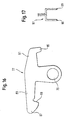
- the rifle only partially shown is a Caribbeanladeflinte, which may be provided with a box magazine ( Fig. 1, 2 ).
- the shotgun has a traveler 1 with a center axis bez. Soul Axis 37 up.
- a cartridge chamber 3 is formed, to which an end portion 4 of the traveler 1 connects to the rear.
- the end portion 4 has an approximately U-shaped, downwardly open cross section ( Fig. 4 ) and has a central, upper locking recess 5 and below two locking notches 6. The latter sit in the free ends of the two legs of the U-section.
- a parallel to the axis of the soul 37 extending groove 10 is provided, in each of which a cartridge extractor 61 (FIG. Fig. 6 ) can run.
- the cartridge chamber 3 is closed at shot ready weapon by a closure head 11 to the rear. This is penetrated by a front vertical transverse bore, which in turn receives a locking block 25.
- This locking block has a reverse T-shaped cross section transverse to the axis of the soul ( Fig. 5 ); with a conical locking projection 7 at the free (upper) end of the central shaft and a respective locking finger 8 at each of the two ends of the (lower) cross shaft.
- the locking projection 7 engage in the locking recess 5 and at the same time the locking fingers 8 in the locking notches 6 a.
- All engagement surfaces are at an angle to the vertical, to allow for easy establishment and release of the engagement of the locking block 25 in the end portion 4 of the traveler 1.
- the oblique angle of the surfaces are so low that the engagement is self-locking, so can not be opened by a force on the closure head 11 along the axis of the shaft 37 to the rear.
- Traveler 1 and closure head 11 are thus directly connected to each other during the shot and transmit the high initial forces directly to each other.
- the power transmission does not affect any other element.
- the traveler 1 can therefore be inserted with its rear end in a plastic housing 2. Namely, the largest occurring forces are not introduced into the housing 2.
- the closure head 11 is seated on a closure carrier 13 (FIG. Fig. 3.1 and 3.2 ). This is longitudinally movable relative to the closure head 11 by a certain distance.
- the closure carrier 13 has a longitudinal recess 54, in the area below of the locking block 25 has a transverse recess 53, and behind this a flat surface 59.
- transverse recess 53 is bounded on either side of the longitudinal recess 54 by a respective nose 55 which projects upwards and rearwards and projects beyond the flat surface 59.
- the locking block 25 is formed so that in its upper locking position, the lower surface of its cross-shaft is approximately flush with the lower surface of the closure head 11 ( Fig. 1 ). In this position, the shutter carrier 13 can move under the locking block 25 back and forth, and thereby the shutter head 11 and the locking block 25 on the flat surface 59 of the shutter carrier 13 can slide.
- the unlocked closure head, 11 runs in its further backward movement in a guide (not shown) in the housing 2, that the locking block 25 can not move upwards.
- a rotatable disassembly block 27 is disposed behind the locking block 25 and approximately parallel to the central shaft thereof, which is held by a latch 28 in its position of use ( Fig. 1, 2 . 6 and 8, 9 ).
- the Zerlegeblock 27 is received in a rear, vertical transverse bore 23 in the closure head 11.
- the catch 28 can be triggered by the bore 24 in the closure head 11 ( Fig. 6 ).
- the closure block 25 and the Zerlegeblock 27 are penetrated by a firing pin 19 and each have a respective bore 31 and 34 on.
- the lower end of the Zerlegeblockes 27 is designed as a hammer base 51, which runs in an upwardly open groove 49 with inverted T-shaped cross-section in the closure carrier 13.
- the hammer base 51 engages on both sides of the flanks of the groove 49 and the Zerlegeblock 27 is held by its catch 28, runs a paragraph 35 of the firing pin 19 against an underlying projection 36 in the bore of the Zerlegeblocks 27th on. This prevents that the firing pin 19 can fall back out of the closure head 11 in the position of use. If the Zerlegeblock 27 twisted after overcoming the catch 28 by about an eighth of a turn, then the firing pin 19 can be removed to the rear.
- the penetrated by the firing pin 19 bore 31 in the locking block 25 is formed as a slot, which allows the locking block 25, despite the presence of the firing pin 19, the positions of Fig. 1 and 2 (locked and unlocked).
- the firing pin 19 has behind the slot 31 a thickening 29, while in the back of the slot 31 below a complementary thickening 29 beveled recess 33 is formed.
- the recess 33 and the firing pin thickening 29 are designed so that the firing pin 19 can only plunge into the slot 31 when the locking block 25 is in its uppermost position (locking position of the Fig. 1 ) is located. In this position, the firing pin 19 so deep dive into the slot 31 that its tip for igniting a cartridge from the front surface of the closure head 11 can emerge.
- the recess 33 pushes back the firing pin thickening 29 due to its special shape so far that the firing pin tip can no longer reach a cartridge. This ensures that a cartridge can only be fired when the closure head 11 is sufficiently locked.
- thickening 29 and paragraph 35 hold the firing pin 19 loose between two end positions; the chamfered recess 33 of the locking block forces retraction of the striker when unlocking.
- a firing pin spring is therefore usually superfluous and therefore does not need to be provided.
- the closure carrier 13 could now be a handle, such as a sliding forend, be attached.
- a releasable lock could set this handle in the forefront.
- the closing spring 9 is of course not required, but the handle and thus the shutter carrier would be moved back and forth to load the weapon.
- the closure head 11 is extended to the rear by a central extension tube 15 which receives the - also here - extended firing pin 19 and leads.
- the rear end of the shutter carrier 13 is extended upward to form an abutment 43.
- an intermediate piece 39 is suspended from above in this way in the closure carrier 13, that it is held forward by a step 40 in the closure carrier 13, but is displaceable to the rear.
- Abutment 43 and spacer 39 each have a through hole, both of which are aligned with each other and are penetrated by the extension tube 15.
- the extension tube 15 serves as a holder for a strong compression spring or opening spring 17, which is preferably designed as a helically bent wire spring and surrounds the extension tube.
- the compression spring 17 is supported in the relaxed state at the rear and front on the abutment 43 and on the intermediate piece 39 (until the intermediate piece 39 is seated on the step 40 of the closure carrier 13).
- the strong opening spring 17 is largely ineffective. It only comes into effect when in the locked position of Fig. 1 the closure head 11 moves relative to the closure carrier 13 to the rear.
- the elastomer buffers 41 are preferably composed of a plurality of ring elements and are preferably made of a high hysteresis material. If a weak cartridge is fired, then the elastomeric buffers 41 are not or hardly compressed. But if a very strong cartridge is fired, then the two elastomeric buffers 41 are highly compressed, returning less energy as they re-expand than they previously absorbed. The increased recoil energy of strong cartridges is thus at least partially destroyed - more accurately converted into other forms of energy. hereby is the Verschluß- able to shoot cartridges with very varying recoil energy and thus muzzle energy without about another locking spring 17 would have to be used or malfunction occur. A separate stop between the closure head 11 and closure carrier 13 is missing. Only the arrangement of opening springs 17 and elastomer buffer (s) 41 serves as a stop.
- a further advantage of the closure 11, 13 shown is that in its unlocked state ( Fig. 2 ) the front surface of its closure carrier 13 protrudes slightly beyond the front surface of the closure head 11. Thus, a cartridge can be conveyed upwards without being caught with its bottom on a cartridge extractor or on any protrusion of the front surface of the closure head 11. The thus not loaded closure head 11 also has no desire to lock "on the go”.
- the closure head 11 in this embodiment unusually two opposing cartridge extractor 61.
- a cartridge extractor 61 is in Fig. 7 shown enlarged further. As can be seen, it has a hook-like design with a rearwardly facing hook surface 63, which is intended to sit on the edge of a shotgun from the front. This edge is curved forward and outward, so that the hook surface 63 is seated on a curved training.
- the cartridge ejector (not shown) is located on the right or left, the cartridge case is ejected to the left or to the right. It is essential, however, that no eccentric longitudinal force or transverse force which could originate from a single cartridge extractor 61 acts on the cartridge case when pulling out. This ensures the perfect removal of even very long cartridge cases. Only near the end of the return path of the lock acts an off-center force on the cartridge case, which causes their release first from one and then from the other cartridge extractor 61.
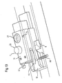
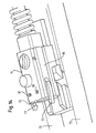
- a repeating rifle is in Fig. 9-12 shown.
- the previous ones Fig. 4 . 5.1, 5.2 . 7 . 8 and 9 also apply to this version.
- the repeating shotgun shown only partially can be provided with a box magazine ( 10, 11 ).
- the shotgun has a traveler 1 with a central axis or axis of the soul 37.
- a cartridge chamber 3 is formed, to which an end portion 4 of the traveler 1 connects to the rear.
- the end portion 4 has an approximately U-shaped, downwardly open cross-section and has a central, upper locking recess 5 and below two locking notches 6. The latter sit in the free ends of the two legs of the U-section.
- a parallel to the axis of the soul 37 extending groove 10 is provided, in each of which a cartridge extractor 61 (FIG. Fig. 13 ) can run.
- the cartridge chamber 3 is closed at shot ready weapon by a closure head 11 to the rear. This is penetrated by a front vertical transverse bore, which in turn receives a locking block 25.
- This locking block has, as already described above, transversely to the axis of the soul on a reverse T-shaped cross-section; with a conical locking projection 7 at the free (upper) end of the central shaft and a respective locking finger 8 at each of the two ends of the (lower) cross shaft.
- the locking projection 7 engage in the locking recess 5 and at the same time the locking fingers 8 in the locking notches 6 a.
- All engagement surfaces are at an angle to the vertical, to allow for easy establishment and release of the engagement of the locking block 25 in the end portion 4 of the traveler 1.
- the oblique angle of the surfaces are so low that the engagement is self-locking, so can not be opened by a force on the closure head 11 along the axis of the shaft 37 to the rear.
- Traveler 1 and closure head 11 are thus directly connected to each other during the shot and transmit the high initial forces directly to each other.
- the power transmission does not affect any other element.
- the traveler 1 can therefore be inserted with its rear end in a plastic housing 2. Namely, the largest occurring forces are not introduced into the housing 2.
- the closure head 11 is seated on a closure carrier 13 (FIG. Fig. 12.1 and 12.2 ). This is longitudinally movable relative to the closure head 11 by a certain distance.
- the closure carrier 13 has a longitudinal recess 54, in the region below the locking block 25 has a transverse recess 53, and behind this a flat surface 59th
- transverse recess 53 is bounded on either side of the longitudinal recess 54 by a respective nose 55 which projects upwards and rearwards and projects beyond the flat surface 59.
- the locking block 25 is formed so that in its upper locking position, the lower surface of its transverse shaft approximately flush with the lower surface of the closure head 11 completes ( Fig. 10 ). In this position, the shutter carrier 13 can move under the locking block 25 back and forth, and thereby the shutter head 11 and the locking block 25 on the flat surface 59 of the shutter carrier 13 can slide.
- the unlocked closure head 11 runs in its further backward movement in a guide (not shown) in the housing 2, that the locking block 25 can not move upwards.
- a rotatable disassembly block 27 is disposed behind the locking block 25 and approximately parallel to the central shaft thereof, which is held by a latch 28 in its position of use ( 10, 11 . 13 and 8, 9 ).
- the Zerlegeblock 27 is in a rear, vertical transverse bore 23 received in the closure head 11.
- the closure block 25 and the Zerlegeblock 27 are penetrated by a firing pin 19 and each have a respective bore 31 and 34 on.
- the lower end of the Zerlegeblockes 27 is designed as a hammer base 51, which runs in the longitudinal recess 54 with inverted T-shaped cross section in the closure carrier 13.
- a paragraph 35 of the firing pin 19 runs against an underlying projection 36 in the bore of the Zerlegeblocks 27. This prevents that the firing pin 19 can fall back out of the closure head 11 in the position of use. If the Zerlegeblock 27 twisted after overcoming the catch 28 by about an eighth of a turn, then the firing pin 19 can be removed to the rear.
- the penetrated by the firing pin 19 bore 31 in the locking block 25 is formed as a slot, which allows the locking block 25, despite the presence of the firing pin 19, the positions of Fig. 1 and 2 (locked and unlocked).
- the firing pin 19 has behind the slot 31 a thickening 29, while in the back of the slot 31 below a thickening 29 complementary beveled recess 33 is formed.
- the recess 33 and the firing pin thickening 29 are designed so that the firing pin 19 can only plunge into the slot 31 when the locking block 25 is in its uppermost position (locking position of the Fig. 10 ) is located. In this position, the firing pin 19 so deep dive into the slot 31 that its tip for igniting a cartridge from the front surface of the closure head 11 can emerge.
- the recess 33 pushes back the firing pin thickening 29 due to its special shape so far that the firing pin tip can no longer reach a cartridge. This ensures that a cartridge can only be fired when the closure head 11 is sufficiently locked.
- thickening 29 and paragraph 35 hold the firing pin 19 loose between two end positions; the chamfered recess 33 of the locking block forces retraction of the striker when unlocking.
- a firing pin spring is therefore usually superfluous and therefore does not need to be provided.
- a handle 65 is attached, which is connected for about a displaceable forearm.
- a releasable lock could set this handle in the forefront. The handle and thus the shutter carrier are moved back and forth to load the weapon.
- closure 11, 13 shown An advantage of the closure 11, 13 shown is that in its unlocked state ( Fig. 11 ) the front surface of its closure carrier 13 protrudes slightly beyond the front surface of the closure head 11. Thus, a cartridge can be conveyed upwards without being caught with its bottom on a cartridge extractor or on any protrusion of the front surface of the closure head 11. The thus not loaded closure head 11 also has no desire to lock "on the go”.
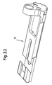
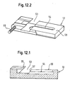
- Fig. 14 shows a closure head 71 which is movable along two guide rods 73.
- This closure has a shock bottom 75, on both sides of which an extractor claw 77 is attached.
- the extractor claw 77 is in Fig. 16 shown enlarged. It is for example stamped from sheet metal and has a total of approximately T-shaped contour, the central shaft has a bore 79 at the end. Transverse from the central shaft at the other end extend a rear leg 81 and a front leg 83.
- the rear leg 81 carries at its free end an angled stub 85, the intended for engagement in a spiral compression spring (not shown).
- the front leg 83 carries at its free end the actual claw 87, which has a center shaft facing 89 surface which extends at an acute angle to the extension of the central shaft, and thus at an acute angle to the shock bottom 75 (FIG. Fig. 15 ).
- the two extractor claws 77 are each pivotable about an axis, approximately in the form of a retaining pin 91, which passes through the bore 79 in each case.
- the closure 1 has on both sides of a longitudinal web 95, on the outside of the corresponding extractor claw 77 is attached.
- Each longitudinal ridge 95 has an upper and a lower edge, which extend into the shock bottom 75 inside.
- Fig. 15 is the closure of Fig. 14 shown in plan view.
- the two claws 77 sit on both sides of a cartridge 93.
- Behind the shutter 71 in the region of its return sits an ejector 97.
- This ejector is shown broken off and seen from above. Seen from the front or rear, the ejector 97 has a U-shaped cross-section.
- the shutter 71 runs back, then the one of the longitudinal webs 95 passes through the ejector 97.
- the two U-legs of this ejector 97 over and under reach the corresponding longitudinal web 95 and reach with their ends to the shock bottom 75. The ends of these legs are in Fig. 17 denoted by 99.
- the cartridge or cartridge case 93 Since the cartridge or cartridge case 93 is held by the extractor claws 77 on the shutter 71 and taken with this, it runs back with the shutter 71.
- the ejector 97 remains stationary during this closure movement. Thus, the longitudinal web 95 moves through the two legs of the Au Collectorers 97 to the rear.
- the shock bottom 75 arrives at the ejector 97, the bottom of the cartridge 93 rests on its ends 99 and is pressed against the local (right) extractor claw 77. Because of the interaction of the round contour of the cartridge edge with the inclined surface 89 (FIG. Fig. 16 ), the extractor claw 77 is pushed back, and the ejector 97 gives the right part of the cartridge edge a strong impact, so that the cartridge 93 tilts around the left extractor 77 and is ejected.
- the ejector 97 can be inserted into a longitudinal or transverse groove in the weapon housing. A component of the weapon or a pin can hold the ejector in this position.
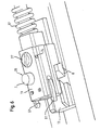
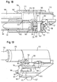
- the parts shown belong to a large-caliber self-loading rifle for garnet cartridges, the total length is about 90 mm, the sleeve length but less than 30 mm.
- the caliber is 20 mm. All figures show the same embodiment; the reference numbers apply to all figures.
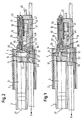
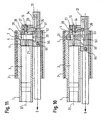
- the rifle has a barrel 101 which is inserted into a force introduction part 104.
- the rear end of the barrel 101 is designed as a cartridge chamber 103.
- cartridge chamber In cartridge chamber, the cartridge case 165 of a cartridge 163 is added.
- the force introduction part 104 forms a central anchoring element to which not only the barrel 101, but also a housing, a target electronics, a belt carrier and an attachment (grenade launcher, automatic rifle, etc.) can be attached.
- the force introduction part 104 is above the receiving bore for the barrel 101 and parallel to this of a bore permeated, whose front part has a smaller diameter than bore 167 is formed for the closing spring tube 169 and opens into a larger bore, which forms a gas cylinder 171.
- the transition between the two holes 167, 171 is chamfered. This transition is connected to the barrel 101 through a gas removal hole 173 which extends transversely to this and opens into this at the end of the cartridge chamber 103.
- a one-piece tube which is composed of two cylindrical pipe sections with different diameter: a closing spring tube 169 and a gas piston 175.
- the closing spring tube 169 is slidably, but substantially sealing in the bore 167th die
- Gaskolben 175 sits slidably, but substantially sealing in the gas cylinder 171.
- the shoulder between the two pipe sections 169 and 175 forms the active surface of the gas piston 175.
- the gas piston 175 is extended in one piece to the rear by a closure carrier 113.
- the movable member from the tube 169, the gas piston 175 and the shutter carrier 113 is penetrated by a hole open to the rear. The front of the hole is closed.
- a closing spring-receiving bore sits a closing spring, not shown, which is supported behind the arrangement shown in the closure.
- At the front of the closing spring tube 169 (not shown here) engages a loading lever, by means of which the entire component 169, 175, 113 is pushed back, against the force of the closing spring.
- the closure carrier is moved back either by hand or automatically. He puts it back a linear trajectory, which runs parallel to the central axis of the barrel. Not shown longitudinal grooves in the housing thereby lead the closure carrier, together with the guide of the closing spring tube 169 in the bore 167 and the gas piston 175 in the gas cylinder 171 each in the force introduction part 104th
- a closure head 111 Behind the barrel 101 and thus under the closure carrier 113 there is a closure head 111. This is movable together with the closure carrier 113 to the rear and front, but not alone. The movement distance is longer than the length of a cartridge 163. Also, the movement of the closure head 111 is guided by not shown longitudinal grooves or webs in the housing.
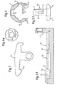
- the closure head 111 is penetrated by a locking bolt 125 which has the shape of a vertical letter "T", the vertical bar.
- a vertical bore 121 in the closure head 111 passes through.
- This vertical beam terminates at the bottom in a latch extension 107.
- a transverse horizontal bar of the "T” terminates on both sides in a respective latching finger 108. In the center, the horizontal bar has a rearwardly extending coupling projection 183.
- FIG. 20 shows three abutments are formed in the force introduction part 104 for the locking pin 125, namely, a lower, a conical bore-forming locking recess 105 whose center lies on a vertical, which passes through the barrel center axis, and two locking notches 106 symmetrical to this vertical.
- the locking notches 106 are located in front of protrusions of the inner surface of the force introduction part 104.
- the locking pin 125 When the locking pin 125 is in the lower position shown, the locking position, it engages with the locking projection 107 in the locking recess 105, and the locking fingers 108 engage in the locking notches 106 a. The closure head 111 is then firmly locked in the force introduction part 104. This is the locking position of the locking bolt 125th
- the locking pin 125 When the locking pin 125 is raised, the locking projection 107 is released upwardly from the locking recess, and the locking fingers 108 are exposed upward from the locking notches 106. Now, the shutter head 111 is unlocked and can move to the rear. This is the unlocking position of the locking bolt 125.
- a firing pin 119 passes horizontally and centrally, relative to the barrel 101, the locking pin 125th
- the firing pin 119 passes through a slot 131 in the locking bolt 125, so that it can move freely between the locking position and the unlocking position.
- the firing pin 119 has, as in Fig. 21 to see in the back of a paragraph or a thickening 129 on.
- the back of the elongated hole 131 is provided with a bevel 133 extending obliquely upwards and forwards from below and behind. This chamfer allows the firing pin 119 in the locking bolt 125 from behind dive when they are in the locking position shown.
- the bevel 133 pushes the thickening 129 of the firing pin 119 and thus this backwards.
- the firing pin can thus reach its foremost position only when the locking pin 125 is in its locking position, so that ignition of a cartridge 163 can take place only in this position.
- a spring, which is required in other weapons for pushing back the firing pin 119 is here replaced by the positive control, which is realized by the bevel 133.
- a transverse shaft 189 is further arranged behind the locking bolt 125, rotatably mounted on a central rocker arm 187.
- One leg of this rocker arm 187 engages under the coupling projection 183, the other leg is up to below the shutter carrier 113th
- a downwardly projecting locking projection 185 is formed on the closure carrier 113, the front side of which has a bevel 193 extending upwards and forwards.
- the locking projection 185 when the shutter carrier 113 is moved by hand or by gas pressure to the rear, the locking projection 185 also runs backwards and releases the locking pin 125. At the same time, the locking projection 185 runs against the vertical leg of the rocker arm 187 and pivots it in the sequence (in the drawing in a clockwise direction). In this case, the horizontal leg of the rocker arm 187 lifts the coupling projection 183 and thus also the locking pin 125. Whose upper part now falls into a coupling groove 191, which is formed on the underside of the closure carrier 113 in front of the bevel 193.
- the locking projection 185 runs on the upper leg of the rocker arm 187 and holds it tilted so that it holds the locking pin 125 in the upper position in which it engages in the groove 191.
- the locking pin 125 and thus the locking head 111 forcibly follow the movement of the shutter carrier 113 to the rear. In this case engages under a housing (not shown) housing the locking bolt 125 from below and prevents it can fall down. The described connection between the parts thus remains maintained.
- the weapon is now ready to fire when a cartridge 163 is in the chamber 103.
- the length of the cartridge case 165 is less than one third of the total return of the closure 111, 113. This means that the cartridge case 165 is already fully extended from the cartridge chamber 103 even before the closure 111, 113 is significantly slowed down by the closing spring becomes. However, the acceleration phase of the shutter 111, 113 is already completed, since the barrel 101 must be virtually depressurized when the cartridge case 165 is fully extended.
- the impact bottom 181 of the closure head 111 is provided with an edge ridge 195 at the top and bottom. It is more difficult to ensure the lateral support of the cartridge case 165.
- FIG. 21 shows a horizontal section through the center of the closure head 111.
- the closure head 111 has on both sides and symmetrically to each other two slot-shaped recesses 110, which terminates at the rear by a spring bore 197.
- an extractor claw 161 is used, on which a (not shown) spring in the associated spring bore 197 acts via a plunger.
- the extractor claw 161 is pivotable about a vertical axis.
- a support body 199 In the other recess 110 sits a support body 199, which is also held by a vertical axis.
- This support body 199 is generally similar to the extractor claw 161, but is a little larger so that it can not move in the recess 110.
- the support body 199 unlike the Ausieher claw 161, does not surround the cartridge bottom of a cartridge chamber 104 located in cartridge chamber 104.
Landscapes
- Engineering & Computer Science (AREA)
- General Engineering & Computer Science (AREA)
- Toys (AREA)
- Portable Nailing Machines And Staplers (AREA)
- Emergency Lowering Means (AREA)
- Ladders (AREA)
- Organic Low-Molecular-Weight Compounds And Preparation Thereof (AREA)
- Aiming, Guidance, Guns With A Light Source, Armor, Camouflage, And Targets (AREA)
- Non-Flushing Toilets (AREA)
- Seal Device For Vehicle (AREA)
- Medical Preparation Storing Or Oral Administration Devices (AREA)
- Medicines Containing Plant Substances (AREA)
Claims (10)
- Fusil de gros calibre, comportant un élément d'introduction de force (104) central qui reçoit l'extrémité arrière d'un canon (101) et les butées (105, 106) à verrouiller d'une culasse (111, 113),■ le canon (101) comportant encore un orifice d'emprunt de gaz (173) dans l'élément d'introduction de force (104),■ un cylindre à gaz (171) étant relié de manière fixe à l'élément d'introduction de force (104), qui est relié à l'orifice d'emprunt de gaz (173) ;
caractérisé en ce qu'il comporte une tête de culasse (111) et un support de culasse (113),■ le support de culasse (113) formant le piston à gaz (175),■ un boulon de verrouillage (125) traversant transversalement la tête de culasse (111) et étant poussé par le support de culasse (113), dans sa position de repos, dans une position de verrouillage, dans laquelle ledit boulon s'engage dans des creux (105, 106) de l'élément d'introduction de force (104) et, de ce fait, verrouille la tête de culasse (111),■ le boulon de verrouillage (125) comportant un trou oblong (131), à travers lequel passe le percuteur (119),■ le percuteur (119) comportant un épaulement (129) en aval du boulon de verrouillage (125), et■ le trou oblong (131) comportant vers l'arrière un chanfrein (133), qui entre en contact avec l'épaulement (129) du percuteur (119) et pousse celui-ci vers l'arrière, lorsque le boulon de verrouillage (125) est tiré hors de sa prise avec les creux (105, 106) de l'élément d'introduction de force (104). - Fusil selon la revendication 1, dans lequel le canon (101) est muni d'une chambre de cartouche (103), caractérisé en ce que l'orifice d'emprunt de gaz (173) est situé à proximité de l'extrémité supérieure de la chambre de cartouche et débouche dans une forure (173) dans l'élément d'introduction de force (104), laquelle débouche dans l'extrémité avant du cylindre à gaz (171).
- Fusil selon la revendication 2, caractérisé en ce que le cylindre à gaz (171) est réalisé dans l'élément d'introduction de force (104) lui-même.
- Fusil selon la revendication 2, caractérisé en ce que la forure (173) s'étend transversalement à la direction de tir.
- Fusil selon l'une quelconque des revendications 2 à 4, caractérisé en ce que le cylindre à gaz (171) est logé au-dessus de la chambre de cartouche (104).
- Fusil selon l'une quelconque des revendications 1 à 5, caractérisé en ce qu'un tube (169) est relié de manière fixe ou d'un seul tenant au support de culasse (113), traverse partiellement le cylindre à gaz (171) et, en tant que tube de réception pour un ressort de verrouillage, est traversé par celui-ci.
- Fusil selon la revendication 6, caractérisé en ce qu'un dispositif de manoeuvre de la charge est relié ou peut être relié au tube (169).
- Fusil selon l'une quelconque des revendications 1 à 7, caractérisé en ce qu'un levier basculant (187) est disposé dans la tête de culasse (111), s'engage, d'une part, dans la trajectoire de mouvement du support de culasse (113) et, d'autre part, dans la trajectoire de mouvement du boulon de verrouillage (125) et, pendant un mouvement du support de culasse (113) hors de sa position de repos, tire le boulon de verrouillage (125) hors des creux (105, 106) de l'élément d'introduction de force (104).
- Fusil selon la revendication 8, caractérisé en ce que le boulon de verrouillage (125) extrait s'engage dans le support de culasse (113), de telle sorte que le boulon de verrouillage (125) et, avec celui-ci, la tête de culasse (111) sont entraînés conjointement avec le mouvement dudit support de culasse.
- Fusil selon l'une quelconque des revendications 1 à 9, caractérisé en ce que dans la tête de culasse (111) sont réalisés, transversalement au boulon de verrouillage (125), deux évidements (110), dans lesquels sont réalisés depuis l'arrière respectivement une forure (197) pour un boulon de pression et un ressort poussant ce dernier vers l'avant, en ce que, dans l'un des évidements (110) est inséré un extracteur (161), apte à pivoter dans le sens opposé à la force exercée par le boulon de pression, et en ce que dans l'évidement en regard est inséré de manière immobile un élément d'appui (199) qui, en face de l'extracteur (161), constitue un appui latéral pour le fond d'une cartouche (179) ou d'une douille de cartouche (165).
Applications Claiming Priority (3)
| Application Number | Priority Date | Filing Date | Title |
|---|---|---|---|
| DE10240891A DE10240891A1 (de) | 2002-09-04 | 2002-09-04 | Handfeuerwaffe mit verriegeltem Verschluß |
| DE10240891 | 2002-09-04 | ||
| PCT/EP2003/009483 WO2004029534A2 (fr) | 2002-09-04 | 2003-08-27 | Arme a feu de poing a culasse verrouillee |
Publications (2)
| Publication Number | Publication Date |
|---|---|
| EP1535012A2 EP1535012A2 (fr) | 2005-06-01 |
| EP1535012B1 true EP1535012B1 (fr) | 2009-02-11 |
Family
ID=31724340
Family Applications (1)
| Application Number | Title | Priority Date | Filing Date |
|---|---|---|---|
| EP03798134A Expired - Lifetime EP1535012B1 (fr) | 2002-09-04 | 2003-08-27 | Arme a feu de poing a culasse verrouillee |
Country Status (10)
| Country | Link |
|---|---|
| EP (1) | EP1535012B1 (fr) |
| KR (1) | KR100664792B1 (fr) |
| AT (1) | ATE422653T1 (fr) |
| AU (1) | AU2003260463A1 (fr) |
| CA (1) | CA2493602C (fr) |
| DE (2) | DE10240891A1 (fr) |
| ES (1) | ES2321929T3 (fr) |
| PT (1) | PT1535012E (fr) |
| WO (1) | WO2004029534A2 (fr) |
| ZA (1) | ZA200501827B (fr) |
Cited By (2)
| Publication number | Priority date | Publication date | Assignee | Title |
|---|---|---|---|---|
| US8807010B2 (en) | 2011-08-24 | 2014-08-19 | Merkel Jagd-und Sportwaffen GmbH | Pistol with barrel locking device |
| EP3704435A4 (fr) * | 2017-10-10 | 2022-06-15 | Armsan Silah Sanayi Ve Ticaret Anonim Sirketi | Nouvelle structure de mécanisme pour des armes à feu |
Families Citing this family (4)
| Publication number | Priority date | Publication date | Assignee | Title |
|---|---|---|---|---|
| KR101263903B1 (ko) | 2011-03-09 | 2013-05-13 | 류진우 | 분해식 약실이 구비된 소총 |
| KR101263907B1 (ko) | 2011-03-24 | 2013-05-13 | 류진우 | 가스관 내장형 총열이 구비된 소총 |
| IT201800006179A1 (it) * | 2018-06-11 | 2019-12-11 | Gerardo Gabriele Restaino | Meccanismo di chiusura per armi da fuoco portatili con espulsione anteriore del bossolo |
| DE102018114064A1 (de) * | 2018-06-13 | 2019-12-19 | L&O Hunting Group GmbH | Verschluss eines Repetiergewehr und Repetiergewehr mit einem derartigen Verschluss |
Family Cites Families (18)
| Publication number | Priority date | Publication date | Assignee | Title |
|---|---|---|---|---|
| DE374753C (de) * | 1923-04-27 | Felix Delu | Selbstladepistole | |
| US2732768A (en) * | 1956-01-31 | E browning | ||
| US1043670A (en) * | 1910-12-07 | 1912-11-05 | Rheinische Metallw & Maschf | Breech-block mechanism for firearms or guns. |
| FR637155A (fr) * | 1926-10-30 | 1928-04-24 | Perfectionnements aux mécanismes extracteurs pour étuis de cartouches à bourrelet mince | |
| BE398412A (fr) * | 1932-09-03 | |||
| BE413944A (fr) * | 1935-03-15 | |||
| NL59745C (fr) * | 1938-07-13 | |||
| BE467864A (fr) * | 1945-09-21 | |||
| BE473028A (fr) * | 1946-05-04 | |||
| FR1266597A (fr) * | 1960-06-02 | 1961-07-17 | France Etat Armement | Procédé et dispositif d'emprunt de gaz pour armes automatiques |
| US3213558A (en) * | 1964-03-04 | 1965-10-26 | High Standard Mfg Corp | Means for mounting bolt-actuating device for firearms |
| US3776096A (en) * | 1971-10-21 | 1973-12-04 | J Donovan | Gas operated firearm |
| FI48878C (fi) | 1973-01-26 | 1975-01-10 | Valmet Oy | Patruunan hylsyn ulosvetäjä kiertyväsulkuisiin aseisiin. |
| US3791060A (en) * | 1973-03-08 | 1974-02-12 | N Weaver | Convertible bolt action rifle |
| IT1172795B (it) * | 1983-05-09 | 1987-06-18 | Benelli Armi Spa | Chiusura a testina rotante ed otturatore per armi da fuoco automatiche a funzionamento inerziale utilizzante l'energia cinetica del rinculo |
| US4580484A (en) * | 1984-04-13 | 1986-04-08 | Moore Wildey J | Firearm and firearm conversion unit |
| AT393028B (de) * | 1986-04-08 | 1991-07-25 | Maximilian Vojta | Gasentnahmesystem fuer eine feuerwaffe |
| US5983774A (en) * | 1997-03-07 | 1999-11-16 | Mihaita; Ion | Machine gun |
-
2002
- 2002-09-04 DE DE10240891A patent/DE10240891A1/de not_active Withdrawn
-
2003
- 2003-08-27 CA CA002493602A patent/CA2493602C/fr not_active Expired - Fee Related
- 2003-08-27 DE DE50311173T patent/DE50311173D1/de not_active Expired - Fee Related
- 2003-08-27 PT PT03798134T patent/PT1535012E/pt unknown
- 2003-08-27 KR KR1020057003729A patent/KR100664792B1/ko not_active IP Right Cessation
- 2003-08-27 AT AT03798134T patent/ATE422653T1/de not_active IP Right Cessation
- 2003-08-27 ES ES03798134T patent/ES2321929T3/es not_active Expired - Lifetime
- 2003-08-27 AU AU2003260463A patent/AU2003260463A1/en not_active Abandoned
- 2003-08-27 EP EP03798134A patent/EP1535012B1/fr not_active Expired - Lifetime
- 2003-08-27 WO PCT/EP2003/009483 patent/WO2004029534A2/fr not_active Application Discontinuation
-
2005
- 2005-03-03 ZA ZA200501827A patent/ZA200501827B/en unknown
Cited By (2)
| Publication number | Priority date | Publication date | Assignee | Title |
|---|---|---|---|---|
| US8807010B2 (en) | 2011-08-24 | 2014-08-19 | Merkel Jagd-und Sportwaffen GmbH | Pistol with barrel locking device |
| EP3704435A4 (fr) * | 2017-10-10 | 2022-06-15 | Armsan Silah Sanayi Ve Ticaret Anonim Sirketi | Nouvelle structure de mécanisme pour des armes à feu |
Also Published As
| Publication number | Publication date |
|---|---|
| AU2003260463A1 (en) | 2004-04-19 |
| DE50311173D1 (de) | 2009-03-26 |
| ZA200501827B (en) | 2005-09-07 |
| WO2004029534A3 (fr) | 2004-06-03 |
| CA2493602C (fr) | 2008-10-14 |
| WO2004029534A2 (fr) | 2004-04-08 |
| DE10240891A1 (de) | 2004-03-18 |
| EP1535012A2 (fr) | 2005-06-01 |
| CA2493602A1 (fr) | 2004-04-08 |
| KR20050112073A (ko) | 2005-11-29 |
| KR100664792B1 (ko) | 2007-01-04 |
| PT1535012E (pt) | 2009-04-09 |
| ATE422653T1 (de) | 2009-02-15 |
| AU2003260463A8 (en) | 2004-04-19 |
| ES2321929T3 (es) | 2009-06-15 |
Similar Documents
| Publication | Publication Date | Title |
|---|---|---|
| DE4341131C1 (de) | Schußwaffe mit Rückstoßabpufferung, insbesondere Faustfeuerwaffe | |
| EP0505917B1 (fr) | Arme à feu, notamment arme de poing | |
| DE3033842A1 (de) | Gewehr | |
| WO2005108900A1 (fr) | Arme a feu semi-automatique portable comportant un support de verrou de culasse accelere | |
| EP2018508B1 (fr) | Système de fermeture d'une arme | |
| AT412743B (de) | Verschlusssystem für eine feuerwaffe | |
| DE19722806C1 (de) | Selbstladepistole, Umrüstbausatz für verriegelte Selbstladepistole und Waffensystem aus einer wahlweise verriegelten oder unverriegelten Selbstladepistole | |
| EP3488172B1 (fr) | Arme à canon, en particulier pistolet, comprenant un amortisseur de recul | |
| EP3964786A1 (fr) | Carcasse pour une arme à feu à chargement automatique, ainsi que arme à feu à chargement automatique équipée d'une telle carcasse | |
| DE2418049A1 (de) | Feuerwaffe od.dgl. und munition fuer dieselbe | |
| EP1535012B1 (fr) | Arme a feu de poing a culasse verrouillee | |
| DE10253668A1 (de) | Brennkraftbetriebenes Setzgerät | |
| AT524218A4 (de) | Schusswaffe | |
| DE1166052B (de) | Einsatzgeraet mit Einstecklauf zum Verschiessen von Kleinkaliber-Munition durch automatische Handfeuerwaffen, insbesondere Sturmgewehre mit Hammerzuendung | |
| EP1535013A1 (fr) | Arme a chargement automatique verrouillee | |
| EP1535015B1 (fr) | Chargeur a pression de gaz | |
| DE4035860A1 (de) | Automatische handfeuerwaffe mit starr verriegeltem verschluss fuer huelsenlose munition | |
| DE4345591B4 (de) | Selbstlade-Granatwerfer | |
| DE1553854C3 (de) | Verschluß für Handfeuerwaffen | |
| DE3142350A1 (de) | "schusswaffe" | |
| DE102021004902A1 (de) | Schließfedereinrichtung für eine Handfeuerwaffe, Handfeuerwaffe mit einer Schließfedereinrichtung | |
| DE3308993A1 (de) | Kleinbauende automatische handfeuerwaffe mit neuem verschlusssystem | |
| DE1553854B2 (de) | Verschluß für Handfeuerwaffen | |
| DE2207554A1 (de) | Zylinderdrehverschluss fuer jagdwaffen | |
| DE1703417B (de) | Selbstladepistole |
Legal Events
| Date | Code | Title | Description |
|---|---|---|---|
| PUAI | Public reference made under article 153(3) epc to a published international application that has entered the european phase |
Free format text: ORIGINAL CODE: 0009012 |
|
| 17P | Request for examination filed |
Effective date: 20050209 |
|
| AK | Designated contracting states |
Kind code of ref document: A2 Designated state(s): AT BE BG CH CY CZ DE DK EE ES FI FR GB GR HU IE IT LI LU MC NL PT RO SE SI SK TR |
|
| AX | Request for extension of the european patent |
Extension state: AL LT LV MK |
|
| DAX | Request for extension of the european patent (deleted) | ||
| RAP1 | Party data changed (applicant data changed or rights of an application transferred) |
Owner name: HECKLER & KOCH GMBH |
|
| GRAP | Despatch of communication of intention to grant a patent |
Free format text: ORIGINAL CODE: EPIDOSNIGR1 |
|
| GRAS | Grant fee paid |
Free format text: ORIGINAL CODE: EPIDOSNIGR3 |
|
| GRAA | (expected) grant |
Free format text: ORIGINAL CODE: 0009210 |
|
| AK | Designated contracting states |
Kind code of ref document: B1 Designated state(s): AT BE BG CH CY CZ DE DK EE ES FI FR GB GR HU IE IT LI LU MC NL PT RO SE SI SK TR |
|
| REG | Reference to a national code |
Ref country code: GB Ref legal event code: FG4D Free format text: NOT ENGLISH |
|
| REG | Reference to a national code |
Ref country code: CH Ref legal event code: EP |
|
| REG | Reference to a national code |
Ref country code: IE Ref legal event code: FG4D Free format text: LANGUAGE OF EP DOCUMENT: GERMAN |
|
| REG | Reference to a national code |
Ref country code: CH Ref legal event code: NV Representative=s name: E. BLUM & CO. AG PATENT- UND MARKENANWAELTE VSP |
|
| REF | Corresponds to: |
Ref document number: 50311173 Country of ref document: DE Date of ref document: 20090326 Kind code of ref document: P |
|
| REG | Reference to a national code |
Ref country code: PT Ref legal event code: SC4A Free format text: AVAILABILITY OF NATIONAL TRANSLATION Effective date: 20090331 |
|
| REG | Reference to a national code |
Ref country code: GR Ref legal event code: EP Ref document number: 20090401178 Country of ref document: GR |
|
| REG | Reference to a national code |
Ref country code: ES Ref legal event code: FG2A Ref document number: 2321929 Country of ref document: ES Kind code of ref document: T3 |
|
| PG25 | Lapsed in a contracting state [announced via postgrant information from national office to epo] |
Ref country code: FI Free format text: LAPSE BECAUSE OF FAILURE TO SUBMIT A TRANSLATION OF THE DESCRIPTION OR TO PAY THE FEE WITHIN THE PRESCRIBED TIME-LIMIT Effective date: 20090211 Ref country code: SI Free format text: LAPSE BECAUSE OF FAILURE TO SUBMIT A TRANSLATION OF THE DESCRIPTION OR TO PAY THE FEE WITHIN THE PRESCRIBED TIME-LIMIT Effective date: 20090211 |
|
| PG25 | Lapsed in a contracting state [announced via postgrant information from national office to epo] |
Ref country code: SE Free format text: LAPSE BECAUSE OF FAILURE TO SUBMIT A TRANSLATION OF THE DESCRIPTION OR TO PAY THE FEE WITHIN THE PRESCRIBED TIME-LIMIT Effective date: 20090511 |
|
| REG | Reference to a national code |
Ref country code: IE Ref legal event code: FD4D |
|
| PG25 | Lapsed in a contracting state [announced via postgrant information from national office to epo] |
Ref country code: EE Free format text: LAPSE BECAUSE OF FAILURE TO SUBMIT A TRANSLATION OF THE DESCRIPTION OR TO PAY THE FEE WITHIN THE PRESCRIBED TIME-LIMIT Effective date: 20090211 Ref country code: CZ Free format text: LAPSE BECAUSE OF FAILURE TO SUBMIT A TRANSLATION OF THE DESCRIPTION OR TO PAY THE FEE WITHIN THE PRESCRIBED TIME-LIMIT Effective date: 20090211 Ref country code: IE Free format text: LAPSE BECAUSE OF FAILURE TO SUBMIT A TRANSLATION OF THE DESCRIPTION OR TO PAY THE FEE WITHIN THE PRESCRIBED TIME-LIMIT Effective date: 20090211 Ref country code: DK Free format text: LAPSE BECAUSE OF FAILURE TO SUBMIT A TRANSLATION OF THE DESCRIPTION OR TO PAY THE FEE WITHIN THE PRESCRIBED TIME-LIMIT Effective date: 20090211 |
|
| PG25 | Lapsed in a contracting state [announced via postgrant information from national office to epo] |
Ref country code: RO Free format text: LAPSE BECAUSE OF FAILURE TO SUBMIT A TRANSLATION OF THE DESCRIPTION OR TO PAY THE FEE WITHIN THE PRESCRIBED TIME-LIMIT Effective date: 20090211 Ref country code: SK Free format text: LAPSE BECAUSE OF FAILURE TO SUBMIT A TRANSLATION OF THE DESCRIPTION OR TO PAY THE FEE WITHIN THE PRESCRIBED TIME-LIMIT Effective date: 20090211 |
|
| PLBE | No opposition filed within time limit |
Free format text: ORIGINAL CODE: 0009261 |
|
| STAA | Information on the status of an ep patent application or granted ep patent |
Free format text: STATUS: NO OPPOSITION FILED WITHIN TIME LIMIT |
|
| 26N | No opposition filed |
Effective date: 20091112 |
|
| PG25 | Lapsed in a contracting state [announced via postgrant information from national office to epo] |
Ref country code: BG Free format text: LAPSE BECAUSE OF FAILURE TO SUBMIT A TRANSLATION OF THE DESCRIPTION OR TO PAY THE FEE WITHIN THE PRESCRIBED TIME-LIMIT Effective date: 20090511 |
|
| BERE | Be: lapsed |
Owner name: HECKLER & KOCH G.M.B.H. Effective date: 20090831 |
|
| PG25 | Lapsed in a contracting state [announced via postgrant information from national office to epo] |
Ref country code: MC Free format text: LAPSE BECAUSE OF NON-PAYMENT OF DUE FEES Effective date: 20090831 |
|
| REG | Reference to a national code |
Ref country code: NL Ref legal event code: V1 Effective date: 20100301 Ref country code: CH Ref legal event code: PL |
|
| GBPC | Gb: european patent ceased through non-payment of renewal fee |
Effective date: 20090827 |
|
| PG25 | Lapsed in a contracting state [announced via postgrant information from national office to epo] |
Ref country code: CH Free format text: LAPSE BECAUSE OF NON-PAYMENT OF DUE FEES Effective date: 20090831 Ref country code: LI Free format text: LAPSE BECAUSE OF NON-PAYMENT OF DUE FEES Effective date: 20090831 |
|
| REG | Reference to a national code |
Ref country code: FR Ref legal event code: ST Effective date: 20100430 |
|
| REG | Reference to a national code |
Ref country code: PT Ref legal event code: MM4A Free format text: LAPSE DUE TO NON-PAYMENT OF FEES Effective date: 20100527 |
|
| PG25 | Lapsed in a contracting state [announced via postgrant information from national office to epo] |
Ref country code: BE Free format text: LAPSE BECAUSE OF NON-PAYMENT OF DUE FEES Effective date: 20090831 |
|
| PG25 | Lapsed in a contracting state [announced via postgrant information from national office to epo] |
Ref country code: FR Free format text: LAPSE BECAUSE OF NON-PAYMENT OF DUE FEES Effective date: 20090831 Ref country code: DE Free format text: LAPSE BECAUSE OF NON-PAYMENT OF DUE FEES Effective date: 20100302 Ref country code: NL Free format text: LAPSE BECAUSE OF NON-PAYMENT OF DUE FEES Effective date: 20100301 Ref country code: PT Free format text: LAPSE BECAUSE OF NON-PAYMENT OF DUE FEES Effective date: 20100527 |
|
| REG | Reference to a national code |
Ref country code: ES Ref legal event code: FD2A Effective date: 20090828 |
|
| PG25 | Lapsed in a contracting state [announced via postgrant information from national office to epo] |
Ref country code: GR Free format text: LAPSE BECAUSE OF NON-PAYMENT OF DUE FEES Effective date: 20100303 |
|
| PG25 | Lapsed in a contracting state [announced via postgrant information from national office to epo] |
Ref country code: GB Free format text: LAPSE BECAUSE OF NON-PAYMENT OF DUE FEES Effective date: 20090827 Ref country code: AT Free format text: LAPSE BECAUSE OF NON-PAYMENT OF DUE FEES Effective date: 20090827 |
|
| PG25 | Lapsed in a contracting state [announced via postgrant information from national office to epo] |
Ref country code: IT Free format text: LAPSE BECAUSE OF NON-PAYMENT OF DUE FEES Effective date: 20090827 |
|
| PG25 | Lapsed in a contracting state [announced via postgrant information from national office to epo] |
Ref country code: LU Free format text: LAPSE BECAUSE OF NON-PAYMENT OF DUE FEES Effective date: 20090827 |
|
| PG25 | Lapsed in a contracting state [announced via postgrant information from national office to epo] |
Ref country code: HU Free format text: LAPSE BECAUSE OF FAILURE TO SUBMIT A TRANSLATION OF THE DESCRIPTION OR TO PAY THE FEE WITHIN THE PRESCRIBED TIME-LIMIT Effective date: 20090812 |
|
| PG25 | Lapsed in a contracting state [announced via postgrant information from national office to epo] |
Ref country code: TR Free format text: LAPSE BECAUSE OF FAILURE TO SUBMIT A TRANSLATION OF THE DESCRIPTION OR TO PAY THE FEE WITHIN THE PRESCRIBED TIME-LIMIT Effective date: 20090211 |
|
| PG25 | Lapsed in a contracting state [announced via postgrant information from national office to epo] |
Ref country code: CY Free format text: LAPSE BECAUSE OF FAILURE TO SUBMIT A TRANSLATION OF THE DESCRIPTION OR TO PAY THE FEE WITHIN THE PRESCRIBED TIME-LIMIT Effective date: 20090211 |
|
| PG25 | Lapsed in a contracting state [announced via postgrant information from national office to epo] |
Ref country code: ES Free format text: LAPSE BECAUSE OF NON-PAYMENT OF DUE FEES Effective date: 20090828 |