EP1533990B1 - Einkupplungsverfahren für eine Übertragerrolle zum Verringern von Laufstörungen - Google Patents
Einkupplungsverfahren für eine Übertragerrolle zum Verringern von Laufstörungen Download PDFInfo
- Publication number
- EP1533990B1 EP1533990B1 EP04027783A EP04027783A EP1533990B1 EP 1533990 B1 EP1533990 B1 EP 1533990B1 EP 04027783 A EP04027783 A EP 04027783A EP 04027783 A EP04027783 A EP 04027783A EP 1533990 B1 EP1533990 B1 EP 1533990B1
- Authority
- EP
- European Patent Office
- Prior art keywords
- transfer roll
- imaging drum
- nip
- media
- velocity
- Prior art date
- Legal status (The legal status is an assumption and is not a legal conclusion. Google has not performed a legal analysis and makes no representation as to the accuracy of the status listed.)
- Expired - Lifetime
Links
- 238000012546 transfer Methods 0.000 title claims description 143
- 238000000034 method Methods 0.000 title claims description 30
- 230000033001 locomotion Effects 0.000 title description 11
- 238000003384 imaging method Methods 0.000 claims description 103
- 230000003213 activating effect Effects 0.000 claims 4
- 230000003247 decreasing effect Effects 0.000 claims 1
- 239000000758 substrate Substances 0.000 description 27
- 239000007788 liquid Substances 0.000 description 13
- 239000011295 pitch Substances 0.000 description 11
- 230000008569 process Effects 0.000 description 9
- 108091008695 photoreceptors Proteins 0.000 description 5
- 230000005540 biological transmission Effects 0.000 description 4
- 230000008859 change Effects 0.000 description 3
- 238000001816 cooling Methods 0.000 description 3
- 230000001419 dependent effect Effects 0.000 description 3
- 238000010586 diagram Methods 0.000 description 3
- 230000002093 peripheral effect Effects 0.000 description 3
- 239000007787 solid Substances 0.000 description 3
- 229910000831 Steel Inorganic materials 0.000 description 2
- 230000015556 catabolic process Effects 0.000 description 2
- 238000004590 computer program Methods 0.000 description 2
- 229920001971 elastomer Polymers 0.000 description 2
- 239000000806 elastomer Substances 0.000 description 2
- 230000006870 function Effects 0.000 description 2
- 238000010438 heat treatment Methods 0.000 description 2
- 238000007641 inkjet printing Methods 0.000 description 2
- 238000007639 printing Methods 0.000 description 2
- 230000004044 response Effects 0.000 description 2
- 238000000926 separation method Methods 0.000 description 2
- 239000010959 steel Substances 0.000 description 2
- 230000001052 transient effect Effects 0.000 description 2
- 230000009471 action Effects 0.000 description 1
- XAGFODPZIPBFFR-UHFFFAOYSA-N aluminium Chemical compound [Al] XAGFODPZIPBFFR-UHFFFAOYSA-N 0.000 description 1
- 229910052782 aluminium Inorganic materials 0.000 description 1
- 238000013459 approach Methods 0.000 description 1
- 239000003795 chemical substances by application Substances 0.000 description 1
- 239000011248 coating agent Substances 0.000 description 1
- 238000000576 coating method Methods 0.000 description 1
- 230000007547 defect Effects 0.000 description 1
- 238000006731 degradation reaction Methods 0.000 description 1
- 230000003111 delayed effect Effects 0.000 description 1
- 238000010017 direct printing Methods 0.000 description 1
- 230000000694 effects Effects 0.000 description 1
- 238000002474 experimental method Methods 0.000 description 1
- 239000012943 hotmelt Substances 0.000 description 1
- 238000009413 insulation Methods 0.000 description 1
- 230000007246 mechanism Effects 0.000 description 1
- 238000002844 melting Methods 0.000 description 1
- 230000008018 melting Effects 0.000 description 1
- 238000012986 modification Methods 0.000 description 1
- 230000004048 modification Effects 0.000 description 1
- 238000007645 offset printing Methods 0.000 description 1
- 230000003287 optical effect Effects 0.000 description 1
- 230000009467 reduction Effects 0.000 description 1
- 239000004065 semiconductor Substances 0.000 description 1
- 239000000126 substance Substances 0.000 description 1
Images



Classifications
-
- H—ELECTRICITY
- H04—ELECTRIC COMMUNICATION TECHNIQUE
- H04N—PICTORIAL COMMUNICATION, e.g. TELEVISION
- H04N1/00—Scanning, transmission or reproduction of documents or the like, e.g. facsimile transmission; Details thereof
- H04N1/00681—Detecting the presence, position or size of a sheet or correcting its position before scanning
- H04N1/00742—Detection methods
- H04N1/00745—Detecting the leading or trailing ends of a moving sheet
-
- B—PERFORMING OPERATIONS; TRANSPORTING
- B41—PRINTING; LINING MACHINES; TYPEWRITERS; STAMPS
- B41J—TYPEWRITERS; SELECTIVE PRINTING MECHANISMS, i.e. MECHANISMS PRINTING OTHERWISE THAN FROM A FORME; CORRECTION OF TYPOGRAPHICAL ERRORS
- B41J2/00—Typewriters or selective printing mechanisms characterised by the printing or marking process for which they are designed
- B41J2/005—Typewriters or selective printing mechanisms characterised by the printing or marking process for which they are designed characterised by bringing liquid or particles selectively into contact with a printing material
- B41J2/0057—Typewriters or selective printing mechanisms characterised by the printing or marking process for which they are designed characterised by bringing liquid or particles selectively into contact with a printing material where an intermediate transfer member receives the ink before transferring it on the printing material
-
- H—ELECTRICITY
- H04—ELECTRIC COMMUNICATION TECHNIQUE
- H04N—PICTORIAL COMMUNICATION, e.g. TELEVISION
- H04N1/00—Scanning, transmission or reproduction of documents or the like, e.g. facsimile transmission; Details thereof
- H04N1/00681—Detecting the presence, position or size of a sheet or correcting its position before scanning
-
- H—ELECTRICITY
- H04—ELECTRIC COMMUNICATION TECHNIQUE
- H04N—PICTORIAL COMMUNICATION, e.g. TELEVISION
- H04N1/00—Scanning, transmission or reproduction of documents or the like, e.g. facsimile transmission; Details thereof
- H04N1/04—Scanning arrangements, i.e. arrangements for the displacement of active reading or reproducing elements relative to the original or reproducing medium, or vice versa
- H04N1/047—Detection, control or error compensation of scanning velocity or position
- H04N1/0473—Detection, control or error compensation of scanning velocity or position in subscanning direction, e.g. picture start or line-to-line synchronisation
-
- B—PERFORMING OPERATIONS; TRANSPORTING
- B41—PRINTING; LINING MACHINES; TYPEWRITERS; STAMPS
- B41J—TYPEWRITERS; SELECTIVE PRINTING MECHANISMS, i.e. MECHANISMS PRINTING OTHERWISE THAN FROM A FORME; CORRECTION OF TYPOGRAPHICAL ERRORS
- B41J2/00—Typewriters or selective printing mechanisms characterised by the printing or marking process for which they are designed
- B41J2/005—Typewriters or selective printing mechanisms characterised by the printing or marking process for which they are designed characterised by bringing liquid or particles selectively into contact with a printing material
- B41J2/01—Ink jet
- B41J2/17—Ink jet characterised by ink handling
- B41J2/175—Ink supply systems ; Circuit parts therefor
- B41J2/17593—Supplying ink in a solid state
Definitions
- the present invention relates generally to a drum for fixing an ink image on a receiving medium and, more particularly, to a system and method for reducing motion quality defects while printing or copying an image.
- a common method of applying droplets of ink onto a piece of paper is to directly print the image onto the paper, i.e., a process known as direct printing.
- Ink jet printing systems utilizing intermediate transfer ink jet recording methods such as that disclosed in U.S. Patent No. 5,389,958 entitled IMAGING PROCESS and assigned to the assignee of the present application is an example of an indirect or offset printing architecture that utilizes phase change ink.
- a release agent application defining an intermediate transfer surface is applied by a wicking pad that is housed within an applicator apparatus. Prior to imaging, the applicator is raised into contact with the rotating drum to apply or replenish the liquid intermediate transfer surface.
- the applicator is retracted and the printhead ejects drops of ink to form the ink image on the liquid intermediate transfer surface.
- the ink is applied in molten form, having been melted from its solid state form.
- the ink image solidifies on the liquid intermediate transfer surface by cooling to a malleable solid intermediate state as the drum continues to rotate.
- a transfer roller is moved into contact with the drum to form a pressurized transfer nip between the roller and the curved surface of the intermediate transfer surface/drum.
- a final receiving substrate such as a sheet of media, is then fed into the transfer nip and the ink image is transferred to the final receiving substrate.
- the transfer roller When the transfer roller is fully engaged with the imaging drum, it may apply a load upwards of 226 kg (500 lbs) in a relatively short period of time. The addition and removal of such a load in such a period of time may cause the velocity of the imaging drum to deviate, resulting in a transient rotational disturbance of the drum. Additionally, there may be a steady state velocity change due to the load. The imaging drum servo control system may be insufficient to accommodate these velocity deviations, resulting in image mis-registration, or other undesirable effects, referred to as motion quality problems.
- JP 2003 316177 A describes a transfer device.
- a transfer roll transmission gear for transmitting a power to a transfer roll is engaged with a photoreceptor roller transmission gear for transmitting a power to a photoreceptor roller.
- a gear ratio of the photoreceptor roller transmission gear and the transfer roll transmission gear is so set that the transfer roll is rotated at a peripheral speed obtained by adding an extent of reduction of the peripheral speed of the transfer roll for the existence of the form to the peripheral speed of the photoreceptor roller.
- US-A-5610721 discloses a transfer device wherein the imaging drum is controlled in a velocity servo loop. When a sheet edge is detected, the drum is controlled in a velocity and position loop.
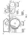
- Figure 1 is a diagrammatic illustration for applying a two-step transfix process in an ink jet printing system
- Figure 2 is diagram of a portion of a system incorporating features of the disclosed embodiments
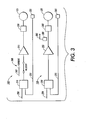
- Figure 3 is a schematic diagram of one embodiment of a transfer roll drive system and an imaging drum drive system in accordance with the disclosed embodiments;
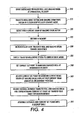
- Figure 4 is a flow chart of a learning, or set-up procedure for assembling a table for use by the transfer roll drive system during engagement and disengagement of the imaging drum and the transfer roll;
- FIGS 5-7 illustrate experimental data using the method of the present invention.
- Figure 1 discloses a diagrammatical illustration of an imaging apparatus 10 of the present invention for applying a two-step transfix process whereby a hot melt ink is printed onto an transfer surface for transference to a receiving substrate and then transported through a fuser for post fusing.
- a printhead 11 having ink jets supported by appropriate housing and support elements (not shown) for either stationary or moving utilization to deposit ink onto an intermediate transfer surface 12.
- the ink utilized is preferably initially in solid form and then changed to a molten state by the application of heat energy to raise the temperature from about 85 degrees to about 150 degrees centigrade. Elevated temperatures above this range will cause degradation or chemical breakdown of the ink.
- the molten ink is then applied in raster fashion from ink jets in the printhead 11 to the intermediate transfer surface 12 forming an ink image.
- the ink image is then cooled to an intermediate temperature and solidifies to a malleable state wherein it is transferred to a receiving substrate or media 28 and then post fused.
- a supporting surface 14 which is shown in Figure 1 has affixed an outer layer 9 defining a release surface.
- the intermediate transfer surface 12 is a liquid layer applied to the outer layer 9 on drum 14 by contact with an applicator assembly 16.
- applicator assembly 16 comprises a wicking roller impregnated with a release liquid for applying the liquid and a metering blade 18 for consistently metering the liquid on the surface of the drum 14.
- applicator assembly 16 is raised by the action of an applicator assembly cam and cam follower (not shown) until the wicking roller is in contact with the surface of the drum 14.
- the release liquid that forms the intermediate transfer surface 12 on outer layer 9 is heated by an appropriate heater device 19.
- the heater device 19 may be a radiant resistance heater positioned as shown or positioned internally within the drum 14. Heater device 19 increases the temperature of the intermediate transfer surface 12 from ambient temperature to between 25 degrees to about 70 degrees centigrade or higher to receive the ink from printhead 11. This temperature is dependent upon the exact nature of the liquid employed in the intermediate transfer surface 12 and the ink used and is adjusted by temperature controller 40 utilizing thermistor 42. Ink is then applied in molten form from about 85 degrees to about 150 degrees centigrade to the exposed surface of the liquid intermediate transfer surface 12 by the printhead 11 forming an ink image 26.
- the ink image 26 solidifies on the intermediate transfer surface 12 by cooling down to the malleable intermediate state temperature provided by heating device 19.
- a receiving substrate guide apparatus 20 then passes the receiving substrate 28, such as paper or transparency, from a positive feed device (not shown) and guides it through a nip 29.
- Opposing arcuate surfaces of a roller 23 and the drum 14 forms the nip 29.
- the roller 23 has a metallic core, preferably steel with an elastomer coating 22.
- the drum 14 continues to rotate, entering the nip 29 formed by the roller 22 with the curved surface of the intermediate transfer surface 12 containing the ink image 26.
- the ink image 26 is then deformed to its image conformation and adhered to the receiving substrate 28 by being pressed there against.
- the ink image 26 is first applied to the intermediate transfer surface 12 on the outer compliant surface 8 or rigid layer 9 and then transfixed off onto the receiving substrate or media 28.
- the ink image 26 is thus transferred and fixed to the receiving substrate 28 by the pressure exerted on it in the nip 29 by the resilient or elastomeric surface 22 of the roller 23.
- the pressure exerted may be less than 3558 N (800 lbf) on the receiving substrate or media.
- Stripper fingers 25 (only one of which is shown) may be pivotally mounted to the imaging apparatus 10 to assist in removing any paper or other final receiving substrate 28 from the exposed surface of the liquid layer forming the intermediate transfer surface 12.
- the applicator assembly 16 and metering blade 18 are actuated to raise upward into contact with the drum 14 to replenish the liquid intermediate transfer surface 12.
- a heater 21 may be used to preheat the receiving surface 28 prior to the fixation of the ink image 26.
- the heater 21 may be set to heat from between about 60 degrees to about 200 degrees centigrade. It is theorized that the heater 21 raises the temperature of the receiving medium to between about 90 degrees to about 100 degrees centigrade. However, the thermal energy of the receiving substrate 28 is kept sufficiently low so as not to melt the ink image upon transfer to the receiving substrate 28.
- the ink image 26 enters the nip 29 it is deformed to its image conformation and adheres to the receiving substrate 28 either by the pressure exerted against ink image 26 on the receiving substrate 28 or by the combination of the pressure and heat supplied by heater 21 and/or heater 19.
- a heater 24 may be employed which heats the transfer and fixing roller 23 to a temperature of between about 25 degrees to about 200 degrees centigrade. Heater devices 21 and 24 can also be employed in the paper or receiving substrate guide apparatus 20 or in the transfer and fixing roller 23, respectively.
- the pressure exerted on the ink image 26 must be sufficient to have the ink image 26 adhere to the receiving substrate 28 which is between about 10 to about 1.38 ⁇ 10 7 Pa (2000 pounds per square inch), and more preferably between about 5.17 ⁇ 10 6 to 5.86 ⁇ 10 6 Pa (750 to about 850 pounds per square inch).
- the ink image can then be thermally controlled with a thermal device 60.
- This thermal device 60 can heat, cool, or maintain the temperature of the receiving substrate 28 and ink image 26 which may by way of example be between 50 to 100 degrees C. The highest temperature the receiving substrate 28 and ink image 26 can be increased to in this location is dependent on the melting or flash point of the ink and/or the flash point of the receiving substrate 28.
- the thermal device 60 could be as simple as insulation to maintain the temperature of the ink and substrate as it exits the nip 29, or a heating and/or cooling system to add or remove thermal energy.
- the receiving substrate 28 and ink image 26 are then transported to a fuser 52.
- the fuser 52 is composed of a back-up roller 46 and a fuser roller 50.
- the back-up roller 46 and fuser roller 50 have metallic cores, preferable steel or aluminum, and may be covered with elastomer layers 54 and 56, respectively.
- the back-up roller 46 engages the receiving substrate 28 and ink image 26 on the reverse side to which the ink image 26 resides. This fuses the ink image 26 to the surface of the receiving substrate 28 so that the ink image 26 is spread, flattened, penetrated and adhered to the receiving substrate 28.
- the pressure exerted by the fuser may be between 445 N (100 lbf) to about 8896 N (2000 lbf) by way of example.
- the transfer roll When the transfer roll and the imaging drum come into contact, the transfer roll is driven preferably at a predetermined current (i.e. torque) level.
- the transfer roll system is generally adapted to cause the engagement and disengagement of a transfer roll with the imaging drum 14 during the image transfer process.
- the transfer roll system is generally adapted to cause the transfer roll to engage and disengage the imaging drum while maintaining a rotational velocity of the imaging drum at a nominal speed. It is a feature of the disclosed embodiments to provide a motor torque assist for the imaging drum to enable parallel imaging/transferring and reduce motion quality impacts of engagement and disengagement of the transfer roll.
- Imaging drum 14 includes a first pitch 15 and a second pitch 17.
- the boundaries between first and second pitches 15, 17 may be defined by one or more inter-document gaps 123.
- Imaging drum drive system 150 operates to maintain imaging drum 14 at a substantially constant rotational velocity.
- Printhead 11 generally operates to apply an image on at least one pitch 15 of imaging drum 14. Printhead 11 is capable of applying an image to both pitches, 15, 17.
- the transfer roll system includes a transfer roll 22, a transfer roll drive system 145, and an engagement assembly 140.
- Engagement assembly 140 is adapted to move transfer roll 22 into engagement with imaging drum 14 in the area of a nip 130 to transfer one or more images thereon to media 125.
- Media 125 may include any substrate suitable for applying images thereon and may comprise individual sheets or a continuous roll.
- one example of the motor torque assist includes measuring a drive current of imaging drum drive system 150, recording the drive current of transfer roll drive system 145 during transfer roll 22 and imaging drum 14 engagement and disengagement required to maintain the measured imaging drum drive current, and using the recorded drive current to operate transfer roll drive system 145 to minimize imaging drum velocity variations during subsequent engagement and disengagement.
- Controller 155 may include logic circuitry for generally controlling the operation of system 100, and include a processor 165 that operates programs in a memory device 170. Memory device 170 may also be capable of storing data.
- engagement assembly 140 may include an engagement motor 160 which operates to move transfer roll 22 toward or away from imaging drum 14.
- engagement motor 160 operates to move transfer roll 22 toward or away from imaging drum 14.
- Other engagement mechanisms and techniques may also be used so long as imaging drum 14 and transfer roll 22 are capable of being brought together and moved apart as described herein.
- Transfer roll drive system 145 is adapted to operate at least in a constant velocity mode and a current drive mode. In the constant velocity drive mode, transfer roll drive system 145 operates to maintain transfer roll 130 substantially at a particular rotational velocity. In the current drive mode, transfer roll drive system 145 operates to drive transfer roll 130 according to a current set point.
- Imaging drum drive system 150 is adapted to operate at least in a constant velocity mode, where imaging drum drive system 150 operates to maintain imaging drum 14 substantially at a particular rotational velocity.
- Figure 3 shows schematic diagrams of exemplary embodiments of transfer roll drive system 145 and imaging drum drive system 150.
- Transfer roll drive system 145 is adapted to operate at least in a constant velocity mode and a current drive mode. In the constant velocity drive mode, transfer roll drive system 145 operates to maintain transfer roll 22 substantially at a particular rotational velocity. In the current drive mode, transfer roll drive system 145 operates to drive transfer roll 130 according to a current set point.
- Transfer roll drive system 145 may include a transfer roll velocity servo controller 210, a transfer roll amplifier 215, a transfer roll motor 220, and a transfer roll velocity sensor 225.
- Controller 155 ( Figure 3 ) may apply a transfer roll velocity set point on signal line 230, and transfer roll velocity sensor 225 may apply a feedback signal on line 235.
- Transfer roll velocity servo controller 210 may then apply a signal to transfer roll amplifier 215 which in turn applies power to transfer roll motor 220.
- transfer roll velocity servo controller 210 When switch 240 is in the velocity position, transfer roll velocity servo controller 210 operates to maintain the velocity of transfer roll 22 substantially at the transfer roll velocity set point.
- transfer roll amplifier 215 When switch 240 is in the current position, transfer roll amplifier 215 operates as a current source, responsive to a current set point applied to signal line 245 by controller 155 ( Figure 3 ).
- Imaging drum drive system 150 is adapted to generally operate at least in a constant velocity mode. In the constant velocity drive mode, imaging drum drive system 150 operates to maintain imaging drum 14 substantially at a particular rotational velocity.
- Imaging drum drive system 150 may include an imaging drum velocity servo controller 250, an imaging drum amplifier 255, an imaging drum motor 260, and an imaging drum velocity sensor 265. Controller 155 ( Figure 3 ) may apply an imaging drum velocity set point on signal line 270, and imaging drum velocity sensor 265 may apply a feedback signal on line 275. Imaging drum velocity servo controller 250 may then apply a signal to imaging drum amplifier 255 which in turn applies power to imaging drum motor 260.
- Imaging drum drive system 150 may also include a current sensor 280 for sensing the current draw of imaging drum motor 260.
- printhead 11 applies a first image to pitch 15.
- engagement assembly 140 causes transfer roll 22 to move toward and engage imaging drum 14, forming nip 130. It is at this point that the transfer roll drive controller switches from constant velocity to constant current drive.
- sensor 500 As the lead edge of the media 125 approaches the nip 130, it is sensed by sensor 500.
- the torque assist controller 300 superimposes a positive pulse onto the constant current drive signal. This positive pulse is held for a predetermined time to counteract the torque disturbance imparted to the drum by the lead edge of the media. Similarly, the trail edge of the media is sensed and a negative pulse is superimposed on the constant current drive signal.
- the first image is transferred to media 125
- the second image may also be transferred to media 125 at nip 130. Otherwise, transfer roll 22 may be disengaged from imaging drum 14 when inter-document gap 123 reaches nip 130. When printhead 11 completes the second image application, transfer roll 22 and imaging drum 14 may then be re-engaged to transfer the second image to media 125. In either case, after the transfer roll is disengaged from the imaging drum, the control of the transfer roll returns to the constant velocity mode.
- Engagement and disengagement of transfer roll 22 and imaging drum 14 is generally performed when inter-document gap is at or near nip 130.
- a load in the range of approximately 226 - 317 kg (500-700 lbs.) may be applied to imaging drum 14.
- Full engagement, and thus full loading generally occurs as inter-document gap 123 traverses nip 130, which typically takes place in approximately 50 ms. Without compensating for this load change, the velocity of imaging drum 14 will fluctuate, causing motion quality problems.
- Motion quality requirements may dictate that imaging drum 14 remain within at least +/- 2% of its nominal velocity. Certain techniques used to apply images to imaging drum 14 may allow for some variation in imaging drum velocity, but generally may not be able to compensate for variations significantly larger than this range.
- the disclosed embodiments include driving transfer roll 22 in a manner that compensates for imaging drum velocity disturbances due to engagement and disengagement.
- the disclosed embodiments include a learning, or set-up procedure to record an amount of current applied to transfer roll drive system 145 to maintain a particular current draw of imaging drum drive system 150 during engagement and disengagement as shown in Figure 4 .
- the learning procedure may begin by driving disengaged transfer roll 22 and imaging drum 14 at their respective operational velocities with transfer roll drive system 145 and imaging drum drive system 150 both in a closed loop velocity control mode (step 315).
- a first current draw of imaging drum motor 260 as detected by current sensor 280 (step 320) is recorded by controller 155 in memory 170 (step 325).
- Transfer roll 22 and imaging drum 14 are incrementally moved toward each other. For example, by operating engagement motor 160 (step 330).
- transfer roll drive system 145 is switched to a current drive mode (step 335) where the current set point is initially set such that transfer roll 22 maintains its disengaged velocity (step 340).
- the current set point of transfer roll drive system 145 is adjusted during the engagement process so that the amount of current being drawn by imaging drum drive system 150 is maintained at the first current draw amount (step 345).
- the distance between transfer roll 22 and imaging drum 14, for example, as represented by a position of engagement motor 160, along with the corresponding current set point of transfer roll drive system 145 is recorded in memory 170 for each increment until transfer roll 22 and imaging drum 14 are completely engaged (step 350).
- the distances or positions and current set points may be assembled into a first lookup table 180 that correlates an amount of load compensating drive current with a distance between transfer roll 22 and imaging drum 14 (step 355).
- a similar learning procedure may be implemented for the disengagement of transfer roll 22 and imaging drum 14, that is, the distance between transfer roll 22 and imaging drum 14, along with the corresponding current set point of transfer roll drive system 145 is recorded in memory 170 for each incremental movement until transfer roll 22 and imaging drum 14 are completely disengaged, and the recordations may be assembled into a second lookup table 185.
- Second table 185 should be similar to first table 180 generated for the engagement operation.
- First and second lookup tables 180, 185 may be combined to form a single lookup table 190 that may be used for both engagement and disengagement of transfer roll 22 and imaging drum 14.
- Lookup table 180 may be utilized during later engagement and disengagement operations to minimize disturbances of the imaging drum velocity. For example, a subsequent marking operation may begin with transfer roll 22 and imaging drum 14 disengaged. Controller 155 may cause transfer roll drive system 145 to switch to a closed loop velocity control mode, and may cause disengaged transfer roll 22 and imaging drum 14 to operate at their respective operational velocities. Engagement motor 160 may then be successively incremented, moving transfer roll 22 toward imaging drum 14. As transfer roll 22 and imaging drum 14 begin to engage, transfer roll drive system 145 may be switched to a current drive mode. For each incremental movement, or distance between transfer roll 22 and imaging drum 14, for example, as represented by a position of engagement motor 160, the current set point for transfer roll drive system 145 is set according to look up table 180. Similarly, after image transfer is complete, during disengagement, as transfer roll 22 and imaging drum 14 are moving away from each other, the current set point for transfer roll drive system 145 for each distance between transfer roll 22 and imaging drum 14 may also be obtained from lookup table 180.
- lookup table 180 may be used for each engagement position and lookup table 185 may be used for each disengagement position.
- lookup table 190 may be used for each engagement position and disengagement position.
- memory device 170 may also include program storage devices 195 for storing software and computer programs incorporating the learning or setup procedure described above to execute by processor 165.
- the software and computer programs may be in the form of machine readable program source code.
- Controller 155 may be generally adapted to utilize program storage devices 195 embodying the machine readable program source code to perform the steps of the disclosed embodiments.
- Program storage devices 195 may include magnetic, optical, semiconductor, or any other type of suitable media.
- transfer roll 22 is driven to compensate for the load on imaging drum 14 to minimize any velocity variations that may occur as a result of the changes in load.
- the system 100 compensates for both transient rotational disturbances and steady state velocity changes due to the load changes associated with engagement and disengagement. Image mis-registration and other related motion quality problems are minimized.
- images may be formed on one or more pitches of imaging drum 14 while other images are being transferred from other pitches to media 125. Thus, image forming and image transferring operations may be performed in parallel, increasing system productivity.
- controller 155 includes a paper torque assist controller 300 is employed to maintain a constant velocity of the imaging drum when the lead edge of media enters nip 130 and when the trailing edge of the media exits nip 130.
- Paper torque assist controller 300 employs a pre-transfer paper sensor; sensor 500 detects when the lead edge of the media and trailing edge of the media enters the nip.
- paper torque assist controller In operation, when sensor 500 detects when the lead edge of the media; paper torque assist controller generates a signal command to increase the level of current commanded to the transfer roll drive motor for a predefined period to increase the velocity or transfer roll 22.
- additional torque is required to overcome the roll/drum separation when the lead edge initially enters the nip when the lead edge reaches a certain position the paper torque assist controller is disabled thereafter. Once the drum/roll are separated the additional torque requirement goes away.
- the trail edge of the paper leaves the nip, there will be an additional torque added to the system that causes the drum/roll to speed up until the nip closes after the paper.
- Torque assist controller 300 controller As the remaining portion of the media enters the nip the torque assist controller is enabled when the trailing edge of the media is sensed by sensor 500. Torque assist controller 300 controller generates a signal command to decrease the level of current commanded to the transfer roll drive motor for a second predefined period.
- Figure 5 illustrates Drum Velocity vs. Time for 140 um thick 40.7 kg (90 lb) media passing through closed transfix nip 335 kg (740 lb load) with no paper torque assist.
- the drum velocity varies by ⁇ 3% due to paper entering the closed roll/drum nip. Note that the drum velocity drops when the paper enters the nip and increases when the paper exits the nip.
- FIGs 6-7 illustrate Drum Velocity and Transfer Roll Drive Current vs time for 140 um thick 40.7 kg (90 lb) media passing through closed transfix nip 335 kg (740 lb load) with paper torque assist.
- Applicants have found that the velocity variation of the drum for the same paper is reduced from ⁇ 3% to ⁇ 1% - exceeding the spec of 2%.
- the commanded signal to the transfer roll is a step function and is delayed from the signal given by the pretransfer paper sensor.
- the response of the transfer roll motor to this input will have some dynamics that will affect the response of the system. This is adjusted for by changing the delay between the time when paper is detected by the pretransfer paper sensor and when the paper torque assist is started. Also notice that the step function of the paper torque assist is negative for paper leaving the nip.
- the three parameters that dictate the effectiveness of the paper torque assist method are: how long before paper enters the nip should the paper torque assist be turned on, how much additional torque is required to overcome the roll/drum separation, and how long after the paper enters the nip should the additional torque be maintained.
Landscapes
- Engineering & Computer Science (AREA)
- Multimedia (AREA)
- Signal Processing (AREA)
- Ink Jet (AREA)
- Electrostatic Charge, Transfer And Separation In Electrography (AREA)
- Ink Jet Recording Methods And Recording Media Thereof (AREA)
Claims (6)
- Verfahren zum Aufrechterhalten einer Drehgeschwindigkeit einer Abbildungstrommel (14) während eines Eingriffes mit einer Übertragungswalze (22) in einer Bilderzeugungsvorrichtung, umfassend:Bilden eines Walzenspaltes (130) zur Übertragung eines Bildes von der Abbildungstrommel (14) auf ein Medium (125), wenn die Abbildungstrommel (14) in Eingriff mit der Übertragungswalze (22) ist;Aufrechterhalten eines Modus der im Wesentlichen konstanten Drehgeschwindigkeit der Abbildungstrommel während eines Eingriffes mit der Übertragungswalze (22);Erfassen einer vorauseilenden Kante des Mediums (125) vor einem Eintritt in den Walzenspalt (130);gekennzeichnet durchAktivieren eines Drehmomentbeeinflussers zur Erhöhung der Geschwindigkeit der Übertragungswalze (22), wenn das Medium (125) in dem Walzenspalt (130) ist, während einer ersten definierten Zeitspanne; undWiederaufnehmen des Modus der im Wesentlichen konstanten Drehgeschwindigkeit der Abbildungstrommel, während ein Abschnitt des Mediums (125) in dem Walzenspalt (130) ist.
- Verfahren nach Anspruch 1, des Weiteren umfassend ein Erfassen einer nacheilenden Kante des Mediums (125) vor einem Eintritt in den Walzenspalt (130);
Aktivieren des Drehmomentbeeinflussers zum Erniedrigen der Geschwindigkeit der Übertragungswalze (22), wenn das Medium (125) in dem Walzenspalt (130) ist, während einer zweiten definierten Zeitspanne; und
Wiederaufnehmen des Modus der im Wesentlichen konstanten Drehgeschwindigkeit der Abbildungstrommel, nachdem das Medium (125) aus dem Walzenspalt (130) ausgetreten ist. - Verfahren nach Anspruch 1, wobei das Aktivieren des Drehmomentbeeinflussers ein Anpassen eines Stromeinstellpunktes eines Übertragungswalzenantriebes (145) zur Aufrechterhaltung einer im Wesentlichen konstanten Drehgeschwindigkeit der Abbildungstrommel, wenn das Medium (125) in den Walzenspalt (130) eintritt, beinhaltet.
- Verfahren nach Anspruch 2, wobei das Aktivieren des Drehmomentbeeinflussers ein Anpassen eines Stromeinstellpunktes eines Übertragungswalzenantriebes (145) zur Aufrechterhaltung einer im Wesentlichen konstanten Drehgeschwindigkeit der Abbildungstrommel, wenn das Medium (125) aus dem Walzenspalt (130) austritt, beinhaltet.
- Verfahren nach Anspruch 2, wobei das Erhöhen und Erniedrigen ein Anwenden einer auf Medienkenndaten beruhenden Tabelle (190) zur Bestimmung eines Antriebsstromes der Übertragungswalze zur Aufrechterhaltung der im Wesentlichen konstanten Drehgeschwindigkeit der Abbildungstrommel beinhaltet.
- Verfahren nach Anspruch 2, wobei die erste definierte Zeitspanne und die zweite definierte Zeitspanne eine auf Medienkenndaten beruhende Tabelle (190) zur Bestimmung von Zeitspannen zur Aufrechterhaltung der im Wesentlichen konstanten Drehgeschwindigkeit der Abbildungstrommel beinhaltet.
Applications Claiming Priority (2)
| Application Number | Priority Date | Filing Date | Title |
|---|---|---|---|
| US720781 | 1985-04-08 | ||
| US10/720,781 US7065308B2 (en) | 2003-11-24 | 2003-11-24 | Transfer roll engagement method for minimizing media induced motion quality disturbances |
Publications (2)
| Publication Number | Publication Date |
|---|---|
| EP1533990A1 EP1533990A1 (de) | 2005-05-25 |
| EP1533990B1 true EP1533990B1 (de) | 2009-07-01 |
Family
ID=34435826
Family Applications (1)
| Application Number | Title | Priority Date | Filing Date |
|---|---|---|---|
| EP04027783A Expired - Lifetime EP1533990B1 (de) | 2003-11-24 | 2004-11-23 | Einkupplungsverfahren für eine Übertragerrolle zum Verringern von Laufstörungen |
Country Status (6)
| Country | Link |
|---|---|
| US (1) | US7065308B2 (de) |
| EP (1) | EP1533990B1 (de) |
| JP (1) | JP5085843B2 (de) |
| CN (1) | CN1623774B (de) |
| CA (1) | CA2487845C (de) |
| DE (1) | DE602004021763D1 (de) |
Families Citing this family (55)
| Publication number | Priority date | Publication date | Assignee | Title |
|---|---|---|---|---|
| DE10322502A1 (de) * | 2003-05-19 | 2004-12-23 | OCé PRINTING SYSTEMS GMBH | Umdruckstation für ein elektrografisches Druck- oder Kopiergerät |
| US7113717B2 (en) * | 2004-03-30 | 2006-09-26 | Xerox Corporation | Closed loop control of nip pressure in a fuser system |
| KR100561367B1 (ko) * | 2004-10-21 | 2006-03-17 | 삼성전자주식회사 | 화상 형성 장치 및 이를 이용한 화상 형성 방법 |
| US7390084B2 (en) * | 2005-05-03 | 2008-06-24 | Xerox Corporation | Ink jet printer having multiple transfixing modes |
| US7907872B2 (en) * | 2005-07-29 | 2011-03-15 | Ricoh Company, Ltd. | Imprinting apparatus and an image formation apparatus |
| GB0517931D0 (en) * | 2005-09-02 | 2005-10-12 | Xaar Technology Ltd | Method of printing |
| US7654663B2 (en) | 2005-09-30 | 2010-02-02 | Xerox Corporation | Transfix roller load controlled by motor current |
| US7458671B2 (en) * | 2005-12-21 | 2008-12-02 | Xerox Corporation | Ink printer having improved release agent application control |
| US20080147578A1 (en) * | 2006-12-14 | 2008-06-19 | Dean Leffingwell | System for prioritizing search results retrieved in response to a computerized search query |
| JP5247391B2 (ja) * | 2007-12-14 | 2013-07-24 | キヤノン株式会社 | 画像形成装置 |
| JP2010139952A (ja) * | 2008-12-15 | 2010-06-24 | Fuji Xerox Co Ltd | 画像形成装置及びプログラム |
| US8317314B2 (en) * | 2010-03-09 | 2012-11-27 | Xerox Corporation | System and method for improving throughput for printing operations in an indirect printing system |
| US8317286B2 (en) * | 2010-03-09 | 2012-11-27 | Xerox Corporation | System and method for improving throughput for duplex printing operations in an indirect printing system |
| US8662657B2 (en) | 2011-04-08 | 2014-03-04 | Xerox Corporation | Print process for duplex printing with alternate imaging order |
| JP5773801B2 (ja) * | 2011-08-19 | 2015-09-02 | キヤノン株式会社 | インクジェット記録装置および該記録装置の制御方法 |
| US8714730B2 (en) * | 2011-12-13 | 2014-05-06 | Xerox Corporation | Method of selective drum maintenance in a drum maintenance unit in a printing apparatus |
| JP2013166299A (ja) * | 2012-02-15 | 2013-08-29 | Seiko Epson Corp | 液体噴射装置 |
| US11104123B2 (en) | 2012-03-05 | 2021-08-31 | Landa Corporation Ltd. | Digital printing system |
| CN104271687B (zh) | 2012-03-05 | 2016-11-02 | 兰达公司 | 油墨膜构造 |
| US9643403B2 (en) | 2012-03-05 | 2017-05-09 | Landa Corporation Ltd. | Printing system |
| US9498946B2 (en) | 2012-03-05 | 2016-11-22 | Landa Corporation Ltd. | Apparatus and method for control or monitoring of a printing system |
| US11106161B2 (en) | 2012-03-05 | 2021-08-31 | Landa Corporation Ltd. | Intermediate transfer members for use with indirect printing systems and protonatable intermediate transfer members for use with indirect printing systems |
| WO2013132418A2 (en) | 2012-03-05 | 2013-09-12 | Landa Corporation Limited | Digital printing process |
| CN109177531B (zh) | 2012-03-15 | 2020-11-27 | 兰达公司 | 打印系统的环形柔性皮带 |
| US8882223B2 (en) | 2012-07-31 | 2014-11-11 | Xerox Corporation | Method of printing with a split image revolution |
| US8696104B1 (en) | 2012-10-16 | 2014-04-15 | Xerox Corporation | Motion quality improvement by feed-forward torque control of imaging drum |
| CN103112264A (zh) * | 2013-03-04 | 2013-05-22 | 珠海天威飞马打印耗材有限公司 | 热转印方法及热转印装置 |
| US8827406B1 (en) | 2013-03-15 | 2014-09-09 | Xerox Corporation | Motion quality of a transfix nip by media thickness and/or skew feedforward to nip motor torque |
| GB201401173D0 (en) | 2013-09-11 | 2014-03-12 | Landa Corp Ltd | Ink formulations and film constructions thereof |
| US9415610B2 (en) * | 2014-06-23 | 2016-08-16 | Xerox Corporation | System and method for forming hydrophobic structures in a porous substrate |
| US9686540B2 (en) | 2014-06-23 | 2017-06-20 | Xerox Corporation | Robust colorimetric processing method for paper based sensors |
| GB2536489B (en) | 2015-03-20 | 2018-08-29 | Landa Corporation Ltd | Indirect printing system |
| GB2537813A (en) | 2015-04-14 | 2016-11-02 | Landa Corp Ltd | Apparatus for threading an intermediate transfer member of a printing system |
| DE112017002714T5 (de) | 2016-05-30 | 2019-02-28 | Landa Corporation Ltd. | Digitales Druckverfahren |
| GB201609463D0 (en) | 2016-05-30 | 2016-07-13 | Landa Labs 2012 Ltd | Method of manufacturing a multi-layer article |
| CN112428691B (zh) | 2016-05-30 | 2022-09-27 | 兰达公司 | 数字印刷方法和系统 |
| JP6864521B2 (ja) * | 2017-03-31 | 2021-04-28 | キヤノン株式会社 | 記録装置および制御方法 |
| JP6976091B2 (ja) * | 2017-07-04 | 2021-12-08 | キヤノン株式会社 | 記録装置及び制御方法 |
| JP6970541B2 (ja) * | 2017-07-04 | 2021-11-24 | キヤノン株式会社 | 記録装置、液吸収装置及び制御方法 |
| CN111032357B (zh) * | 2017-08-21 | 2022-03-18 | 曼罗兰纸张有限责任公司 | 带有多个主驱动马达的打印机的调节装置 |
| WO2019077489A1 (en) | 2017-10-19 | 2019-04-25 | Landa Corporation Ltd. | FLEXIBLE BELT WITHOUT END FOR A PRINTING SYSTEM |
| JP7225230B2 (ja) | 2017-11-19 | 2023-02-20 | ランダ コーポレイション リミテッド | デジタル印刷システム |
| WO2019102297A1 (en) | 2017-11-27 | 2019-05-31 | Landa Corporation Ltd. | Digital printing system |
| US11679615B2 (en) | 2017-12-07 | 2023-06-20 | Landa Corporation Ltd. | Digital printing process and method |
| WO2020003088A1 (en) | 2018-06-26 | 2020-01-02 | Landa Corporation Ltd. | An intermediate transfer member for a digital printing system |
| US10994528B1 (en) | 2018-08-02 | 2021-05-04 | Landa Corporation Ltd. | Digital printing system with flexible intermediate transfer member |
| US12001902B2 (en) | 2018-08-13 | 2024-06-04 | Landa Corporation Ltd. | Correcting distortions in digital printing by implanting dummy pixels in a digital image |
| JP7246496B2 (ja) | 2018-10-08 | 2023-03-27 | ランダ コーポレイション リミテッド | 印刷システムおよび方法に関する摩擦低減手段 |
| WO2020136517A1 (en) | 2018-12-24 | 2020-07-02 | Landa Corporation Ltd. | A digital printing system |
| JP7233987B2 (ja) * | 2019-03-13 | 2023-03-07 | キヤノン株式会社 | 画像形成装置 |
| EP3946953A4 (de) | 2019-03-31 | 2022-12-14 | Landa Corporation Ltd. | Systeme und verfahren zur verhinderung oder minimierung von druckdefekten in druckverfahren |
| CN114746813A (zh) | 2019-11-25 | 2022-07-12 | 兰达公司 | 在数字印刷中使用红外辐射来干燥油墨 |
| US11321028B2 (en) | 2019-12-11 | 2022-05-03 | Landa Corporation Ltd. | Correcting registration errors in digital printing |
| EP4081866A4 (de) | 2019-12-29 | 2024-01-03 | Landa Corporation Ltd. | Druckverfahren und -system |
| EP4264377A4 (de) | 2021-02-02 | 2024-11-13 | Landa Corporation Ltd. | Abschwächung von verzerrungen in druckbildern |
Family Cites Families (14)
| Publication number | Priority date | Publication date | Assignee | Title |
|---|---|---|---|---|
| US5389958A (en) | 1992-11-25 | 1995-02-14 | Tektronix, Inc. | Imaging process |
| JPH06274051A (ja) * | 1993-03-22 | 1994-09-30 | Fuji Xerox Co Ltd | 画像記録方法及びその装置 |
| US5325155A (en) | 1993-05-06 | 1994-06-28 | Eastman Kodak Company | Controlling the speed of an image-bearing member using relative states |
| JP3667788B2 (ja) | 1994-07-06 | 2005-07-06 | シャープ株式会社 | 画像形成装置 |
| JPH0915927A (ja) * | 1995-06-30 | 1997-01-17 | Fuji Xerox Co Ltd | 画像形成装置 |
| US6204865B1 (en) | 1997-07-15 | 2001-03-20 | Canon Kabushiki Kaisha | Color image forming apparatus timing control |
| KR100230318B1 (ko) * | 1997-07-30 | 1999-11-15 | 윤종용 | 레이저 프린터의 압력 조정장치 |
| KR100338760B1 (ko) * | 1999-09-01 | 2002-05-30 | 윤종용 | 간접전사방식 화상형성장치의 감광매체의 화상 밴딩 저감방법 |
| JP2001183915A (ja) * | 1999-12-22 | 2001-07-06 | Sharp Corp | 画像形成装置 |
| US6610721B2 (en) * | 2000-03-17 | 2003-08-26 | Novo Nordisk A/S | Imidazo heterocyclic compounds |
| JP2002072592A (ja) * | 2000-09-04 | 2002-03-12 | Canon Inc | 画像形成装置 |
| US6421513B1 (en) * | 2000-11-29 | 2002-07-16 | Xerox Corporation | Torque assist method and apparatus for reducing photoreceptor belt slippage in a printing machine |
| JP2003316177A (ja) * | 2002-04-22 | 2003-11-06 | Sharp Corp | 転写装置 |
| US6731891B1 (en) * | 2003-06-13 | 2004-05-04 | Xerox Corproation | Transfer roll engagement method for minimizing motion quality disturbances |
-
2003
- 2003-11-24 US US10/720,781 patent/US7065308B2/en not_active Expired - Fee Related
-
2004
- 2004-11-17 CA CA002487845A patent/CA2487845C/en not_active Expired - Fee Related
- 2004-11-19 JP JP2004335770A patent/JP5085843B2/ja not_active Expired - Fee Related
- 2004-11-23 EP EP04027783A patent/EP1533990B1/de not_active Expired - Lifetime
- 2004-11-23 DE DE602004021763T patent/DE602004021763D1/de not_active Expired - Lifetime
- 2004-11-24 CN CN2004100953742A patent/CN1623774B/zh not_active Expired - Fee Related
Also Published As
| Publication number | Publication date |
|---|---|
| CN1623774A (zh) | 2005-06-08 |
| JP5085843B2 (ja) | 2012-11-28 |
| US20050111861A1 (en) | 2005-05-26 |
| JP2005153525A (ja) | 2005-06-16 |
| CA2487845C (en) | 2007-08-07 |
| EP1533990A1 (de) | 2005-05-25 |
| CA2487845A1 (en) | 2005-05-24 |
| US7065308B2 (en) | 2006-06-20 |
| DE602004021763D1 (de) | 2009-08-13 |
| CN1623774B (zh) | 2013-07-03 |
Similar Documents
| Publication | Publication Date | Title |
|---|---|---|
| EP1533990B1 (de) | Einkupplungsverfahren für eine Übertragerrolle zum Verringern von Laufstörungen | |
| US4667208A (en) | Control system for a color printer | |
| US6390617B1 (en) | Image forming apparatus | |
| US20030103123A1 (en) | Continuous transfer and fusing application system | |
| EP2614962B1 (de) | Wärmeübertragungsdrucker | |
| CN101670704B (zh) | 用于在打印周期中移动转印辊的方法 | |
| KR101911098B1 (ko) | 간접 프린터에 사용하기 위한 이미지 전사 시스템 및 이미지 전사 시스템에 장착하도록 구성되는 교환 가능한 유닛 | |
| EP2087998B1 (de) | Wärmereguliertes Druckerelement, Verwendung eines Gummimaterials mit einem darin verteilten Phasenwechselmaterial, Drucker und Druckverfahren | |
| EP3099507B1 (de) | Drucksystem mit gleichmässiger heizung | |
| US10377128B2 (en) | Method for controlling a web in a printing apparatus | |
| US6527386B1 (en) | Compliant imaging surface for offset printing | |
| JP2009223229A (ja) | 画像形成装置 | |
| US6508551B1 (en) | Controlling transparency haze using a soft drum | |
| CN102729645B (zh) | 双面打印系统及操作打印机的方法 | |
| US8265533B2 (en) | Fuser release fluid rate transient control via variable speed oil metering system | |
| JP2013123885A (ja) | サーマルプリンタ、サーマルヘッドのクリーニング方法 | |
| JPS5940119B2 (ja) | 感熱転写記録装置 | |
| US10493772B2 (en) | Thermal transfer method and thermal transfer apparatus | |
| US9340057B1 (en) | Transfer device | |
| JPH1034987A (ja) | 熱転写記録装置及び熱転写記録方法 | |
| JP5017833B2 (ja) | プリンタ、およびサーマルヘッドのプレヒート制御方法 | |
| JP4947411B2 (ja) | プリンタ | |
| US9238375B2 (en) | Tape drive and method of operation | |
| JP2010039043A (ja) | 電子写真式印刷装置 | |
| JP2000263864A (ja) | カラープリンタおよびその用紙搬送方法 |
Legal Events
| Date | Code | Title | Description |
|---|---|---|---|
| PUAI | Public reference made under article 153(3) epc to a published international application that has entered the european phase |
Free format text: ORIGINAL CODE: 0009012 |
|
| AK | Designated contracting states |
Kind code of ref document: A1 Designated state(s): AT BE BG CH CY CZ DE DK EE ES FI FR GB GR HU IE IS IT LI LU MC NL PL PT RO SE SI SK TR |
|
| AX | Request for extension of the european patent |
Extension state: AL HR LT LV MK YU |
|
| 17P | Request for examination filed |
Effective date: 20050519 |
|
| AKX | Designation fees paid |
Designated state(s): DE FR GB |
|
| 17Q | First examination report despatched |
Effective date: 20071030 |
|
| GRAP | Despatch of communication of intention to grant a patent |
Free format text: ORIGINAL CODE: EPIDOSNIGR1 |
|
| GRAS | Grant fee paid |
Free format text: ORIGINAL CODE: EPIDOSNIGR3 |
|
| GRAA | (expected) grant |
Free format text: ORIGINAL CODE: 0009210 |
|
| AK | Designated contracting states |
Kind code of ref document: B1 Designated state(s): DE FR GB |
|
| REG | Reference to a national code |
Ref country code: GB Ref legal event code: FG4D |
|
| REF | Corresponds to: |
Ref document number: 602004021763 Country of ref document: DE Date of ref document: 20090813 Kind code of ref document: P |
|
| PLBE | No opposition filed within time limit |
Free format text: ORIGINAL CODE: 0009261 |
|
| STAA | Information on the status of an ep patent application or granted ep patent |
Free format text: STATUS: NO OPPOSITION FILED WITHIN TIME LIMIT |
|
| 26N | No opposition filed |
Effective date: 20100406 |
|
| REG | Reference to a national code |
Ref country code: FR Ref legal event code: PLFP Year of fee payment: 12 |
|
| REG | Reference to a national code |
Ref country code: FR Ref legal event code: PLFP Year of fee payment: 13 |
|
| PGFP | Annual fee paid to national office [announced via postgrant information from national office to epo] |
Ref country code: DE Payment date: 20161020 Year of fee payment: 13 Ref country code: GB Payment date: 20161027 Year of fee payment: 13 Ref country code: FR Payment date: 20161024 Year of fee payment: 13 |
|
| REG | Reference to a national code |
Ref country code: DE Ref legal event code: R119 Ref document number: 602004021763 Country of ref document: DE |
|
| GBPC | Gb: european patent ceased through non-payment of renewal fee |
Effective date: 20171123 |
|
| REG | Reference to a national code |
Ref country code: FR Ref legal event code: ST Effective date: 20180731 |
|
| PG25 | Lapsed in a contracting state [announced via postgrant information from national office to epo] |
Ref country code: FR Free format text: LAPSE BECAUSE OF NON-PAYMENT OF DUE FEES Effective date: 20171130 Ref country code: DE Free format text: LAPSE BECAUSE OF NON-PAYMENT OF DUE FEES Effective date: 20180602 |
|
| PG25 | Lapsed in a contracting state [announced via postgrant information from national office to epo] |
Ref country code: GB Free format text: LAPSE BECAUSE OF NON-PAYMENT OF DUE FEES Effective date: 20171123 |