EP1533497B1 - Lufteinlassvorrichtung für motor - Google Patents
Lufteinlassvorrichtung für motor Download PDFInfo
- Publication number
- EP1533497B1 EP1533497B1 EP03730861A EP03730861A EP1533497B1 EP 1533497 B1 EP1533497 B1 EP 1533497B1 EP 03730861 A EP03730861 A EP 03730861A EP 03730861 A EP03730861 A EP 03730861A EP 1533497 B1 EP1533497 B1 EP 1533497B1
- Authority
- EP
- European Patent Office
- Prior art keywords
- driven side
- side throttle
- opening
- electrically driven
- valve
- Prior art date
- Legal status (The legal status is an assumption and is not a legal conclusion. Google has not performed a legal analysis and makes no representation as to the accuracy of the status listed.)
- Expired - Lifetime
Links
- 230000001105 regulatory effect Effects 0.000 claims description 31
- 230000003111 delayed effect Effects 0.000 claims description 30
- 230000007246 mechanism Effects 0.000 claims description 26
- 230000007935 neutral effect Effects 0.000 claims description 8
- 230000008859 change Effects 0.000 claims description 7
- 239000000446 fuel Substances 0.000 description 11
- 238000001514 detection method Methods 0.000 description 8
- 230000005540 biological transmission Effects 0.000 description 7
- 230000006870 function Effects 0.000 description 6
- 230000000630 rising effect Effects 0.000 description 4
- 238000010586 diagram Methods 0.000 description 3
- 230000004048 modification Effects 0.000 description 3
- 238000012986 modification Methods 0.000 description 3
- 230000035939 shock Effects 0.000 description 3
- 238000001914 filtration Methods 0.000 description 2
- 230000001360 synchronised effect Effects 0.000 description 2
- 230000001133 acceleration Effects 0.000 description 1
- 230000000694 effects Effects 0.000 description 1
- 238000002347 injection Methods 0.000 description 1
- 239000007924 injection Substances 0.000 description 1
- 230000004044 response Effects 0.000 description 1
Images






Classifications
-
- F—MECHANICAL ENGINEERING; LIGHTING; HEATING; WEAPONS; BLASTING
- F02—COMBUSTION ENGINES; HOT-GAS OR COMBUSTION-PRODUCT ENGINE PLANTS
- F02D—CONTROLLING COMBUSTION ENGINES
- F02D9/00—Controlling engines by throttling air or fuel-and-air induction conduits or exhaust conduits
- F02D9/02—Controlling engines by throttling air or fuel-and-air induction conduits or exhaust conduits concerning induction conduits
-
- F—MECHANICAL ENGINEERING; LIGHTING; HEATING; WEAPONS; BLASTING
- F02—COMBUSTION ENGINES; HOT-GAS OR COMBUSTION-PRODUCT ENGINE PLANTS
- F02D—CONTROLLING COMBUSTION ENGINES
- F02D11/00—Arrangements for, or adaptations to, non-automatic engine control initiation means, e.g. operator initiated
- F02D11/02—Arrangements for, or adaptations to, non-automatic engine control initiation means, e.g. operator initiated characterised by hand, foot, or like operator controlled initiation means
-
- F—MECHANICAL ENGINEERING; LIGHTING; HEATING; WEAPONS; BLASTING
- F02—COMBUSTION ENGINES; HOT-GAS OR COMBUSTION-PRODUCT ENGINE PLANTS
- F02D—CONTROLLING COMBUSTION ENGINES
- F02D11/00—Arrangements for, or adaptations to, non-automatic engine control initiation means, e.g. operator initiated
- F02D11/06—Arrangements for, or adaptations to, non-automatic engine control initiation means, e.g. operator initiated characterised by non-mechanical control linkages, e.g. fluid control linkages or by control linkages with power drive or assistance
- F02D11/10—Arrangements for, or adaptations to, non-automatic engine control initiation means, e.g. operator initiated characterised by non-mechanical control linkages, e.g. fluid control linkages or by control linkages with power drive or assistance of the electric type
-
- F—MECHANICAL ENGINEERING; LIGHTING; HEATING; WEAPONS; BLASTING
- F02—COMBUSTION ENGINES; HOT-GAS OR COMBUSTION-PRODUCT ENGINE PLANTS
- F02D—CONTROLLING COMBUSTION ENGINES
- F02D11/00—Arrangements for, or adaptations to, non-automatic engine control initiation means, e.g. operator initiated
- F02D11/06—Arrangements for, or adaptations to, non-automatic engine control initiation means, e.g. operator initiated characterised by non-mechanical control linkages, e.g. fluid control linkages or by control linkages with power drive or assistance
- F02D11/10—Arrangements for, or adaptations to, non-automatic engine control initiation means, e.g. operator initiated characterised by non-mechanical control linkages, e.g. fluid control linkages or by control linkages with power drive or assistance of the electric type
- F02D11/105—Arrangements for, or adaptations to, non-automatic engine control initiation means, e.g. operator initiated characterised by non-mechanical control linkages, e.g. fluid control linkages or by control linkages with power drive or assistance of the electric type characterised by the function converting demand to actuation, e.g. a map indicating relations between an accelerator pedal position and throttle valve opening or target engine torque
-
- F—MECHANICAL ENGINEERING; LIGHTING; HEATING; WEAPONS; BLASTING
- F02—COMBUSTION ENGINES; HOT-GAS OR COMBUSTION-PRODUCT ENGINE PLANTS
- F02D—CONTROLLING COMBUSTION ENGINES
- F02D41/00—Electrical control of supply of combustible mixture or its constituents
- F02D41/0002—Controlling intake air
- F02D41/0005—Controlling intake air during deceleration
-
- F—MECHANICAL ENGINEERING; LIGHTING; HEATING; WEAPONS; BLASTING
- F02—COMBUSTION ENGINES; HOT-GAS OR COMBUSTION-PRODUCT ENGINE PLANTS
- F02D—CONTROLLING COMBUSTION ENGINES
- F02D41/00—Electrical control of supply of combustible mixture or its constituents
- F02D41/008—Controlling each cylinder individually
-
- F—MECHANICAL ENGINEERING; LIGHTING; HEATING; WEAPONS; BLASTING
- F02—COMBUSTION ENGINES; HOT-GAS OR COMBUSTION-PRODUCT ENGINE PLANTS
- F02D—CONTROLLING COMBUSTION ENGINES
- F02D9/00—Controlling engines by throttling air or fuel-and-air induction conduits or exhaust conduits
- F02D9/08—Throttle valves specially adapted therefor; Arrangements of such valves in conduits
- F02D9/10—Throttle valves specially adapted therefor; Arrangements of such valves in conduits having pivotally-mounted flaps
- F02D9/109—Throttle valves specially adapted therefor; Arrangements of such valves in conduits having pivotally-mounted flaps having two or more flaps
- F02D9/1095—Rotating on a common axis, e.g. having a common shaft
-
- F—MECHANICAL ENGINEERING; LIGHTING; HEATING; WEAPONS; BLASTING
- F02—COMBUSTION ENGINES; HOT-GAS OR COMBUSTION-PRODUCT ENGINE PLANTS
- F02B—INTERNAL-COMBUSTION PISTON ENGINES; COMBUSTION ENGINES IN GENERAL
- F02B61/00—Adaptations of engines for driving vehicles or for driving propellers; Combinations of engines with gearing
- F02B61/02—Adaptations of engines for driving vehicles or for driving propellers; Combinations of engines with gearing for driving cycles
-
- F—MECHANICAL ENGINEERING; LIGHTING; HEATING; WEAPONS; BLASTING
- F02—COMBUSTION ENGINES; HOT-GAS OR COMBUSTION-PRODUCT ENGINE PLANTS
- F02D—CONTROLLING COMBUSTION ENGINES
- F02D9/00—Controlling engines by throttling air or fuel-and-air induction conduits or exhaust conduits
- F02D9/02—Controlling engines by throttling air or fuel-and-air induction conduits or exhaust conduits concerning induction conduits
- F02D2009/0201—Arrangements; Control features; Details thereof
- F02D2009/0242—Increasing exhaust brake effect
-
- F—MECHANICAL ENGINEERING; LIGHTING; HEATING; WEAPONS; BLASTING
- F02—COMBUSTION ENGINES; HOT-GAS OR COMBUSTION-PRODUCT ENGINE PLANTS
- F02D—CONTROLLING COMBUSTION ENGINES
- F02D9/00—Controlling engines by throttling air or fuel-and-air induction conduits or exhaust conduits
- F02D9/02—Controlling engines by throttling air or fuel-and-air induction conduits or exhaust conduits concerning induction conduits
- F02D2009/0201—Arrangements; Control features; Details thereof
- F02D2009/0267—Arrangements; Control features; Details thereof for simultaneous action of a governor and an accelerator lever on the throttle
-
- F—MECHANICAL ENGINEERING; LIGHTING; HEATING; WEAPONS; BLASTING
- F02—COMBUSTION ENGINES; HOT-GAS OR COMBUSTION-PRODUCT ENGINE PLANTS
- F02D—CONTROLLING COMBUSTION ENGINES
- F02D9/00—Controlling engines by throttling air or fuel-and-air induction conduits or exhaust conduits
- F02D9/02—Controlling engines by throttling air or fuel-and-air induction conduits or exhaust conduits concerning induction conduits
- F02D2009/0201—Arrangements; Control features; Details thereof
- F02D2009/0279—Throttle valve control for intake system with two parallel air flow paths, each controlled by a throttle, e.g. a resilient flap disposed on a throttle
-
- F—MECHANICAL ENGINEERING; LIGHTING; HEATING; WEAPONS; BLASTING
- F02—COMBUSTION ENGINES; HOT-GAS OR COMBUSTION-PRODUCT ENGINE PLANTS
- F02D—CONTROLLING COMBUSTION ENGINES
- F02D11/00—Arrangements for, or adaptations to, non-automatic engine control initiation means, e.g. operator initiated
- F02D11/06—Arrangements for, or adaptations to, non-automatic engine control initiation means, e.g. operator initiated characterised by non-mechanical control linkages, e.g. fluid control linkages or by control linkages with power drive or assistance
- F02D11/10—Arrangements for, or adaptations to, non-automatic engine control initiation means, e.g. operator initiated characterised by non-mechanical control linkages, e.g. fluid control linkages or by control linkages with power drive or assistance of the electric type
- F02D2011/101—Arrangements for, or adaptations to, non-automatic engine control initiation means, e.g. operator initiated characterised by non-mechanical control linkages, e.g. fluid control linkages or by control linkages with power drive or assistance of the electric type characterised by the means for actuating the throttles
- F02D2011/102—Arrangements for, or adaptations to, non-automatic engine control initiation means, e.g. operator initiated characterised by non-mechanical control linkages, e.g. fluid control linkages or by control linkages with power drive or assistance of the electric type characterised by the means for actuating the throttles at least one throttle being moved only by an electric actuator
-
- F—MECHANICAL ENGINEERING; LIGHTING; HEATING; WEAPONS; BLASTING
- F02—COMBUSTION ENGINES; HOT-GAS OR COMBUSTION-PRODUCT ENGINE PLANTS
- F02D—CONTROLLING COMBUSTION ENGINES
- F02D11/00—Arrangements for, or adaptations to, non-automatic engine control initiation means, e.g. operator initiated
- F02D11/06—Arrangements for, or adaptations to, non-automatic engine control initiation means, e.g. operator initiated characterised by non-mechanical control linkages, e.g. fluid control linkages or by control linkages with power drive or assistance
- F02D11/10—Arrangements for, or adaptations to, non-automatic engine control initiation means, e.g. operator initiated characterised by non-mechanical control linkages, e.g. fluid control linkages or by control linkages with power drive or assistance of the electric type
- F02D2011/101—Arrangements for, or adaptations to, non-automatic engine control initiation means, e.g. operator initiated characterised by non-mechanical control linkages, e.g. fluid control linkages or by control linkages with power drive or assistance of the electric type characterised by the means for actuating the throttles
- F02D2011/103—Arrangements for, or adaptations to, non-automatic engine control initiation means, e.g. operator initiated characterised by non-mechanical control linkages, e.g. fluid control linkages or by control linkages with power drive or assistance of the electric type characterised by the means for actuating the throttles at least one throttle being alternatively mechanically linked to the pedal or moved by an electric actuator
-
- Y—GENERAL TAGGING OF NEW TECHNOLOGICAL DEVELOPMENTS; GENERAL TAGGING OF CROSS-SECTIONAL TECHNOLOGIES SPANNING OVER SEVERAL SECTIONS OF THE IPC; TECHNICAL SUBJECTS COVERED BY FORMER USPC CROSS-REFERENCE ART COLLECTIONS [XRACs] AND DIGESTS
- Y02—TECHNOLOGIES OR APPLICATIONS FOR MITIGATION OR ADAPTATION AGAINST CLIMATE CHANGE
- Y02T—CLIMATE CHANGE MITIGATION TECHNOLOGIES RELATED TO TRANSPORTATION
- Y02T10/00—Road transport of goods or passengers
- Y02T10/10—Internal combustion engine [ICE] based vehicles
- Y02T10/40—Engine management systems
Definitions
- a multiple cylinder engine mounted on a motorcycle includes an intake system of a multi-throttle type having one throttle body for each cylinder.
- a manual intake system in which a throttle grip and throttle valves are coupled mechanically by a throttle cable and all the throttle valves are opened and closed mechanically by a throttle grip rotating operation of a rider, is generally used.
- Engines like the above are for instance known from JP 11-241636 .
- the intake system is configured to learn a return opening range, in which the electrically driven side throttle valve is forcibly closed by the return mechanism, and drives the electric motor only in an opening range excluding the learned return opening range.
- the intake system learns a fully-closed position and a fully-opened position of the electrically driven side throttle valve and drives the electric motor only between the learned fully-closed position and fully-opened position.
- lock breakage of the electric motor which is caused by driving the electrically driven side throttle valve exceeding the fully-closed position and the fully-opened position, can be avoided.
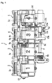
- reference numeral 1 denotes a carburetor unit constituting a hardware portion of the intake system of this embodiment.
- This carburetor unit 1 is formed by integrally combining first to fourth carburetors 2 to 5, which are connected to intake manifolds of first to fourth cylinders, with bolting.
- valve shaft 5c of the fourth carburetor 5 is coupled to an output shaft 11 a of an electric motor 11 via a link mechanism 10.
- this link mechanism 10 has a structure in which an arm 10a fixed to the valve shaft 5c and an arm 10c fixed to the output shaft 11 a are coupled by a bar-like link 10b so as to be rotatable relatively.
- the throttle valve 5b of the fourth carburetor 5 opens and closes the Venturi passage 5a according to the rotation of the electric motor 11.
- the throttle body 5d of the fourth carburetor 5 serves as an electrically driven side throttle body in which a throttle valve is driven to open and close by the electric motor 11. Therefore, in this embodiment, according to circumstances, the fourth throttle valve 5b is referred to as an electrically driven side throttle valve.
- a manually driven side opening sensor 13 which detects an opening of the throttle valve 2b, is mounted at the left end in Fig. 1 of the valve shaft 2c of the manually driven side throttle valve 2b of the first carburetor 2.
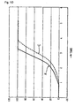
- the electrically driven side throttle valve 5b is forcibly closed to the vicinity of an opening 45% with a delay of very short time by the function of the return mechanism 12 (see B0 of a characteristic curve B). Thereafter, the electrically driven side throttle valve 5b is closed in a manner delayed by a first time constant by the function of the ECU 15 (see B1 of the characteristic curve B), temporarily opened to a shift-down time opening (e.g., about 45%, B2' of the characteristic curve B) when the motorcycle is decelerated from the sixth speed to the fifth speed, closed again in a manner delayed by the first time constant, and finally regulated to a regulated opening equivalent to about 20% of the full open (see B3 of the characteristic curve B).
- a shift-down time opening e.g., about 45%, B2' of the characteristic curve B
- the ECU 15 is adapted to open the electrically driven side throttle valve 5b in a manner delayed by a second time constant as the manually driven side throttle valves 2b to 4b open, that is, at the time of acceleration (see a characteristic curve C in Fig. 10 ). Note that it is needless to mention that various modifications can be adopted as the characteristic curve C by selecting the second time constant appropriately.
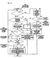
- step S24 if the brake is being applied in step S24, and when the detected manually driven side throttle valve opening is smaller than the brake time regulated opening (see B3 in Fig. 9 ), the ECU 15 sets the regulated opening as the opening instruction value of the electrically driven side throttle valve (steps S31 and S32). When the detected manually driven side throttle valve opening is not smaller than the brake time regulated opening, the ECU 15 returns to step S26.
- step S34 the ECU 15 sets an opening, which is obtained by delaying the detected manually driven side throttle valve opening by the second time constant (an opening obtained by filtering the manually driven side throttle valve opening, see the curve C in Fig. 10 ), as the opening instruction value of the electrically driven side throttle valve. (step S34). If the brake is being applied in step S27, the ECU 15 sets an opening, which is obtained by delaying the detected manually driven side throttle valve opening by the brake actuation time constant (B1 in Fig. 9 ) (an opening obtained by filtering the manually driven side throttle valve opening), as the instruction value (step S35).
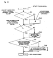
- the intake system learns a fully-closed position and a fully-opened position of the electrically driven side throttle valve 5b and drives the electric motor 11 only between the learned fully-closed position and fully-opened position.
- the problem in that the electrically driven side throttle valve 5b is driven exceeding the fully-closed position and the fully-opened position can be avoided, and breakage due to further energization in a lock state of the electric motor 11 can be avoided.
- an intake system for an engine includes plural throttle bodies having throttle valves for changing an intake passage area, wherein the plural throttle bodies are constituted by manually driven side throttle bodies having manually driven side throttle valves, which are opened and closed by a throttle operation of a rider, and an electrically driven side throttle body having an electrically driven side throttle valve, which is opened and closed by an electric motor, and the intake system includes valve opening control means that closes the electrically driven side throttle valve in a manner delayed by a first time constant within a range up to a predetermined regulated opening as the manually driven side throttle valves close.
- the learning of the fully-closed position is performed by, for example, in the case in which a detected opening of the electrically driven side throttle valve is larger than a fully-closed opening stored value, keeping the stored value as it is, and in the case in which the opening is smaller than the fully-closed opening stored value, updating the stored value.
- the learning of the fully-opened position is performed by, for example, in the case in which a detected opening of the electrically driven side throttle valve is smaller than a fully-opened opening stored value, keeping the stored value as it is, and in the case in which the opening is larger than the fully-opened opening stored value, updating the stored value.
- the valve opening control means closes the electrically driven side throttle valve in a manner delayed by a first time constant as the manually driven side throttle valves close.
Landscapes
- Engineering & Computer Science (AREA)
- Chemical & Material Sciences (AREA)
- Combustion & Propulsion (AREA)
- Mechanical Engineering (AREA)
- General Engineering & Computer Science (AREA)
- Control Of Throttle Valves Provided In The Intake System Or In The Exhaust System (AREA)
- Characterised By The Charging Evacuation (AREA)
- Electrical Control Of Air Or Fuel Supplied To Internal-Combustion Engine (AREA)
- Combined Controls Of Internal Combustion Engines (AREA)
- Motor Or Generator Cooling System (AREA)
- Control Of Vehicle Engines Or Engines For Specific Uses (AREA)
Claims (18)
- Einlasssystem für eine Brennkraftmaschine, das mehrere Drosselkörper (2, 3, 4, 5) enthält, parallel zueinander angeordnet, wobei jeder zumindest ein Drosselventil (2b, 3b, 4b, 5b) hat, um einen Einlasskanalquerschnitt (2a, 2b, 2c, 2d) zu verändern und eine Ventilwelle (2c, 3c, 4c, 5c), dadurch gekennzeichnet, dass die mehreren Drosselkörper (2, 3, 4) gebildet werden durch manuell angetriebene Drosselkörper (2, 3, 4), die manuell angetriebene Drosselventile (2b, 3b, 4b) haben, die durch eine manuelle Drosselbetätigung öffenbar oder schließbar sind und einen elektrisch angetriebene Drosselkörper (5), der ein elektrisch angetriebenes Drosselventil (5b) hat, das durch einen Elektromotor (11) öffenbar oder schließbar ist, wobei die Ventilwellen (2c, 3c, 4c) der ersten bis dritten Drosselkörper (2, 3, 4) gleichzeitig drehbar sind und die Ventilwelle (5c) des vierten Drosselkörpers (5) unabhängig drehbar ist, und dadurch, dass das Einlasssystem eine Ventilöffnungs- Steuerungsvorrichtung (15) enthält.
- Einlasssystem für eine Brennkraftmaschine nach Anspruch 1, dadurch gekennzeichnet, dass das Einlasssystem (1) von einem Multi- Drossel- Typ ist, das einen Drosselkörper (2, 3, 4, 5) für jeden Zylinder der Brennkraftmaschine hat.
- Einlasssystem für eine Brennkraftmaschine nach Anspruch 1 oder 2, dadurch gekennzeichnet, dass jeder Drosselkörper (2, 3, 4, 5) nur mit einem einzelnen Drosselventil (2b, 3b, 4b, 5b) versehen ist.
- Einlasssystem für eine Brennkraftmaschine nach zumindest einem der Ansprüche 1 bis 3, dadurch gekennzeichnet, dass zumindest ein Drosselventil (5b) unabhängig von den anderen Drosselventilen (2b, 3b, 4b) öffenbar oder schließbar ist.
- Einlasssystem für eine Brennkraftmaschine nach zumindest einem der Ansprüche 1 bis 4, dadurch gekennzeichnet, dass die Ventilöffnungs- Steuerungseinrichtung (15) konfiguriert ist, das elektrisch angetriebene Drosselventil (5b) in einer durch eine erste Zeitkonstante verzögerten Weise innerhalb eines Bereiches bis zu einer vorbestimmten geregelten Öffnung zu schließen, wenn das manuell angetriebene Drosselventil (5b) schließt.
- Einlasssystem für eine Brennkraftmaschine nach zumindest einem der Ansprüche 1 bis 5, dadurch gekennzeichnet, dass die Ventilöffnungs- Steuerungseinrichtung (15) konfiguriert ist, eine Verzögerung durch die erste Zeitkonstante zu der Zeit zu verändern, wenn eine Bremse betätigt wird, um größer zu sein als die Verzögerung durch die erste Zeitkonstante zu der Zeit, wenn die Bremse nicht betätigt wird, oder die geregelte Öffnung zu der Zeit zu verändern, wenn die Bremse betätigt wird, um größer zu sein, als eine geregelte Öffnung zu der Zeit, wenn die Bremse nicht betätigt wird.
- Einlasssystem für eine Brennkraftmaschine nach zumindest einem der Ansprüche 1 bis 6, dadurch gekennzeichnet, dass die Ventilöffnungs- Steuerungseinrichtung (15) konfiguriert, um zeitweilig das elektrisch angetriebene Drosselventil (5b) zu einer vorbestimmten Herunterschaltzeit- Öffnung zu der Zeit des Herunterschaltens zu öffnen, und anschließend das elektrisch angetriebene Drosselventil (5b) in einer durch eine erste Zeitkonstante verzögerten Weise zu schließen.
- Einlasssystem für eine Brennkraftmaschine nach zumindest einem der Ansprüche 1 bis 7, dadurch gekennzeichnet, dass die Ventilöffnungs- Steuerungseinrichtung (15) konfiguriert ist, eine Öffnung des elektrisch angetriebene Drosselventils (5b) derart zu steuern, dass eine bestimmte Ausgangscharakteristik, die einem Betriebszustand einer Brennkraftmaschine entspricht, erhalten wird und konfiguriert ist, vollständig- geschlossene Positionen der manuell angetriebene Drosselventile (2b, 3b, 4b) und des elektrisch angetriebene Drosselventils (5b) zu lernen, um die vollständiggeschlossenen Positionen miteinander identisch zu machen, wenn eine Drehzahl niedriger als eine vorbestimmte Lernzeitdrehzahl ist und eine Öffnung der manuell angetriebene Drosselventile (2b, 3b, 4b) kleiner als eine vorbestimmte Lernzeitöffnung ist.
- Einlasssystem für eine Brennkraftmaschine nach Anspruch 8, dadurch gekennzeichnet, dass das Einlasssystem konfiguriert ist, eine vollständig- geschlossene Positionen und eine vollständig- offene Positionen des elektrisch angetriebenen Seiten- Drosselventils (5b) zu lernen und um den Elektromotor (11) nur zwischen der gelernten vollständig- geschlossenen Positionen und der vollständig- geöffneten Positionen anzutreiben.
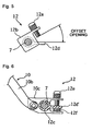
- Einlasssystem für eine Brennkraftmaschine nach zumindest einem der Ansprüche 1 bis 9, dadurch gekennzeichnet, dass die Ventilöffnungs- Steuerungseinrichtung (15) konfiguriert ist, eine Öffnung des elektrisch angetriebene Drosselventils (5b) derart zu steuern, dass eine Drehzahlausgangscharakteristik, die einem Betriebszustand einer Brennkraftmaschine entspricht, erhalten wird und dass eine mechanischer Rückkehrvorrichtung (12) vorgesehen ist, die in der Lage ist zwangsweise das elektrisch angetriebene Drosselventil (5b) auf eine vorbestimmte Rückkehröffnung zu schließen, wenn die manuell angetriebene Drosselventile (2b, 3b, 4b) schließen.
- Einlasssystem für eine Brennkraftmaschine nach Anspruch 10, dadurch gekennzeichnet, dass das Einlasssystem konfiguriert ist, einen Rückkehröffnungsbereich zu lernen, in dem das elektrisch angetriebene Drosselventil (5b) durch die Rückkehrvorrichtung (12) zwangsweise geschlossen wird und den Elektromotor (11) nur in einem Öffnungsbereich antreibt, der den gelernten Rückkehröffnungsbereich ausschließt.
- Einlasssystem für eine Brennkraftmaschine nach zumindest einem der Ansprüche 1 bis 11, dadurch gekennzeichnet, dass die Ventilöffnungs- Steuerungseinrichtung (15) konfiguriert ist, das elektrisch angetriebene Drosselventil (5b) in einer verzögerten Weise zu schließen, wenn die manuell angetriebene Drosselventile (2b, 3b, 4b) schließen und eine Verzögerung zu der Zeit zu verändern, wenn eine Bremse betätigt wird, um größer zu sein als eine Verzögerung zu der Zeit, wenn die Bremse nicht betätigt wird.
- Einlasssystem für eine Brennkraftmaschine nach zumindest einem der Ansprüche 1 bis 12, dadurch gekennzeichnet, dass die Ventilöffnungs- Steuerungseinrichtung (15) konfiguriert ist, das elektrisch angetriebene Drosselventil (5b) in einer verzögerten Weise zu schließen, wenn die manuell angetriebene Drosselventile (2b, 3b, 4b) schließen und um zeitweilig das elektrisch angetriebene Drosselventil (5b) auf eine vorbestimmte Herunterschaltzeitöffnung zu der Zeit des Herunterschaltens zu öffnen, und anschließend das elektrisch angetriebene Drosselventil (5b) später als die manuell angetriebene Drosselventile (2b, 3b, 4b) zu schließen.
- Einlasssystem für eine Brennkraftmaschine nach zumindest einem der Ansprüche 1 bis 13, dadurch gekennzeichnet, dass die Ventilöffnungs- Steuerungseinrichtung (15) konfiguriert ist, das elektrisch angetriebene Drosselventil (5b) einer innerhalb eines Bereiches bis zu einer vorbestimmten geregelten Öffnung in einer verzögerten Weise zu schließen, wenn die manuell angetriebene Drosselventile (2b, 3b, 4b) schließen.
- Einlasssystem für eine Brennkraftmaschine nach Anspruch 14, dadurch gekennzeichnet, dass die Ventilöffnungs- Steuerungseinrichtung (15) konfiguriert ist, das elektrisch angetriebene Drosselventil (5b) in einer durch die erste Zeitkonstante verzögerten Weise zu schließen, wenn die manuell angetriebene Drosselventile (2b, 3b, 4b) schließen.
- Einlasssystem für eine Brennkraftmaschine nach Anspruch 14 oder 15, dadurch gekennzeichnet, dass die Ventilöffnungs- Steuerungseinrichtung (15) konfiguriert ist, das elektrisch angetriebene Drosselventil (5b) in einer durch eine zweite Zeitkonstante verzögerten Weise zu öffnen, wenn die manuell angetriebene Drosselventile (2b, 3b, 4b) öffnen.
- Einlasssystem für eine Brennkraftmaschine nach zumindest einem der Ansprüche 1 bis 16, dadurch gekennzeichnet, dass die Ventilöffnungs- Steuerungseinrichtung (15) konfiguriert ist, eine Öffnung des elektrisch angetriebene Drosselventils (5b) identisch mit einer Öffnung der manuell angetriebene Drosselventile (2b, 3b, 4b) zu machen, wenn eine Drehzahl niedriger als eine vorbestimmte untere Steuergrenzzahl ist, oder ein Gang in der neutralen Stellung ist.
- Motorrad, aufweisend eine Mehrfachzylinder- Brennkraftmaschine mit einem Einlasssystem eines Multi- Drossel- Typs, dadurch gekennzeichnet, dass das Einlasssystem gemäß zumindest einem der Ansprüche 1 bis 17 konfiguriert ist.
Applications Claiming Priority (3)
| Application Number | Priority Date | Filing Date | Title |
|---|---|---|---|
| JP2002178279 | 2002-06-19 | ||
| JP2002178279 | 2002-06-19 | ||
| PCT/JP2003/007239 WO2004001209A1 (ja) | 2002-06-19 | 2003-06-06 | エンジンの吸気装置 |
Publications (3)
| Publication Number | Publication Date |
|---|---|
| EP1533497A1 EP1533497A1 (de) | 2005-05-25 |
| EP1533497A4 EP1533497A4 (de) | 2009-08-12 |
| EP1533497B1 true EP1533497B1 (de) | 2011-01-19 |
Family
ID=29996513
Family Applications (1)
| Application Number | Title | Priority Date | Filing Date |
|---|---|---|---|
| EP03730861A Expired - Lifetime EP1533497B1 (de) | 2002-06-19 | 2003-06-06 | Lufteinlassvorrichtung für motor |
Country Status (8)
| Country | Link |
|---|---|
| US (1) | US7112160B2 (de) |
| EP (1) | EP1533497B1 (de) |
| JP (1) | JP3984614B2 (de) |
| CN (1) | CN100400825C (de) |
| AT (1) | ATE496207T1 (de) |
| AU (1) | AU2003242034A1 (de) |
| DE (1) | DE60335804D1 (de) |
| WO (1) | WO2004001209A1 (de) |
Families Citing this family (13)
| Publication number | Priority date | Publication date | Assignee | Title |
|---|---|---|---|---|
| JP4318522B2 (ja) * | 2003-10-06 | 2009-08-26 | 本田技研工業株式会社 | 多気筒内燃機関 |
| JP2007154737A (ja) * | 2005-12-05 | 2007-06-21 | Denso Corp | 車両用エンジンの制御装置 |
| JP4634355B2 (ja) * | 2006-09-26 | 2011-02-16 | 本田技研工業株式会社 | 自動二輪車用内燃機関のスロットル制御装置 |
| JP4673876B2 (ja) * | 2007-09-29 | 2011-04-20 | 本田技研工業株式会社 | V型多気筒エンジンの吸気量制御装置 |
| FR2928758B1 (fr) | 2008-03-13 | 2012-10-12 | Mbda France | Systeme de routage de donnees. |
| JP5202415B2 (ja) * | 2009-03-31 | 2013-06-05 | 本田技研工業株式会社 | スロットル制御装置 |
| WO2013109814A1 (en) * | 2012-01-20 | 2013-07-25 | Cnh America Llc | Ride control system |
| JP5828517B2 (ja) * | 2012-03-28 | 2015-12-09 | 本田技研工業株式会社 | 多気筒エンジンの吸気制御装置 |
| JP5583258B1 (ja) * | 2013-09-26 | 2014-09-03 | 三菱電機株式会社 | スロットル学習制御装置 |
| US9714613B2 (en) * | 2015-08-10 | 2017-07-25 | Ford Global Technologies, Llc | Throttle adjustment during deceleration fuel shut off |
| JP6702358B2 (ja) * | 2018-06-08 | 2020-06-03 | スズキ株式会社 | 回転数制御装置 |
| JP7086132B2 (ja) * | 2020-04-30 | 2022-06-17 | 本田技研工業株式会社 | 制御装置 |
| US11448144B1 (en) * | 2021-03-16 | 2022-09-20 | Ford Global Technologies, Llc | Methods and system for controlling an engine with two throttles |
Family Cites Families (16)
| Publication number | Priority date | Publication date | Assignee | Title |
|---|---|---|---|---|
| DE3637561A1 (de) | 1985-11-18 | 1987-05-21 | Lisec Peter | Vorrichtung zum anbringen von flexiblen abstandhaltern auf glastafeln |
| JPS632839U (de) * | 1986-06-25 | 1988-01-09 | ||
| GB8723547D0 (en) * | 1987-10-07 | 1987-11-11 | Automotive Prod Plc | Clutch control |
| JPH0799097B2 (ja) * | 1987-12-22 | 1995-10-25 | 日産自動車株式会社 | 車両用駆動力制御装置 |
| US5151861A (en) * | 1989-02-22 | 1992-09-29 | Mitsubishi Jidosha Kogyo Kabushiki Kaisha | Vehicle engine output control method and vehicle engine |
| JPH0751903B2 (ja) * | 1989-09-05 | 1995-06-05 | 日産自動車株式会社 | 車両用エンジン出力制御装置 |
| JPH07112789B2 (ja) * | 1989-10-24 | 1995-12-06 | 日産自動車株式会社 | 車両走行制御装置 |
| JP2598333B2 (ja) * | 1990-06-26 | 1997-04-09 | 日産自動車株式会社 | スロットル開度検出装置 |
| JPH05149154A (ja) * | 1991-11-27 | 1993-06-15 | Hitachi Ltd | バルブ装置 |
| JP3189355B2 (ja) * | 1992-02-07 | 2001-07-16 | トヨタ自動車株式会社 | 自動変速機付車両の加速スリップ制御装置 |
| JPH06330780A (ja) * | 1993-05-21 | 1994-11-29 | Toyota Motor Corp | 車両用演算装置及び車両用演算方法 |
| US5520146A (en) * | 1995-03-03 | 1996-05-28 | Ford Motor Company | Electronic control system for single and series throttle valves |
| JPH11241636A (ja) | 1998-02-26 | 1999-09-07 | Yamaha Motor Co Ltd | 4サイクルエンジンの吸気装置 |
| JP2001090585A (ja) * | 1999-09-22 | 2001-04-03 | Denso Corp | 内燃機関のスロットル制御装置 |
| JP2002081328A (ja) * | 2000-09-06 | 2002-03-22 | Mikuni Corp | 内燃機関用スロットルボディ |
| JP3925073B2 (ja) * | 2000-10-27 | 2007-06-06 | スズキ株式会社 | 燃料噴射式エンジンの吸気制御装置 |
-
2003
- 2003-06-06 EP EP03730861A patent/EP1533497B1/de not_active Expired - Lifetime
- 2003-06-06 WO PCT/JP2003/007239 patent/WO2004001209A1/ja not_active Ceased
- 2003-06-06 CN CNB038095637A patent/CN100400825C/zh not_active Expired - Fee Related
- 2003-06-06 JP JP2004515479A patent/JP3984614B2/ja not_active Expired - Lifetime
- 2003-06-06 DE DE60335804T patent/DE60335804D1/de not_active Expired - Lifetime
- 2003-06-06 US US10/510,676 patent/US7112160B2/en not_active Expired - Lifetime
- 2003-06-06 AU AU2003242034A patent/AU2003242034A1/en not_active Abandoned
- 2003-06-06 AT AT03730861T patent/ATE496207T1/de not_active IP Right Cessation
Also Published As
| Publication number | Publication date |
|---|---|
| US7112160B2 (en) | 2006-09-26 |
| JP3984614B2 (ja) | 2007-10-03 |
| US20050153816A1 (en) | 2005-07-14 |
| CN1650099A (zh) | 2005-08-03 |
| ATE496207T1 (de) | 2011-02-15 |
| EP1533497A1 (de) | 2005-05-25 |
| WO2004001209A1 (ja) | 2003-12-31 |
| CN100400825C (zh) | 2008-07-09 |
| DE60335804D1 (de) | 2011-03-03 |
| AU2003242034A1 (en) | 2004-01-06 |
| JPWO2004001209A1 (ja) | 2005-10-20 |
| EP1533497A4 (de) | 2009-08-12 |
Similar Documents
| Publication | Publication Date | Title |
|---|---|---|
| US4703823A (en) | Vehicle running control system | |
| US7112160B2 (en) | Air intake system for engine | |
| US20090005943A1 (en) | Vehicle Speed Control System and Straddle-Type Vehicle | |
| US7267102B2 (en) | Engine control device and engine control method for straddle type vehicle | |
| US7461630B2 (en) | Electronic throttle valve control system and two-wheeled motor vehicle | |
| JP4745258B2 (ja) | 電子制御スロットル装置及び自動二輪車 | |
| US5060744A (en) | Device for controlling motor-operated throttle valve for automobiles | |
| JP2009174516A (ja) | 鞍乗型車両 | |
| US4860708A (en) | Throttle control system for automotive internal combustion engine | |
| EP2249010A2 (de) | Elektrische Gashebelvorrichtung für ein Motorrad | |
| KR910018250A (ko) | 자동차의 구동력 제어장치 및 제어방법 | |
| EP1719891B1 (de) | Elektronische Drosselklappensteuervorrichtung | |
| US6450918B1 (en) | Synchronous meshing type automatic transmission control system | |
| JPH06299875A (ja) | 制御弁制御装置 | |
| EP2407653A2 (de) | Kraftstoffeinspritzsteuerungssystem | |
| JPH0518278A (ja) | スロツトルバルブ駆動制御装置 | |
| JPH02230940A (ja) | スロットル制御装置 | |
| JPH01247721A (ja) | 機関のスロットル弁制御装置 | |
| JPH0350347A (ja) | 車載エンジンの制御弁装置 | |
| JP2582457B2 (ja) | 内燃機関のスロットル弁制御装置 | |
| JPH0612223Y2 (ja) | アクセルレバー制御装置 | |
| JP2876806B2 (ja) | 出力調整手段連係式モータ付スロットルバルブ装置 | |
| KR200153227Y1 (ko) | 메인 스로틀 엑츄에이터 | |
| JPH0370838A (ja) | スロットル駆動制御装置 | |
| JPH06264804A (ja) | 車両用制御装置 |
Legal Events
| Date | Code | Title | Description |
|---|---|---|---|
| PUAI | Public reference made under article 153(3) epc to a published international application that has entered the european phase |
Free format text: ORIGINAL CODE: 0009012 |
|
| 17P | Request for examination filed |
Effective date: 20041216 |
|
| AK | Designated contracting states |
Kind code of ref document: A1 Designated state(s): AT BE BG CH CY CZ DE DK EE ES FI FR GB GR HU IE IT LI LU MC NL PT RO SE SI SK TR |
|
| AX | Request for extension of the european patent |
Extension state: AL LT LV MK |
|
| DAX | Request for extension of the european patent (deleted) | ||
| A4 | Supplementary search report drawn up and despatched |
Effective date: 20090713 |
|
| 17Q | First examination report despatched |
Effective date: 20091015 |
|
| GRAP | Despatch of communication of intention to grant a patent |
Free format text: ORIGINAL CODE: EPIDOSNIGR1 |
|
| RIC1 | Information provided on ipc code assigned before grant |
Ipc: F02D 9/02 20060101AFI20100604BHEP Ipc: F02D 11/02 20060101ALI20100604BHEP Ipc: F02D 11/10 20060101ALI20100604BHEP |
|
| GRAS | Grant fee paid |
Free format text: ORIGINAL CODE: EPIDOSNIGR3 |
|
| GRAA | (expected) grant |
Free format text: ORIGINAL CODE: 0009210 |
|
| AK | Designated contracting states |
Kind code of ref document: B1 Designated state(s): AT BE BG CH CY CZ DE DK EE ES FI FR GB GR HU IE IT LI LU MC NL PT RO SE SI SK TR |
|
| REG | Reference to a national code |
Ref country code: GB Ref legal event code: FG4D |
|
| REG | Reference to a national code |
Ref country code: CH Ref legal event code: EP |
|
| REG | Reference to a national code |
Ref country code: IE Ref legal event code: FG4D |
|
| REF | Corresponds to: |
Ref document number: 60335804 Country of ref document: DE Date of ref document: 20110303 Kind code of ref document: P |
|
| REG | Reference to a national code |
Ref country code: DE Ref legal event code: R096 Ref document number: 60335804 Country of ref document: DE Effective date: 20110303 |
|
| REG | Reference to a national code |
Ref country code: NL Ref legal event code: VDEP Effective date: 20110119 |
|
| PG25 | Lapsed in a contracting state [announced via postgrant information from national office to epo] |
Ref country code: ES Free format text: LAPSE BECAUSE OF FAILURE TO SUBMIT A TRANSLATION OF THE DESCRIPTION OR TO PAY THE FEE WITHIN THE PRESCRIBED TIME-LIMIT Effective date: 20110430 Ref country code: GR Free format text: LAPSE BECAUSE OF FAILURE TO SUBMIT A TRANSLATION OF THE DESCRIPTION OR TO PAY THE FEE WITHIN THE PRESCRIBED TIME-LIMIT Effective date: 20110420 Ref country code: PT Free format text: LAPSE BECAUSE OF FAILURE TO SUBMIT A TRANSLATION OF THE DESCRIPTION OR TO PAY THE FEE WITHIN THE PRESCRIBED TIME-LIMIT Effective date: 20110519 Ref country code: SE Free format text: LAPSE BECAUSE OF FAILURE TO SUBMIT A TRANSLATION OF THE DESCRIPTION OR TO PAY THE FEE WITHIN THE PRESCRIBED TIME-LIMIT Effective date: 20110119 |
|
| PG25 | Lapsed in a contracting state [announced via postgrant information from national office to epo] |
Ref country code: SI Free format text: LAPSE BECAUSE OF FAILURE TO SUBMIT A TRANSLATION OF THE DESCRIPTION OR TO PAY THE FEE WITHIN THE PRESCRIBED TIME-LIMIT Effective date: 20110119 Ref country code: FI Free format text: LAPSE BECAUSE OF FAILURE TO SUBMIT A TRANSLATION OF THE DESCRIPTION OR TO PAY THE FEE WITHIN THE PRESCRIBED TIME-LIMIT Effective date: 20110119 Ref country code: CY Free format text: LAPSE BECAUSE OF FAILURE TO SUBMIT A TRANSLATION OF THE DESCRIPTION OR TO PAY THE FEE WITHIN THE PRESCRIBED TIME-LIMIT Effective date: 20110119 Ref country code: NL Free format text: LAPSE BECAUSE OF FAILURE TO SUBMIT A TRANSLATION OF THE DESCRIPTION OR TO PAY THE FEE WITHIN THE PRESCRIBED TIME-LIMIT Effective date: 20110119 Ref country code: AT Free format text: LAPSE BECAUSE OF FAILURE TO SUBMIT A TRANSLATION OF THE DESCRIPTION OR TO PAY THE FEE WITHIN THE PRESCRIBED TIME-LIMIT Effective date: 20110119 Ref country code: BE Free format text: LAPSE BECAUSE OF FAILURE TO SUBMIT A TRANSLATION OF THE DESCRIPTION OR TO PAY THE FEE WITHIN THE PRESCRIBED TIME-LIMIT Effective date: 20110119 Ref country code: BG Free format text: LAPSE BECAUSE OF FAILURE TO SUBMIT A TRANSLATION OF THE DESCRIPTION OR TO PAY THE FEE WITHIN THE PRESCRIBED TIME-LIMIT Effective date: 20110419 |
|
| PG25 | Lapsed in a contracting state [announced via postgrant information from national office to epo] |
Ref country code: DK Free format text: LAPSE BECAUSE OF FAILURE TO SUBMIT A TRANSLATION OF THE DESCRIPTION OR TO PAY THE FEE WITHIN THE PRESCRIBED TIME-LIMIT Effective date: 20110119 Ref country code: EE Free format text: LAPSE BECAUSE OF FAILURE TO SUBMIT A TRANSLATION OF THE DESCRIPTION OR TO PAY THE FEE WITHIN THE PRESCRIBED TIME-LIMIT Effective date: 20110119 |
|
| PLBE | No opposition filed within time limit |
Free format text: ORIGINAL CODE: 0009261 |
|
| STAA | Information on the status of an ep patent application or granted ep patent |
Free format text: STATUS: NO OPPOSITION FILED WITHIN TIME LIMIT |
|
| PG25 | Lapsed in a contracting state [announced via postgrant information from national office to epo] |
Ref country code: CZ Free format text: LAPSE BECAUSE OF FAILURE TO SUBMIT A TRANSLATION OF THE DESCRIPTION OR TO PAY THE FEE WITHIN THE PRESCRIBED TIME-LIMIT Effective date: 20110119 Ref country code: SK Free format text: LAPSE BECAUSE OF FAILURE TO SUBMIT A TRANSLATION OF THE DESCRIPTION OR TO PAY THE FEE WITHIN THE PRESCRIBED TIME-LIMIT Effective date: 20110119 Ref country code: RO Free format text: LAPSE BECAUSE OF FAILURE TO SUBMIT A TRANSLATION OF THE DESCRIPTION OR TO PAY THE FEE WITHIN THE PRESCRIBED TIME-LIMIT Effective date: 20110119 |
|
| 26N | No opposition filed |
Effective date: 20111020 |
|
| PG25 | Lapsed in a contracting state [announced via postgrant information from national office to epo] |
Ref country code: IT Free format text: LAPSE BECAUSE OF FAILURE TO SUBMIT A TRANSLATION OF THE DESCRIPTION OR TO PAY THE FEE WITHIN THE PRESCRIBED TIME-LIMIT Effective date: 20110119 |
|
| REG | Reference to a national code |
Ref country code: CH Ref legal event code: PL |
|
| REG | Reference to a national code |
Ref country code: DE Ref legal event code: R097 Ref document number: 60335804 Country of ref document: DE Effective date: 20111020 |
|
| REG | Reference to a national code |
Ref country code: IE Ref legal event code: MM4A |
|
| PG25 | Lapsed in a contracting state [announced via postgrant information from national office to epo] |
Ref country code: IE Free format text: LAPSE BECAUSE OF NON-PAYMENT OF DUE FEES Effective date: 20110606 Ref country code: CH Free format text: LAPSE BECAUSE OF NON-PAYMENT OF DUE FEES Effective date: 20110630 Ref country code: LI Free format text: LAPSE BECAUSE OF NON-PAYMENT OF DUE FEES Effective date: 20110630 |
|
| REG | Reference to a national code |
Ref country code: AT Ref legal event code: MK05 Ref document number: 496207 Country of ref document: AT Kind code of ref document: T Effective date: 20110119 |
|
| PG25 | Lapsed in a contracting state [announced via postgrant information from national office to epo] |
Ref country code: MC Free format text: LAPSE BECAUSE OF NON-PAYMENT OF DUE FEES Effective date: 20110630 |
|
| PG25 | Lapsed in a contracting state [announced via postgrant information from national office to epo] |
Ref country code: LU Free format text: LAPSE BECAUSE OF NON-PAYMENT OF DUE FEES Effective date: 20110606 |
|
| PG25 | Lapsed in a contracting state [announced via postgrant information from national office to epo] |
Ref country code: TR Free format text: LAPSE BECAUSE OF FAILURE TO SUBMIT A TRANSLATION OF THE DESCRIPTION OR TO PAY THE FEE WITHIN THE PRESCRIBED TIME-LIMIT Effective date: 20110119 |
|
| PG25 | Lapsed in a contracting state [announced via postgrant information from national office to epo] |
Ref country code: HU Free format text: LAPSE BECAUSE OF FAILURE TO SUBMIT A TRANSLATION OF THE DESCRIPTION OR TO PAY THE FEE WITHIN THE PRESCRIBED TIME-LIMIT Effective date: 20110119 |
|
| REG | Reference to a national code |
Ref country code: FR Ref legal event code: PLFP Year of fee payment: 14 |
|
| REG | Reference to a national code |
Ref country code: FR Ref legal event code: PLFP Year of fee payment: 15 |
|
| REG | Reference to a national code |
Ref country code: FR Ref legal event code: PLFP Year of fee payment: 16 |
|
| PGFP | Annual fee paid to national office [announced via postgrant information from national office to epo] |
Ref country code: GB Payment date: 20220622 Year of fee payment: 20 Ref country code: DE Payment date: 20220620 Year of fee payment: 20 |
|
| PGFP | Annual fee paid to national office [announced via postgrant information from national office to epo] |
Ref country code: FR Payment date: 20220628 Year of fee payment: 20 |
|
| REG | Reference to a national code |
Ref country code: DE Ref legal event code: R071 Ref document number: 60335804 Country of ref document: DE |
|
| REG | Reference to a national code |
Ref country code: GB Ref legal event code: PE20 Expiry date: 20230605 |
|
| P01 | Opt-out of the competence of the unified patent court (upc) registered |
Effective date: 20230527 |
|
| PG25 | Lapsed in a contracting state [announced via postgrant information from national office to epo] |
Ref country code: GB Free format text: LAPSE BECAUSE OF EXPIRATION OF PROTECTION Effective date: 20230605 |