EP1533005B1 - Kinetisches Therapiegerät mit schwingungsfähiger Plattform - Google Patents
Kinetisches Therapiegerät mit schwingungsfähiger Plattform Download PDFInfo
- Publication number
- EP1533005B1 EP1533005B1 EP04090455A EP04090455A EP1533005B1 EP 1533005 B1 EP1533005 B1 EP 1533005B1 EP 04090455 A EP04090455 A EP 04090455A EP 04090455 A EP04090455 A EP 04090455A EP 1533005 B1 EP1533005 B1 EP 1533005B1
- Authority
- EP
- European Patent Office
- Prior art keywords
- therapy apparatus
- platform
- support surface
- pendulums
- another
- Prior art date
- Legal status (The legal status is an assumption and is not a legal conclusion. Google has not performed a legal analysis and makes no representation as to the accuracy of the status listed.)
- Expired - Lifetime
Links
Images

Classifications
-
- A—HUMAN NECESSITIES
- A63—SPORTS; GAMES; AMUSEMENTS
- A63B—APPARATUS FOR PHYSICAL TRAINING, GYMNASTICS, SWIMMING, CLIMBING, OR FENCING; BALL GAMES; TRAINING EQUIPMENT
- A63B22/00—Exercising apparatus specially adapted for conditioning the cardio-vascular system, for training agility or co-ordination of movements
- A63B22/14—Platforms for reciprocating rotating motion about a vertical axis, e.g. axis through the middle of the platform
-
- A—HUMAN NECESSITIES
- A63—SPORTS; GAMES; AMUSEMENTS
- A63B—APPARATUS FOR PHYSICAL TRAINING, GYMNASTICS, SWIMMING, CLIMBING, OR FENCING; BALL GAMES; TRAINING EQUIPMENT
- A63B21/00—Exercising apparatus for developing or strengthening the muscles or joints of the body by working against a counterforce, with or without measuring devices
- A63B21/005—Exercising apparatus for developing or strengthening the muscles or joints of the body by working against a counterforce, with or without measuring devices using electromagnetic or electric force-resisters
- A63B21/0058—Exercising apparatus for developing or strengthening the muscles or joints of the body by working against a counterforce, with or without measuring devices using electromagnetic or electric force-resisters using motors
-
- A—HUMAN NECESSITIES
- A63—SPORTS; GAMES; AMUSEMENTS
- A63B—APPARATUS FOR PHYSICAL TRAINING, GYMNASTICS, SWIMMING, CLIMBING, OR FENCING; BALL GAMES; TRAINING EQUIPMENT
- A63B2208/00—Characteristics or parameters related to the user or player
- A63B2208/02—Characteristics or parameters related to the user or player posture
Definitions
- the invention relates to a kinetic therapy device with a vibratory platform and a support surface suspended from at least three pendulums according to the preamble of claim 1.
- the invention is based on the object to provide a vibratory platform that allows rotating vibrations and has only extremely low frictional force losses, the risk of entanglement of the user is reduced in the vibration device.
- a therapy device with a rotatable system consisting of a support surface (15) and a center and rigid on the Surface arranged support column (16), which in turn is rigidly connected at its upper end with said platform (17).
- Fig. 1 is a support frame 10 with supports 11 and 12 and a support 13 can be seen on the at least three pendulum 14, a support surface 15 is suspended, which in its center of area a rigidly connected to her Supporting rooms 16 carries, which in turn carries at its upper end a rigidly connected to said support column 16 platform 17.
- the rotational movement of the platform 17 may in principle also be superimposed on a translatory movement. If the translatory movement is not desired, it can be narrowed by a support guide 16 encompassing suitable guide 18 or possibly. Also completely prevented.
- the person to be treated positions himself on the platform 17 with one or both feet. Stimulated by impulses, the platform is put into a rotatory pendulum movement limited in its extent. The person to be treated must now try to adapt their posture to the movements of the platform 17. Numerous nerve and muscle areas are put into action, which are not used during the usual movement sequences. This is especially true for sensomotoric muscles of the pelvic and lumbar region, is desirable and leads to many areas Musculature to therapeutic stimuli and thus to desired and possibly necessary training effects.
- External rotation resistors - e.g. Starting from a roller cable or Theraband - can be easily transferred to the therapy level. It is also a rotational training for the popliteus muscle within a closed kinetic chain possible. The equilibrium reaction occurs predominantly in the limb and the trunk muscles.
- another platform can be placed on the platform 17, allowing a limited tilting movement about one of its diameters.
- the upper ankle is actively involved in the equilibrium reaction.
- focal points for different muscle chains can be realized.
- the rotation can also be transmitted from the outside, for example via a roller cable, in a simple manner to the therapy level.
- a grab handle 22 reaching in height up to about its hip can be provided.
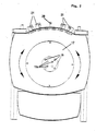
- Fig. 2 shows a plan view of a therapy device according to the invention. It can be seen that for the pendulum 14 suspension points 19 and 19a with different radii, ie with different distances to the center of the platform 17 and the support surface 15 can be selected, whereby the dynamic behavior of the platform 17 can be changed. Even if in the Fig. 2 only suspension points 19, 19a with two different radii (distances to the center) are shown, of course, suspension points 19, 19a can be provided on further radii.
- the respective rotational deflection of the platform 17 can be made visible via a display arm 20 connected to it for the trainee and his therapist. If necessary. the maximum rotational shocks of the platform 17 can also be limited by stops 21 for the display arm 20. This is often required especially in the first training phase.
- the pendulum 14 are suspended, which carry the support surface 15.
- the support surface 15 In the center of the surface of the support surface 15 which is rigidly connected to the support surface 15 supporting column 16 is arranged, which in turn - as from Fig. 1 recognizable - the rigidly connected to her platform 17 carries.
- the support surface 15 According to the suspension points 19, 19a of the platform 17, the support surface 15 has associated suspension points 19, 19a.
- the sensitivity of the suspension can also be influenced by the fact that the pendulum 14 between the suspension points 19 of the platform 17 with a larger radius and the suspension points 19a with a smaller radius of the support surface 15 or vice versa are arranged.
- pendulum 15 such according to EP 0 259 325 B1 proved to be particularly advantageous. But it can also be common rope pendulum made of textile or plastic materials or braided steel wire used.
- Multiple platforms can be placed side-by-side at the same height or heights so that the user can train on a plane or on a simulated staircase. This results in rotationally a two-sided knee load.
- the rotation can also be stimulated manually by a cam drive, by magnetic forces or manually by the therapist rhythmically.
- the pendulums can also be provided more than three pendulums. If necessary, the pendulums can also be made of textile or plastic materials.
- the support column 16 may be surrounded by a guide 18 restricting or preventing the translatory movements.
- Different, mutually associated groups of suspension points 19, 19a on different radii of the support surface 15 and the platform 17 may be provided.
- the possibly required hold for the patient is conveyed by a grab handle 22 that extends approximately to the waist height.
- the high-frequency oscillation of the therapy level triggers efferent impulses of enormous irritation density on the stabilizing musculature out.
- the stimulus response of the musculature is practically metrologically detectable throughout the body as rhythmic stabilization. It results in a coordinative training effect of considerable effectiveness, without the need for complicated exercise instructions.
- the therapy device is very well suited.
Landscapes
- Health & Medical Sciences (AREA)
- Cardiology (AREA)
- Vascular Medicine (AREA)
- General Health & Medical Sciences (AREA)
- Physical Education & Sports Medicine (AREA)
- Rehabilitation Tools (AREA)
- Radiation-Therapy Devices (AREA)
- Percussion Or Vibration Massage (AREA)
Description
- Die Erfindung bezieht sich auf ein kinetisches Therapiegerät mit schwingungsfähiger Plattform und einer an mindestens drei Pendeln aufgehängten Stützfläche gemäß Oberbegriff des Anspruchs 1.
- Im Therapiebereich besteht der vielfache Wunsch nach dynamisch gelagerten Plattformen. Es hat sich nämlich gezeigt, dass eine Vielzahl von körperlichen Unzulänglichkeiten oder Beschwerden mit dynamisch gelagerten Ebenen erfolgreich therapiert werden kann.
- So ist aus therapeutischen Gründen insbesondere das Bedürfnis nach rotationsfähigen Plattformen vorhanden, ohne dass in dieser Hinsicht bisher wirklich befriedigende Lösungen gefunden wurden.
- Aus der
DE 297 13 930 U1 und derFR 2 654 942 A1 - Der Erfindung liegt die Aufgabe zu Grunde, eine schwingungsfähige Plattform zu schaffen, die rotierende Schwingungen ermöglicht und nur extrem geringe Reibkraftverluste aufweist, wobei das Risiko eines Verhakens des Benutzers in der Schwingungsvorrichtung reduziert ist.
- Zur Lösung dieser Aufgabe wird gemäß kennzeichnendem Teil des Anspruchs 1 ein Therapiegerät mit einem rotationsfähigen System vorgeschlagen, das aus einer Stützfläche (15) und einer mittig und starr auf deren Oberfläche angeordneten Stützsäule (16) besteht, die ihrerseits an ihrem oberen Ende starr mit der erwähnten Plattform (17) verbunden ist.
- Damit wird erreicht, dass die pendelnd aufgehängte Stützfläche und damit auch die mit ihr starr verbundene Plattform praktisch reibungsfreie Rotationsbewegungen ausführen kann.
- Überlagerte geringfügige translatorische Bewegungen stören dabei im Allgemeinen nicht. Sollte das jedoch der Fall sein, so können die translatorischen Bewegungen durch eine den Außenumfang der Stützsäule mit entsprechendem Spiel umfassende Führung weitgehend eingeengt oder vollständig ausgeschaltet werden.
- Die Erfindung wird nachfolgend unter Bezugnahme auf die Zeichnungsfiguren beschrieben. Es zeigen
- Fig. 1
- ein Gestell mit einer rotationsfähigen Plattform, die über eine Stützsäule starr mit einer Stützplatte verbunden ist, die ihrerseits über Pendel an einem Gestell aufgehängt ist,
- Fig. 2
- eine Draufsicht auf ein solches Gestell, sowie
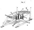
- Fig. 3
- eine perspektivische Sicht auf die Unterseite des Gestells, wobei Teile des Gestells weggebrochen sind, um die Stützplatte und ihre Aufhängung besser veranschaulichen zu können.
- In
Fig. 1 ist ein Traggestell 10 mit Stützen 11 und 12 sowie einem Träger 13 erkennbar, an dem über mindestens drei Pendel 14 eine Stützfläche 15 aufgehängt ist, die in ihrer Flächenmitte eine starr mit ihr verbundene Stützsäle 16 trägt, die wiederum an ihrem oberen Ende eine starr mit der erwähnten Stützsäule 16 verbundene Plattform 17 trägt. Bei einer solchen Anordnung kann der Rotationsbewegung der Plattform 17 grundsätzlich auch eine translatorische Bewegung überlagert sein. Sofern die translatorische Bewegung nicht erwünscht ist, kann diese durch eine die Stützsäule 16 umgreifende geeignete Führung 18 eingeengt oder ggfs. auch vollständig verhindert werden. - Die zu therapierende Person stellt sich mit einem oder auch mit beiden Füßen auf die Plattform 17. Angeregt durch Impulse wird die Plattform in eine in ihrem Ausmaß begrenzte, rotatorische Pendelbewegung versetzt. Die zu therapierende Person muss nunmehr versuchen, ihre Körperhaltung den Bewegungen der Plattform 17 anzupassen. Dabei werden zahlreiche Nerven- und Muskelbereiche in Tätigkeit versetzt, die während der üblichen Bewegungsabläufe nicht in Anspruch genommen werden. Dies gilt insbesondere für Muskeln der Sensomotorik der Becken- und Lumbalregion, ist erwünscht und führt für viele Bereiche der Muskulatur zu therapeutischen Reizen und damit zu erwünschten und ggfs. notwendigen Trainingseffekten.
- Externe Rotationswiderstände - z.B. von einem Rollenseilzug oder Theraband ausgehend - lassen sich auf einfache Weise auf die Therapieebene übertragen. Es ist auch ein rotatorisches Training für den Muskel popliteus innerhalb einer geschlossenen kinetischen Kette möglich. Die Gleichgewichtsreaktion erfolgt überwiegend in der Extremität sowie der Rumpfmuskulatur.
- Sofern erwünscht, kann auf der Plattform 17 auch eine weitere Plattform angeordnet werden, die um einen ihrer Durchmesser herum eine begrenzte Kippbewegung zulässt. Hier ist dann auch das obere Sprunggelenk aktiv in die Gleichgewichtsreaktion eingebunden. Je nach vorgewählter Kipprichtung lassen sich Schwerpunkte für unterschiedliche Muskelketten realisieren. Die Rotation kann auch von außen, beispielsweise über einen Rollenseilzug, auf einfache Weise auf die Therapieebene übertragen werden.
- Um dem Trainierenden bei den Übungen eine gewisse Hilfe zu geben, kann ein in der Höhe bis etwa zu seiner Hüfte reichender Haltegriff 22 vorgesehen werden.
-
Fig. 2 zeigt eine Draufsicht auf ein erfindungsgemäßes Therapiegerät. Es ist erkennbar, dass für die Pendel 14 Aufhängepunkte 19 bzw. 19a mit unterschiedlichen Radien, d.h. mit unterschiedlichen Abständen zum Mittelpunkt der Plattform 17 bzw. der Stützfläche 15 gewählt werden können, wodurch sich das dynamische Verhalten der Plattform 17 verändern lässt. Auch wenn in derFig. 2 nur Aufhängepunkte 19, 19a mit zwei unterschiedlichen Radien (Abstände zum Mittelpunkt) dargestellt sind, können selbstverständlich auch Aufhängepunkte 19, 19a auf weiteren Radien vorgesehen werden. - Der jeweilige Rotationsausschlag der Plattform 17 kann über einen mit ihr verbundenen Anzeigearm 20 für den Trainierenden und dessen Therapeuten sichtbar gemacht werden. Ggfs. können die maximalen Rotationsschläge der Plattform 17 auch durch Anschläge 21 für den Anzeigearm 20 begrenzt werden. Dies ist insbesondere in der ersten Trainingsphase häufig erforderlich.
- Das weiter oben zu den
Fig. 1 und2 Beschriebene wird in derFig. 3 noch einmal verdeutlicht. Am Träger 13 sind die Pendel 14 aufgehängt, die die Stützfläche 15 tragen. In der Flächenmitte der Stützfläche 15 ist die starr mit der Stützfläche 15 verbundene Stützsäule 16 angeordnet, die ihrerseits - wie ausFig. 1 erkennbar - die starr mit ihr verbundene Plattform 17 trägt. Entsprechend den Aufhängepunkten 19, 19a der Plattform 17 weist auch die Stützfläche 15 zugeordnete Aufhängepunkte 19, 19a auf. Die Sensibilität der Aufhängung kann aber auch dadurch beeinflusst werden, dass die Pendel 14 zwischen den Aufhängepunkten 19 der Plattform 17 mit größerem Radius und den Aufhängepunkten 19a mit kleinerem Radius der Stützfläche 15 oder umgekehrt angeordnet werden. - Als Pendel 15 haben sich solche gemäß
EP 0 259 325 B1 als besonders vorteilhaft erwiesen. Es können aber auch übliche Seilpendel aus Textil- oder Kunststoffmaterialien bzw. aus geflochtenem Stahldraht zur Anwendung kommen. - Zur Beeinflussung des Schwingverhaltens können auch sogenannte "Gegenpendel" zum Einsatz kommen, wie sie in Spalten 2 und 3 der
EP 0 102 546 B1 in Verbindung mit derFig. 1 beschrieben sind. - Mehrere Plattformen können in gleicher Höhe oder in unterschiedlichen Höhen nebeneinander angeordnet werden, so dass der Nutzer eine Fortbewegung in einer Ebene oder auf einer simulierten Treppe trainieren kann. Dabei ergibt sich rotatorisch eine beidseitige Kniebelastung.
- Je nach gewünschtem Therapie-Effekt kann die Rotation auch motorisch durch einen Nockenantrieb, über Magnetkräfte oder vom Therapeuten manuell rhythmisch angeregt werden.
- Es können auch mehr als drei Pendel vorgesehen werden. Die Pendel können ggfs. auch aus Textil- oder Kunststoffmaterialen bestehen.
- Über ein Gegenpendel - wie es in
Fig. 1 derEP 0 102 546 B1 gezeigt wird - kann das Bewegungsverhalten der Plattform 17 zusätzlich beeinflusst werden. - Die Stützsäule 16 kann von einer die translatorischen Bewegungen einengenden oder verhindernden Führung 18 umgeben sein.
- Es können verschiedene, einander zugeordnete Gruppen von Aufhängepunkten 19, 19a auf unterschiedlichen Radien der Stützfläche 15 und der Plattform 17 vorgesehen werden.
- Es können auch ein die jeweilige rotatorische Positionierung der Plattform 17 veranschaulichender Anzeigearm 20 sowie die rotatorische Bewegung der Plattform 17 begrenzende Anschläge 21 vorgesehen werden.
- Auch mehrere Plattformen in gleicher oder unterschiedlicher Höhe nebeneinander sind denkbar.
- Den ggfs. erforderlichen Halt für den Patienten vermittelt ein etwa bis zur Hüfthöhe reichender Haltegriff 22.
- Bei Benutzung der Plattform 17 kommt es zu rotatorischen Pendelbewegungen, die insbesondere bei Ungeübten zu erheblichen Ausschlägen führen, Allein derjenige, dem es gelingt, seinen Körperschwerpunkt ruhig und konzentriert innerhalb des Zentrums seiner Unterstützungsfläche zu stabilisieren, vermag zu einem ruhigen Stand zu kommen. Wie schwierig die Bewältigung dieser zunächst einfach erscheinenden Aufgabe ist, zeigt sich daran, dass nur ganz wenige Patienten beim ersten Versuch zu einem befriedigenden Ergebnis kommen.
- Die hochfrequente Schwingung der Therapierebene löst efferente Impulse enormer Reizdichte an der stabilisierenden Muskulatur aus. Die Reizantwort der Muskulatur ist praktisch im ganzen Körper meßtechnisch als rhythmische Stabilisation nachweisbar. Es ergibt sich ein koordinativer Trainingseffekt von erheblicher Effektivität, ohne dass komplizierte Übungsanweisungen notwendig sind.
- Insbesondere für Patienten mit Wirbelsäulenbeschwerden ist das Therapiegerät sehr gut geeignet.
Claims (14)
- Therapiegerät mita) einer schwingungsfähigen Plattform (17) undb) einer an mindestens drei Pendeln (14) aufgehängten Stützfläche (15), dadurch gekennzeichnet, dassc) ein rotationsfähiges System vorhanden ist,d) bestehend aus der Stützfläche (15) unde) einer mittig und starr auf ihrer Oberfläche mit ihr verbundenen Stützsäule (16), die ihrerseits an ihrem oberen Ende starr mit der zuvor erwähnten schwingungsfähigen Plattform (17) verbunden ist.
- Therapiegerät nach Anspruch 1, dadurch gekennzeichnet, dass vier Pendel (14) vorhanden sind.
- Therapiegerät nach einem der Ansprüche 1 oder 2, dadurch gekennzeichnet, dass die Pendel aus Textil- oder Kunststoffmaterialien bestehen.
- Therapiegerät, nach einem der Ansprüche 1 oder 2, dadurch gekennzeichnet, dass die Pendel aus geflochtenem Stahldraht bestehen.
- Therapiegerät nach einem der Ansprüche 1 bis 4, dadurch gekennzeichnet, dass ein Gegenpendel vorhanden ist.
- Therapiegerät nach einem der Ansprüche 1 bis 5, dadurch gekennzeichnet, dass die Stützsäule (16) von einer die translatorischen Bewegungen einengenden bzw. verhindernden Führung (18) umgeben ist.
- Therapiegerät nach einem der Ansprüche 1 bis 6, dadurch gekennzeichnet, dass verschiedene, einander zugeordnete Gruppen von Aufhängepunkten (19, 19a) auf unterschiedlichen Radien der Stützfläche (15) und der Plattform (17) angeordnet sind.
- Therapiegerät nach einem der Ansprüche 1 bis 7, dadurch gekennzeichnet, dass ein die jeweilige rotatorische Positionierung der Plattform (17) veranschaulichender Anzeigearm (20) vorhanden ist.
- Therapiegerät nach einem der Ansprüche 1 bis 8, dadurch gekennzeichnet, dass die rotatorische Bewegung der Plattform (17) begrenzende Anschläge (21) vorhanden sind.
- Therapiegerät nach Anspruch 9, dadurch gekennzeichnet, dass die Anschläge verstellbar sind.
- Therapiegerät nach einem der Ansprüche 1 bis 10, dadurch gekennzeichnet, dass mehrere Plattformen (17) nebeneinander angeordnet sind.
- Therapiegerät nach Anspruch 11, dadurch gekennzeichnet, dass die Plattformen (17) in gleicher Höhe nebeneinander angeordnet sind.
- Therapiegerät nach einem der Ansprüche 11 oder 12, dadurch gekennzeichnet, dass mehrere Plattformen (17) in unterschiedlicher Höhe stufenförmig nebeneinander angeordnet sind.
- Therapiegerät nach einem der Ansprüche 1 bis 13, dadurch gekennzeichnet, dass ein etwa bis zur Hüfthöhe des Patienten reichender Haltegriff (22) vorhanden ist.
Applications Claiming Priority (2)
| Application Number | Priority Date | Filing Date | Title |
|---|---|---|---|
| DE10354246A DE10354246A1 (de) | 2003-11-18 | 2003-11-18 | Kinetisches Therapiegerät mit rotationsfähiger Plattform |
| DE10354246 | 2003-11-18 |
Publications (2)
| Publication Number | Publication Date |
|---|---|
| EP1533005A1 EP1533005A1 (de) | 2005-05-25 |
| EP1533005B1 true EP1533005B1 (de) | 2008-07-30 |
Family
ID=34428829
Family Applications (1)
| Application Number | Title | Priority Date | Filing Date |
|---|---|---|---|
| EP04090455A Expired - Lifetime EP1533005B1 (de) | 2003-11-18 | 2004-11-18 | Kinetisches Therapiegerät mit schwingungsfähiger Plattform |
Country Status (3)
| Country | Link |
|---|---|
| EP (1) | EP1533005B1 (de) |
| AT (1) | ATE402745T1 (de) |
| DE (2) | DE10354246A1 (de) |
Cited By (1)
| Publication number | Priority date | Publication date | Assignee | Title |
|---|---|---|---|---|
| EP3400988A1 (de) | 2017-05-09 | 2018-11-14 | Werner Stark | Sensomotorisches trainings- und therapiegerät |
Family Cites Families (8)
| Publication number | Priority date | Publication date | Assignee | Title |
|---|---|---|---|---|
| US4220329A (en) * | 1977-12-16 | 1980-09-02 | Agyagos Ferenc I | Exerciser device |
| DE3229934C2 (de) * | 1982-08-09 | 1986-10-30 | Eduard 8591 Pullenreuth Haider | Sitz- oder Ruhemöbel mit pendelnd aufgehängter Sitz- bzw. Ruhefläche |
| DE3517687C1 (de) * | 1985-05-14 | 1986-12-11 | Eduard 8591 Pullenreuth Haider | Hängependel für die pendelnde Aufhängung von Sitz- oder Ruhemöbeln |
| FR2654942B1 (fr) * | 1989-11-24 | 1992-04-03 | Tardieu Jacques | Dispositif de reeducation proprioceptive et d'entrainement sportif par appui podal et suivant plusieurs degres de liberte de mouvements. |
| JPH0614967A (ja) * | 1992-07-02 | 1994-01-25 | Ebara Corp | 回転テーブル装置 |
| DE19507927C2 (de) * | 1995-02-24 | 1999-08-12 | Haidermetall Eduard Haider Kg | Schwingfähiger Stehboden |
| DE29713930U1 (de) * | 1997-08-05 | 1997-10-30 | Dr. Brügger-Institut GmbH, Zürich | Trainingsgerät |
| DE20218959U1 (de) * | 2002-12-06 | 2003-03-06 | Chuang, Jin Chen, Fong Yuan, Taichung | Trimmgerät für Step- und Schwingübungen |
-
2003
- 2003-11-18 DE DE10354246A patent/DE10354246A1/de not_active Withdrawn
-
2004
- 2004-11-18 AT AT04090455T patent/ATE402745T1/de active
- 2004-11-18 DE DE502004007722T patent/DE502004007722D1/de not_active Expired - Lifetime
- 2004-11-18 EP EP04090455A patent/EP1533005B1/de not_active Expired - Lifetime
Cited By (1)
| Publication number | Priority date | Publication date | Assignee | Title |
|---|---|---|---|---|
| EP3400988A1 (de) | 2017-05-09 | 2018-11-14 | Werner Stark | Sensomotorisches trainings- und therapiegerät |
Also Published As
| Publication number | Publication date |
|---|---|
| DE10354246A1 (de) | 2005-07-07 |
| EP1533005A1 (de) | 2005-05-25 |
| ATE402745T1 (de) | 2008-08-15 |
| DE502004007722D1 (de) | 2008-09-11 |
Similar Documents
| Publication | Publication Date | Title |
|---|---|---|
| DE3030679C2 (de) | ||
| EP0810834B1 (de) | Schwingfähiger stehboden | |
| DE60133286T2 (de) | Gerät zum Wiedererlernen des Gleichgewichts | |
| DE8530304U1 (de) | Durch elektromechanischen Antrieb kippbares Bett | |
| EP1541112B1 (de) | Muskelstimulations- und Massagegerät | |
| EP0121902A1 (de) | Gymnastikgerät | |
| EP1292366B1 (de) | Vorrichtung zur therapie und zum trainieren der gelenke des menschlichen körpers | |
| EP1533005B1 (de) | Kinetisches Therapiegerät mit schwingungsfähiger Plattform | |
| EP1555006A1 (de) | Gerät zur Stimulation der Oberkörpermuskulatur | |
| DE102008055885B4 (de) | Vorrichtung zur therapeutischen Behandlung der Wirbelsäulengelenke und/oder der Wirbelsäulenmuskulatur | |
| WO2004080365A1 (de) | Bewegungs- und betreuungsgerät für schwerstbehinderte | |
| DE4424562C1 (de) | Suspensionsgerät und Behandlungsliege für die physiotherapeutische Behandlung | |
| EP2796176A1 (de) | Turngerät zur sicheren Ausübung eines Kopfstandes | |
| WO2021074444A1 (de) | Gerät zur durchführung eines vibrationstrainings | |
| EP1955735B1 (de) | Trampolin | |
| EP2082786B1 (de) | Vorrichtung zum Trainieren koordinativer Fähigkeiten und der wirbelsäulenstabilisierenden Muskulatur des menschlichen Körpers | |
| DE20317943U1 (de) | Kinetisches Therapiegerät mit rotationsfähiger Plattform | |
| DE19540872C2 (de) | Atmungssensitive Gesundheitsliege | |
| DE102022113759B3 (de) | Schwingstuhl | |
| DE10306817B3 (de) | Trainingsgerät für therapeutische Zwecke | |
| DE2237893A1 (de) | Vorrichtung zum aushang der wirbelsaeule beim menschen | |
| DE3304005C2 (de) | Gerät zur dosierbaren Streckung des menschlichen Körpers | |
| WO1991000126A1 (de) | Trainingsapparatur zur therapeutischen behandlung | |
| DE102020129533A1 (de) | Therapeutische Sitzvorrichtung | |
| WO2021249595A1 (de) | Fitnessgerät zum trainieren des menschlichen körpers |
Legal Events
| Date | Code | Title | Description |
|---|---|---|---|
| PUAI | Public reference made under article 153(3) epc to a published international application that has entered the european phase |
Free format text: ORIGINAL CODE: 0009012 |
|
| AK | Designated contracting states |
Kind code of ref document: A1 Designated state(s): AT BE BG CH CY CZ DE DK EE ES FI FR GB GR HU IE IS IT LI LU MC NL PL PT RO SE SI SK TR |
|
| AX | Request for extension of the european patent |
Extension state: AL HR LT LV MK YU |
|
| 17P | Request for examination filed |
Effective date: 20051125 |
|
| AKX | Designation fees paid |
Designated state(s): AT BE BG CH CY CZ DE DK EE ES FI FR GB GR HU IE IS IT LI LU MC NL PL PT RO SE SI SK TR |
|
| 17Q | First examination report despatched |
Effective date: 20061121 |
|
| RAP1 | Party data changed (applicant data changed or rights of an application transferred) |
Owner name: HAIDERMETALL EDUARD HAIDER GMBH & CO. KG |
|
| RIN1 | Information on inventor provided before grant (corrected) |
Inventor name: HAIDER, EDUARD |
|
| GRAP | Despatch of communication of intention to grant a patent |
Free format text: ORIGINAL CODE: EPIDOSNIGR1 |
|
| GRAS | Grant fee paid |
Free format text: ORIGINAL CODE: EPIDOSNIGR3 |
|
| GRAA | (expected) grant |
Free format text: ORIGINAL CODE: 0009210 |
|
| AK | Designated contracting states |
Kind code of ref document: B1 Designated state(s): AT BE BG CH CY CZ DE DK EE ES FI FR GB GR HU IE IS IT LI LU MC NL PL PT RO SE SI SK TR |
|
| REG | Reference to a national code |
Ref country code: GB Ref legal event code: FG4D Free format text: NOT ENGLISH |
|
| REG | Reference to a national code |
Ref country code: CH Ref legal event code: EP |
|
| REF | Corresponds to: |
Ref document number: 502004007722 Country of ref document: DE Date of ref document: 20080911 Kind code of ref document: P |
|
| REG | Reference to a national code |
Ref country code: IE Ref legal event code: FG4D Free format text: LANGUAGE OF EP DOCUMENT: GERMAN |
|
| PG25 | Lapsed in a contracting state [announced via postgrant information from national office to epo] |
Ref country code: PT Free format text: LAPSE BECAUSE OF FAILURE TO SUBMIT A TRANSLATION OF THE DESCRIPTION OR TO PAY THE FEE WITHIN THE PRESCRIBED TIME-LIMIT Effective date: 20081230 Ref country code: NL Free format text: LAPSE BECAUSE OF FAILURE TO SUBMIT A TRANSLATION OF THE DESCRIPTION OR TO PAY THE FEE WITHIN THE PRESCRIBED TIME-LIMIT Effective date: 20080730 Ref country code: IS Free format text: LAPSE BECAUSE OF FAILURE TO SUBMIT A TRANSLATION OF THE DESCRIPTION OR TO PAY THE FEE WITHIN THE PRESCRIBED TIME-LIMIT Effective date: 20081130 Ref country code: ES Free format text: LAPSE BECAUSE OF FAILURE TO SUBMIT A TRANSLATION OF THE DESCRIPTION OR TO PAY THE FEE WITHIN THE PRESCRIBED TIME-LIMIT Effective date: 20081110 |
|
| PG25 | Lapsed in a contracting state [announced via postgrant information from national office to epo] |
Ref country code: BG Free format text: LAPSE BECAUSE OF FAILURE TO SUBMIT A TRANSLATION OF THE DESCRIPTION OR TO PAY THE FEE WITHIN THE PRESCRIBED TIME-LIMIT Effective date: 20081030 Ref country code: SI Free format text: LAPSE BECAUSE OF FAILURE TO SUBMIT A TRANSLATION OF THE DESCRIPTION OR TO PAY THE FEE WITHIN THE PRESCRIBED TIME-LIMIT Effective date: 20080730 Ref country code: FI Free format text: LAPSE BECAUSE OF FAILURE TO SUBMIT A TRANSLATION OF THE DESCRIPTION OR TO PAY THE FEE WITHIN THE PRESCRIBED TIME-LIMIT Effective date: 20080730 |
|
| REG | Reference to a national code |
Ref country code: IE Ref legal event code: FD4D |
|
| PG25 | Lapsed in a contracting state [announced via postgrant information from national office to epo] |
Ref country code: DK Free format text: LAPSE BECAUSE OF FAILURE TO SUBMIT A TRANSLATION OF THE DESCRIPTION OR TO PAY THE FEE WITHIN THE PRESCRIBED TIME-LIMIT Effective date: 20080730 Ref country code: EE Free format text: LAPSE BECAUSE OF FAILURE TO SUBMIT A TRANSLATION OF THE DESCRIPTION OR TO PAY THE FEE WITHIN THE PRESCRIBED TIME-LIMIT Effective date: 20080730 Ref country code: IE Free format text: LAPSE BECAUSE OF FAILURE TO SUBMIT A TRANSLATION OF THE DESCRIPTION OR TO PAY THE FEE WITHIN THE PRESCRIBED TIME-LIMIT Effective date: 20080730 |
|
| PG25 | Lapsed in a contracting state [announced via postgrant information from national office to epo] |
Ref country code: RO Free format text: LAPSE BECAUSE OF FAILURE TO SUBMIT A TRANSLATION OF THE DESCRIPTION OR TO PAY THE FEE WITHIN THE PRESCRIBED TIME-LIMIT Effective date: 20080730 Ref country code: CZ Free format text: LAPSE BECAUSE OF FAILURE TO SUBMIT A TRANSLATION OF THE DESCRIPTION OR TO PAY THE FEE WITHIN THE PRESCRIBED TIME-LIMIT Effective date: 20080730 Ref country code: SK Free format text: LAPSE BECAUSE OF FAILURE TO SUBMIT A TRANSLATION OF THE DESCRIPTION OR TO PAY THE FEE WITHIN THE PRESCRIBED TIME-LIMIT Effective date: 20080730 |
|
| BERE | Be: lapsed |
Owner name: HAIDERMETALL EDUARD HAIDER G.M.B.H. & CO. KG Effective date: 20081130 |
|
| PLBE | No opposition filed within time limit |
Free format text: ORIGINAL CODE: 0009261 |
|
| STAA | Information on the status of an ep patent application or granted ep patent |
Free format text: STATUS: NO OPPOSITION FILED WITHIN TIME LIMIT |
|
| PG25 | Lapsed in a contracting state [announced via postgrant information from national office to epo] |
Ref country code: MC Free format text: LAPSE BECAUSE OF NON-PAYMENT OF DUE FEES Effective date: 20081130 |
|
| 26N | No opposition filed |
Effective date: 20090506 |
|
| GBPC | Gb: european patent ceased through non-payment of renewal fee |
Effective date: 20081118 |
|
| PG25 | Lapsed in a contracting state [announced via postgrant information from national office to epo] |
Ref country code: IT Free format text: LAPSE BECAUSE OF FAILURE TO SUBMIT A TRANSLATION OF THE DESCRIPTION OR TO PAY THE FEE WITHIN THE PRESCRIBED TIME-LIMIT Effective date: 20080730 |
|
| PG25 | Lapsed in a contracting state [announced via postgrant information from national office to epo] |
Ref country code: BE Free format text: LAPSE BECAUSE OF NON-PAYMENT OF DUE FEES Effective date: 20081130 |
|
| PG25 | Lapsed in a contracting state [announced via postgrant information from national office to epo] |
Ref country code: GB Free format text: LAPSE BECAUSE OF NON-PAYMENT OF DUE FEES Effective date: 20081118 |
|
| PG25 | Lapsed in a contracting state [announced via postgrant information from national office to epo] |
Ref country code: SE Free format text: LAPSE BECAUSE OF FAILURE TO SUBMIT A TRANSLATION OF THE DESCRIPTION OR TO PAY THE FEE WITHIN THE PRESCRIBED TIME-LIMIT Effective date: 20081030 |
|
| PG25 | Lapsed in a contracting state [announced via postgrant information from national office to epo] |
Ref country code: PL Free format text: LAPSE BECAUSE OF FAILURE TO SUBMIT A TRANSLATION OF THE DESCRIPTION OR TO PAY THE FEE WITHIN THE PRESCRIBED TIME-LIMIT Effective date: 20080730 |
|
| PG25 | Lapsed in a contracting state [announced via postgrant information from national office to epo] |
Ref country code: HU Free format text: LAPSE BECAUSE OF FAILURE TO SUBMIT A TRANSLATION OF THE DESCRIPTION OR TO PAY THE FEE WITHIN THE PRESCRIBED TIME-LIMIT Effective date: 20090131 Ref country code: CY Free format text: LAPSE BECAUSE OF FAILURE TO SUBMIT A TRANSLATION OF THE DESCRIPTION OR TO PAY THE FEE WITHIN THE PRESCRIBED TIME-LIMIT Effective date: 20080730 Ref country code: LU Free format text: LAPSE BECAUSE OF NON-PAYMENT OF DUE FEES Effective date: 20081118 |
|
| PG25 | Lapsed in a contracting state [announced via postgrant information from national office to epo] |
Ref country code: TR Free format text: LAPSE BECAUSE OF FAILURE TO SUBMIT A TRANSLATION OF THE DESCRIPTION OR TO PAY THE FEE WITHIN THE PRESCRIBED TIME-LIMIT Effective date: 20080730 |
|
| PG25 | Lapsed in a contracting state [announced via postgrant information from national office to epo] |
Ref country code: GR Free format text: LAPSE BECAUSE OF FAILURE TO SUBMIT A TRANSLATION OF THE DESCRIPTION OR TO PAY THE FEE WITHIN THE PRESCRIBED TIME-LIMIT Effective date: 20081031 |
|
| REG | Reference to a national code |
Ref country code: FR Ref legal event code: PLFP Year of fee payment: 12 |
|
| REG | Reference to a national code |
Ref country code: FR Ref legal event code: PLFP Year of fee payment: 13 |
|
| REG | Reference to a national code |
Ref country code: FR Ref legal event code: PLFP Year of fee payment: 14 |
|
| PGFP | Annual fee paid to national office [announced via postgrant information from national office to epo] |
Ref country code: AT Payment date: 20181024 Year of fee payment: 15 |
|
| PGFP | Annual fee paid to national office [announced via postgrant information from national office to epo] |
Ref country code: CH Payment date: 20181019 Year of fee payment: 15 Ref country code: FR Payment date: 20181127 Year of fee payment: 15 |
|
| PGFP | Annual fee paid to national office [announced via postgrant information from national office to epo] |
Ref country code: DE Payment date: 20190124 Year of fee payment: 15 |
|
| REG | Reference to a national code |
Ref country code: DE Ref legal event code: R119 Ref document number: 502004007722 Country of ref document: DE |
|
| REG | Reference to a national code |
Ref country code: CH Ref legal event code: PL |
|
| PG25 | Lapsed in a contracting state [announced via postgrant information from national office to epo] |
Ref country code: LI Free format text: LAPSE BECAUSE OF NON-PAYMENT OF DUE FEES Effective date: 20191130 Ref country code: CH Free format text: LAPSE BECAUSE OF NON-PAYMENT OF DUE FEES Effective date: 20191130 |
|
| REG | Reference to a national code |
Ref country code: AT Ref legal event code: MM01 Ref document number: 402745 Country of ref document: AT Kind code of ref document: T Effective date: 20191118 |
|
| PG25 | Lapsed in a contracting state [announced via postgrant information from national office to epo] |
Ref country code: DE Free format text: LAPSE BECAUSE OF NON-PAYMENT OF DUE FEES Effective date: 20200603 Ref country code: FR Free format text: LAPSE BECAUSE OF NON-PAYMENT OF DUE FEES Effective date: 20191130 |
|
| PG25 | Lapsed in a contracting state [announced via postgrant information from national office to epo] |
Ref country code: AT Free format text: LAPSE BECAUSE OF NON-PAYMENT OF DUE FEES Effective date: 20191118 |