EP1533005A1 - Kinetisches Therapiegerät mit schwingungsfähiger Plattform - Google Patents
Kinetisches Therapiegerät mit schwingungsfähiger Plattform Download PDFInfo
- Publication number
- EP1533005A1 EP1533005A1 EP04090455A EP04090455A EP1533005A1 EP 1533005 A1 EP1533005 A1 EP 1533005A1 EP 04090455 A EP04090455 A EP 04090455A EP 04090455 A EP04090455 A EP 04090455A EP 1533005 A1 EP1533005 A1 EP 1533005A1
- Authority
- EP
- European Patent Office
- Prior art keywords
- therapy device
- platform
- pendulum
- present
- support surface
- Prior art date
- Legal status (The legal status is an assumption and is not a legal conclusion. Google has not performed a legal analysis and makes no representation as to the accuracy of the status listed.)
- Granted
Links
- 238000002560 therapeutic procedure Methods 0.000 title claims description 24
- 239000000725 suspension Substances 0.000 claims description 11
- 239000000463 material Substances 0.000 claims description 3
- 239000004753 textile Substances 0.000 claims description 3
- 229910000831 Steel Inorganic materials 0.000 claims description 2
- 239000010959 steel Substances 0.000 claims description 2
- 230000001225 therapeutic effect Effects 0.000 abstract description 3
- 230000010355 oscillation Effects 0.000 abstract description 2
- 230000003534 oscillatory effect Effects 0.000 abstract 1
- 210000003205 muscle Anatomy 0.000 description 6
- 230000000694 effects Effects 0.000 description 3
- 210000001624 hip Anatomy 0.000 description 2
- 208000010201 Exanthema Diseases 0.000 description 1
- 210000003423 ankle Anatomy 0.000 description 1
- 201000005884 exanthem Diseases 0.000 description 1
- 210000003414 extremity Anatomy 0.000 description 1
- 210000002683 foot Anatomy 0.000 description 1
- 230000005484 gravity Effects 0.000 description 1
- 230000007794 irritation Effects 0.000 description 1
- 210000003127 knee Anatomy 0.000 description 1
- 210000004705 lumbosacral region Anatomy 0.000 description 1
- 210000005036 nerve Anatomy 0.000 description 1
- 210000004197 pelvis Anatomy 0.000 description 1
- 206010037844 rash Diseases 0.000 description 1
- 230000001020 rhythmical effect Effects 0.000 description 1
- 230000035945 sensitivity Effects 0.000 description 1
- 239000007787 solid Substances 0.000 description 1
- 230000006641 stabilisation Effects 0.000 description 1
- 238000011105 stabilization Methods 0.000 description 1
- 230000000087 stabilizing effect Effects 0.000 description 1
Images

Classifications
-
- A—HUMAN NECESSITIES
- A63—SPORTS; GAMES; AMUSEMENTS
- A63B—APPARATUS FOR PHYSICAL TRAINING, GYMNASTICS, SWIMMING, CLIMBING, OR FENCING; BALL GAMES; TRAINING EQUIPMENT
- A63B22/00—Exercising apparatus specially adapted for conditioning the cardio-vascular system, for training agility or co-ordination of movements
- A63B22/14—Platforms for reciprocating rotating motion about a vertical axis, e.g. axis through the middle of the platform
-
- A—HUMAN NECESSITIES
- A63—SPORTS; GAMES; AMUSEMENTS
- A63B—APPARATUS FOR PHYSICAL TRAINING, GYMNASTICS, SWIMMING, CLIMBING, OR FENCING; BALL GAMES; TRAINING EQUIPMENT
- A63B21/00—Exercising apparatus for developing or strengthening the muscles or joints of the body by working against a counterforce, with or without measuring devices
- A63B21/005—Exercising apparatus for developing or strengthening the muscles or joints of the body by working against a counterforce, with or without measuring devices using electromagnetic or electric force-resisters
- A63B21/0058—Exercising apparatus for developing or strengthening the muscles or joints of the body by working against a counterforce, with or without measuring devices using electromagnetic or electric force-resisters using motors
-
- A—HUMAN NECESSITIES
- A63—SPORTS; GAMES; AMUSEMENTS
- A63B—APPARATUS FOR PHYSICAL TRAINING, GYMNASTICS, SWIMMING, CLIMBING, OR FENCING; BALL GAMES; TRAINING EQUIPMENT
- A63B2208/00—Characteristics or parameters related to the user or player
- A63B2208/02—Characteristics or parameters related to the user or player posture
Definitions
- the invention relates to a kinetic therapy device with vibratory platform and one at least three Pendulum suspended support surface according to the preamble of the claim 1.
- the invention is based on the object, a vibratory Platform to create the rotating vibrations allows and has only extremely low frictional force losses.
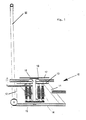
- a therapy device with a rotatable System consisting of a support surface (15) and one centrally and rigidly arranged on the surface Support column (16), which in turn at its upper end rigidly connected to said platform (17).
- Fig. 1 is a support frame 10 with supports 11 and 12 and a carrier 13 recognizable, on which at least three pendulums 14 a support surface 15 is suspended, in its center of area carries a rigidly connected to her support column 16, the again at its upper end a rigid with the mentioned Support column 16 connected platform 17 carries.
- the rotational movement of the platform 17th basically also a translational movement superimposed be. Unless the translatory movement is desired is, this can by a support column 16 encompassing suitable guide 18 narrowed or, if necessary. Also complete be prevented.
- the person to be treated presents himself with one or more with both feet on the platform 17. Stimulated by impulses The platform is turned into a limited in its extent, rotational Pendulum movement offset. The person to be treated must now try their posture to the movements of Adapt platform 17. This will be numerous nerve and Muscle areas put into action during the usual Movements are not used. This applies in particular to muscles of sensomotor function of the pelvis and lumbar region, is desirable and leads to many areas Musculature to therapeutic stimuli and thus to desired and, if necessary, necessary training effects.
- External rotation resistors - e.g. from a roller cable or Theraband starting - can be easily on transfer the therapy level. It's also a rotatory one Training for the muscle popliteus within a closed kinetic chain possible. The equilibrium reaction occurs mainly in the limb and the trunk muscles.
- another Platform can be arranged around one of their diameters around a limited tilting movement allows.
- the upper ankle actively in the equilibrium reaction involved.
- the rotation can also from the outside, for example via a Roller cable, easily transferred to the therapy level become.
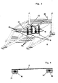
- FIG. 2 shows a plan view of a therapy device according to the invention.
- FIG. 2 It can be seen that for the pendulum 14 suspension points 19 and 19a with different radii, i. With different distances to the center of the platform 17th or the support surface 15 can be selected, resulting in to change the dynamic behavior of platform 17. Even if in Fig. 2 only suspension points 19, 19a with two different radii (distances to the center) shown are, of course, suspension points 19, 19a are provided on further radii.
- the respective rotational deflection of the platform 17 can over a display arm 20 connected to it for the trainee and whose therapists are made visible. If necessary. can the maximum rotational deflections of the platform 17 also through Stops 21 are limited to the display arm 20. This is especially in the first training phase often required.
- Figs. 1 and 2 are described in the Fig. 3 again clarifies.
- the pendulum Suspended 14 carrying the support surface 15.
- the support surface 15 is rigid with the support surface 15th connected support column 16, which in turn - as out 1 recognizable - the rigidly connected to her platform 17th wearing.
- the suspension points 19, 19a of the platform 17 also has the support surface 15 associated suspension points 19, 19a on.
- the sensitivity of the suspension can also be influenced by the fact that the pendulum 14 between the Suspension points 19 of the platform 17 with larger radius and the suspension points 19a with a smaller radius of the support surface 15 or vice versa.
- the desired rotational movement of the platform 17 also about a storage of the platform 17 via between Kugelkalotten arranged ball can be achieved.
- the corresponding design of the spherical caps has the platform 17 the tendency to return to their original position.
- the behavior of such an arrangement is similar as in a pendulum arrangement, wherein the Reibkraftgire in a pendulum arrangement, however, considerably lower and thus cheaper.
- Pendulums 15 have those according to EP 0 259 325 B1 as proved particularly advantageous. But it can also be usual Rope pendulum made of textile or plastic materials or from braided steel wire are used.
- Multiple platforms may be at the same height or different Heights are arranged side by side, so that the user is moving in one plane or on can train a simulated staircase. This results rotationally a two-sided knee load.
- the rotation can also motorized by a cam drive, via magnetic forces or manually stimulated rhythmically by the therapist.
- the Pendulums may also be made of textile or plastic materials consist.
- the support column 16 can from one of the translational movements Surrounding restricting or preventing guide 18 be.
- the high-frequency oscillation of the therapy level triggers efferent Impulses of enormous irritation density at the stabilizing musculature out.
- the stimulus response of the muscles is practically in the whole body metrologically as rhythmic stabilization detectable. The result is a coordinative training effect of considerable effectiveness, without complicated exercise instructions necessary.
- the therapy device very well suited.
Landscapes
- Health & Medical Sciences (AREA)
- Cardiology (AREA)
- Vascular Medicine (AREA)
- General Health & Medical Sciences (AREA)
- Physical Education & Sports Medicine (AREA)
- Rehabilitation Tools (AREA)
- Radiation-Therapy Devices (AREA)
- Percussion Or Vibration Massage (AREA)
Abstract
Description
- Fig. 1
- ein Gestell mit einer rotationsfähigen Plattform, die über eine Stützsäule starr mit einer Stützplatte verbunden ist, die ihrerseits über Pendel an einem Gestell aufgehängt ist,
- Fig. 2
- eine Draufsicht auf ein solches Gestell,
- Fig. 3
- eine perspektivische Sicht auf die Unterseite des Gestells, wobei Teile des Gestell weggebrochen sind, um die Stützplatte und ihre Aufhängung besser veranschaulichen zu können sowie
- Fig. 4
- eine Lagerung der Plattform auf zwischen Kugelkalotten angeordneten Kugeln.
Claims (14)
- Therapiegerät mit schwingungsfähiger Plattform und einer an mindestens drei Pendeln aufgehängten Stützfläche, dadurch gekennzeichnet, dass ein rotationsfähiges System vorhanden ist, dass aus einer Stützfläche (15) und einer mittig und starr auf ihrer Oberfläche mit ihr verbundenen Stützsäule (16) besteht, die ihrerseits an ihrem oberen Ende starr mit einer zuvor erwähnten rotationsfähigen Plattform (17) verbunden ist.
- Therapiegerät nach Anspruch 1, dadurch gekennzeichnet, dass vier Pendel (14) vorhanden sind.
- Therapiegerät, nach einem der Ansprüche 1 oder 2, dadurch gekennzeichnet, dass die Pendel aus Textil- oder Kunststoffmaterialien bestehen.
- Therapiegerät, nach einem der Ansprüche 1 oder 2, dadurch gekennzeichnet, daß die Pendel aus geflochtenem Stahldraht bestehen.
- Therapiegerät nach einem der Ansprüche 1 bis 4, dadurch gekennzeichnet, dass ein Gegenpendel vorhanden ist.
- Therapiegerät nach einem der Ansprüche 1 bis 5, dadurch gekennzeichnet, dass die Stützsäule (16) von einer die translatorischen Bewegungungen einengenden bzw. verhindernden Führung (18) umgeben ist.
- Therapiegerät nach einem der Ansprüche 1 bis 6, dadurch gekennzeichnet, dass verschiedene, einander zugeordnete Gruppen von Aufhängepunkten (19, 19a) auf unterschiedlichen Radien der Stützfläche (15) und der Plattform (17) angeordnet sind.
- Therapiegerät nach einem der Ansprüche 1 bis 7, dadurch gekennzeichnet, dass ein die jeweilige rotatorische Positionierung der Plattform (17) veranschaulichender Anzeigearm (20) vorhanden ist.
- Therapiergät nach einem der Ansprüche 1 bis 8, dadurch gekennzeichnet, dass die rotatorische Bewegung der Plattform (17) begrenzende Anschläge (21) vorhanden sind.
- Therapiegerät nach Anspruch 9, dadurch gekennzeichnet, dass die Anschläge verstellbar sind.
- Therapiegerät nach einem der Ansprüche 1 bis 10, dadurch gekennzeichnet, dass mehrere Plattformen (17) nebeneinander angeordnet sind.
- Therapiegerät nach Anspruch 11, dadurch gekennzeichnet, dass die Plattformen (17) in gleicher Höhe nebeneinander angeordnet sind.
- Therapiegerät nach einem der Ansprüche 11 oder 12, dadurch gekennzeichnet, dass mehrere Plattformen (17) in unterschiedlicher Höhe stufenförmig nebeneinander angeordnet sind.
- Therapiegerät nach einem der Ansprüche 1 bis 13, dadurch gekennzeichnet, dass ein etwa bis zur Hüfthöhe des Patienten reichender Haltegriff (22) vorhanden ist.
Applications Claiming Priority (2)
| Application Number | Priority Date | Filing Date | Title |
|---|---|---|---|
| DE10354246 | 2003-11-18 | ||
| DE10354246A DE10354246A1 (de) | 2003-11-18 | 2003-11-18 | Kinetisches Therapiegerät mit rotationsfähiger Plattform |
Publications (2)
| Publication Number | Publication Date |
|---|---|
| EP1533005A1 true EP1533005A1 (de) | 2005-05-25 |
| EP1533005B1 EP1533005B1 (de) | 2008-07-30 |
Family
ID=34428829
Family Applications (1)
| Application Number | Title | Priority Date | Filing Date |
|---|---|---|---|
| EP04090455A Expired - Lifetime EP1533005B1 (de) | 2003-11-18 | 2004-11-18 | Kinetisches Therapiegerät mit schwingungsfähiger Plattform |
Country Status (3)
| Country | Link |
|---|---|
| EP (1) | EP1533005B1 (de) |
| AT (1) | ATE402745T1 (de) |
| DE (2) | DE10354246A1 (de) |
Families Citing this family (1)
| Publication number | Priority date | Publication date | Assignee | Title |
|---|---|---|---|---|
| EP3400988B1 (de) | 2017-05-09 | 2021-09-29 | Werner Stark | Sensomotorisches trainings- und therapiegerät |
Citations (4)
| Publication number | Priority date | Publication date | Assignee | Title |
|---|---|---|---|---|
| US4220329A (en) * | 1977-12-16 | 1980-09-02 | Agyagos Ferenc I | Exerciser device |
| EP0259325B1 (de) * | 1985-05-14 | 1990-01-03 | Eduard Haider | Pendel |
| FR2654942A1 (fr) * | 1989-11-24 | 1991-05-31 | Tardieu Jacques | Dispositif de reeducation proprioceptive et d'entrainement sportif par appui podal et suivant plusieurs degres de liberte de mouvements. |
| DE29713930U1 (de) * | 1997-08-05 | 1997-10-30 | Dr. Brügger-Institut GmbH, Zürich | Trainingsgerät |
Family Cites Families (4)
| Publication number | Priority date | Publication date | Assignee | Title |
|---|---|---|---|---|
| DE3229934C2 (de) * | 1982-08-09 | 1986-10-30 | Eduard 8591 Pullenreuth Haider | Sitz- oder Ruhemöbel mit pendelnd aufgehängter Sitz- bzw. Ruhefläche |
| JPH0614967A (ja) * | 1992-07-02 | 1994-01-25 | Ebara Corp | 回転テーブル装置 |
| DE29503801U1 (de) * | 1995-02-24 | 1995-04-27 | Haidermetall Eduard Haider KG, 95704 Pullenreuth | Schwingfähiger Stehboden |
| DE20218959U1 (de) * | 2002-12-06 | 2003-03-06 | Chuang, Jin Chen, Fong Yuan, Taichung | Trimmgerät für Step- und Schwingübungen |
-
2003
- 2003-11-18 DE DE10354246A patent/DE10354246A1/de not_active Withdrawn
-
2004
- 2004-11-18 DE DE502004007722T patent/DE502004007722D1/de not_active Expired - Lifetime
- 2004-11-18 AT AT04090455T patent/ATE402745T1/de active
- 2004-11-18 EP EP04090455A patent/EP1533005B1/de not_active Expired - Lifetime
Patent Citations (4)
| Publication number | Priority date | Publication date | Assignee | Title |
|---|---|---|---|---|
| US4220329A (en) * | 1977-12-16 | 1980-09-02 | Agyagos Ferenc I | Exerciser device |
| EP0259325B1 (de) * | 1985-05-14 | 1990-01-03 | Eduard Haider | Pendel |
| FR2654942A1 (fr) * | 1989-11-24 | 1991-05-31 | Tardieu Jacques | Dispositif de reeducation proprioceptive et d'entrainement sportif par appui podal et suivant plusieurs degres de liberte de mouvements. |
| DE29713930U1 (de) * | 1997-08-05 | 1997-10-30 | Dr. Brügger-Institut GmbH, Zürich | Trainingsgerät |
Also Published As
| Publication number | Publication date |
|---|---|
| DE502004007722D1 (de) | 2008-09-11 |
| ATE402745T1 (de) | 2008-08-15 |
| EP1533005B1 (de) | 2008-07-30 |
| DE10354246A1 (de) | 2005-07-07 |
Similar Documents
| Publication | Publication Date | Title |
|---|---|---|
| DE3030679C2 (de) | ||
| EP0810834B1 (de) | Schwingfähiger stehboden | |
| DE8530304U1 (de) | Durch elektromechanischen Antrieb kippbares Bett | |
| DE2519614A1 (de) | Streck- und gymnastiktisch | |
| AT407118B (de) | Sportgerät | |
| EP1541112B1 (de) | Muskelstimulations- und Massagegerät | |
| EP0121902A1 (de) | Gymnastikgerät | |
| EP1292366B1 (de) | Vorrichtung zur therapie und zum trainieren der gelenke des menschlichen körpers | |
| DE102008055885B4 (de) | Vorrichtung zur therapeutischen Behandlung der Wirbelsäulengelenke und/oder der Wirbelsäulenmuskulatur | |
| EP1533005B1 (de) | Kinetisches Therapiegerät mit schwingungsfähiger Plattform | |
| EP4271487B1 (de) | Laufbandanordnung mit beweglichen stützelementen | |
| WO2006030007A1 (de) | Gerät zur selektiven stimulation bestimmter körperpartien | |
| EP1955735B1 (de) | Trampolin | |
| EP2082786B1 (de) | Vorrichtung zum Trainieren koordinativer Fähigkeiten und der wirbelsäulenstabilisierenden Muskulatur des menschlichen Körpers | |
| DE102004027524B4 (de) | Multifunktionales Trainingsgerät zur Stärkung der Bein- und Rückenmuskulatur | |
| DE20317943U1 (de) | Kinetisches Therapiegerät mit rotationsfähiger Plattform | |
| DE19540872C2 (de) | Atmungssensitive Gesundheitsliege | |
| DE19504056A1 (de) | Trainingsgerät | |
| WO1991000126A1 (de) | Trainingsapparatur zur therapeutischen behandlung | |
| DE102020129533A1 (de) | Therapeutische Sitzvorrichtung | |
| DE102004008899B3 (de) | Trainingsgerät | |
| DE3304005C2 (de) | Gerät zur dosierbaren Streckung des menschlichen Körpers | |
| EP3970811A1 (de) | Trainingsgerät zum trainieren einzelner muskelgruppen im oberkörper | |
| DE9200725U1 (de) | Therapie-/Trainingsgerät | |
| DE8019321U1 (de) | Trainingsgerät |
Legal Events
| Date | Code | Title | Description |
|---|---|---|---|
| PUAI | Public reference made under article 153(3) epc to a published international application that has entered the european phase |
Free format text: ORIGINAL CODE: 0009012 |
|
| AK | Designated contracting states |
Kind code of ref document: A1 Designated state(s): AT BE BG CH CY CZ DE DK EE ES FI FR GB GR HU IE IS IT LI LU MC NL PL PT RO SE SI SK TR |
|
| AX | Request for extension of the european patent |
Extension state: AL HR LT LV MK YU |
|
| 17P | Request for examination filed |
Effective date: 20051125 |
|
| AKX | Designation fees paid |
Designated state(s): AT BE BG CH CY CZ DE DK EE ES FI FR GB GR HU IE IS IT LI LU MC NL PL PT RO SE SI SK TR |
|
| 17Q | First examination report despatched |
Effective date: 20061121 |
|
| RAP1 | Party data changed (applicant data changed or rights of an application transferred) |
Owner name: HAIDERMETALL EDUARD HAIDER GMBH & CO. KG |
|
| RIN1 | Information on inventor provided before grant (corrected) |
Inventor name: HAIDER, EDUARD |
|
| GRAP | Despatch of communication of intention to grant a patent |
Free format text: ORIGINAL CODE: EPIDOSNIGR1 |
|
| GRAS | Grant fee paid |
Free format text: ORIGINAL CODE: EPIDOSNIGR3 |
|
| GRAA | (expected) grant |
Free format text: ORIGINAL CODE: 0009210 |
|
| AK | Designated contracting states |
Kind code of ref document: B1 Designated state(s): AT BE BG CH CY CZ DE DK EE ES FI FR GB GR HU IE IS IT LI LU MC NL PL PT RO SE SI SK TR |
|
| REG | Reference to a national code |
Ref country code: GB Ref legal event code: FG4D Free format text: NOT ENGLISH |
|
| REG | Reference to a national code |
Ref country code: CH Ref legal event code: EP |
|
| REF | Corresponds to: |
Ref document number: 502004007722 Country of ref document: DE Date of ref document: 20080911 Kind code of ref document: P |
|
| REG | Reference to a national code |
Ref country code: IE Ref legal event code: FG4D Free format text: LANGUAGE OF EP DOCUMENT: GERMAN |
|
| PG25 | Lapsed in a contracting state [announced via postgrant information from national office to epo] |
Ref country code: PT Free format text: LAPSE BECAUSE OF FAILURE TO SUBMIT A TRANSLATION OF THE DESCRIPTION OR TO PAY THE FEE WITHIN THE PRESCRIBED TIME-LIMIT Effective date: 20081230 Ref country code: NL Free format text: LAPSE BECAUSE OF FAILURE TO SUBMIT A TRANSLATION OF THE DESCRIPTION OR TO PAY THE FEE WITHIN THE PRESCRIBED TIME-LIMIT Effective date: 20080730 Ref country code: IS Free format text: LAPSE BECAUSE OF FAILURE TO SUBMIT A TRANSLATION OF THE DESCRIPTION OR TO PAY THE FEE WITHIN THE PRESCRIBED TIME-LIMIT Effective date: 20081130 Ref country code: ES Free format text: LAPSE BECAUSE OF FAILURE TO SUBMIT A TRANSLATION OF THE DESCRIPTION OR TO PAY THE FEE WITHIN THE PRESCRIBED TIME-LIMIT Effective date: 20081110 |
|
| PG25 | Lapsed in a contracting state [announced via postgrant information from national office to epo] |
Ref country code: BG Free format text: LAPSE BECAUSE OF FAILURE TO SUBMIT A TRANSLATION OF THE DESCRIPTION OR TO PAY THE FEE WITHIN THE PRESCRIBED TIME-LIMIT Effective date: 20081030 Ref country code: SI Free format text: LAPSE BECAUSE OF FAILURE TO SUBMIT A TRANSLATION OF THE DESCRIPTION OR TO PAY THE FEE WITHIN THE PRESCRIBED TIME-LIMIT Effective date: 20080730 Ref country code: FI Free format text: LAPSE BECAUSE OF FAILURE TO SUBMIT A TRANSLATION OF THE DESCRIPTION OR TO PAY THE FEE WITHIN THE PRESCRIBED TIME-LIMIT Effective date: 20080730 |
|
| REG | Reference to a national code |
Ref country code: IE Ref legal event code: FD4D |
|
| PG25 | Lapsed in a contracting state [announced via postgrant information from national office to epo] |
Ref country code: DK Free format text: LAPSE BECAUSE OF FAILURE TO SUBMIT A TRANSLATION OF THE DESCRIPTION OR TO PAY THE FEE WITHIN THE PRESCRIBED TIME-LIMIT Effective date: 20080730 Ref country code: EE Free format text: LAPSE BECAUSE OF FAILURE TO SUBMIT A TRANSLATION OF THE DESCRIPTION OR TO PAY THE FEE WITHIN THE PRESCRIBED TIME-LIMIT Effective date: 20080730 Ref country code: IE Free format text: LAPSE BECAUSE OF FAILURE TO SUBMIT A TRANSLATION OF THE DESCRIPTION OR TO PAY THE FEE WITHIN THE PRESCRIBED TIME-LIMIT Effective date: 20080730 |
|
| PG25 | Lapsed in a contracting state [announced via postgrant information from national office to epo] |
Ref country code: RO Free format text: LAPSE BECAUSE OF FAILURE TO SUBMIT A TRANSLATION OF THE DESCRIPTION OR TO PAY THE FEE WITHIN THE PRESCRIBED TIME-LIMIT Effective date: 20080730 Ref country code: CZ Free format text: LAPSE BECAUSE OF FAILURE TO SUBMIT A TRANSLATION OF THE DESCRIPTION OR TO PAY THE FEE WITHIN THE PRESCRIBED TIME-LIMIT Effective date: 20080730 Ref country code: SK Free format text: LAPSE BECAUSE OF FAILURE TO SUBMIT A TRANSLATION OF THE DESCRIPTION OR TO PAY THE FEE WITHIN THE PRESCRIBED TIME-LIMIT Effective date: 20080730 |
|
| BERE | Be: lapsed |
Owner name: HAIDERMETALL EDUARD HAIDER G.M.B.H. & CO. KG Effective date: 20081130 |
|
| PLBE | No opposition filed within time limit |
Free format text: ORIGINAL CODE: 0009261 |
|
| STAA | Information on the status of an ep patent application or granted ep patent |
Free format text: STATUS: NO OPPOSITION FILED WITHIN TIME LIMIT |
|
| PG25 | Lapsed in a contracting state [announced via postgrant information from national office to epo] |
Ref country code: MC Free format text: LAPSE BECAUSE OF NON-PAYMENT OF DUE FEES Effective date: 20081130 |
|
| 26N | No opposition filed |
Effective date: 20090506 |
|
| GBPC | Gb: european patent ceased through non-payment of renewal fee |
Effective date: 20081118 |
|
| PG25 | Lapsed in a contracting state [announced via postgrant information from national office to epo] |
Ref country code: IT Free format text: LAPSE BECAUSE OF FAILURE TO SUBMIT A TRANSLATION OF THE DESCRIPTION OR TO PAY THE FEE WITHIN THE PRESCRIBED TIME-LIMIT Effective date: 20080730 |
|
| PG25 | Lapsed in a contracting state [announced via postgrant information from national office to epo] |
Ref country code: BE Free format text: LAPSE BECAUSE OF NON-PAYMENT OF DUE FEES Effective date: 20081130 |
|
| PG25 | Lapsed in a contracting state [announced via postgrant information from national office to epo] |
Ref country code: GB Free format text: LAPSE BECAUSE OF NON-PAYMENT OF DUE FEES Effective date: 20081118 |
|
| PG25 | Lapsed in a contracting state [announced via postgrant information from national office to epo] |
Ref country code: SE Free format text: LAPSE BECAUSE OF FAILURE TO SUBMIT A TRANSLATION OF THE DESCRIPTION OR TO PAY THE FEE WITHIN THE PRESCRIBED TIME-LIMIT Effective date: 20081030 |
|
| PG25 | Lapsed in a contracting state [announced via postgrant information from national office to epo] |
Ref country code: PL Free format text: LAPSE BECAUSE OF FAILURE TO SUBMIT A TRANSLATION OF THE DESCRIPTION OR TO PAY THE FEE WITHIN THE PRESCRIBED TIME-LIMIT Effective date: 20080730 |
|
| PG25 | Lapsed in a contracting state [announced via postgrant information from national office to epo] |
Ref country code: HU Free format text: LAPSE BECAUSE OF FAILURE TO SUBMIT A TRANSLATION OF THE DESCRIPTION OR TO PAY THE FEE WITHIN THE PRESCRIBED TIME-LIMIT Effective date: 20090131 Ref country code: CY Free format text: LAPSE BECAUSE OF FAILURE TO SUBMIT A TRANSLATION OF THE DESCRIPTION OR TO PAY THE FEE WITHIN THE PRESCRIBED TIME-LIMIT Effective date: 20080730 Ref country code: LU Free format text: LAPSE BECAUSE OF NON-PAYMENT OF DUE FEES Effective date: 20081118 |
|
| PG25 | Lapsed in a contracting state [announced via postgrant information from national office to epo] |
Ref country code: TR Free format text: LAPSE BECAUSE OF FAILURE TO SUBMIT A TRANSLATION OF THE DESCRIPTION OR TO PAY THE FEE WITHIN THE PRESCRIBED TIME-LIMIT Effective date: 20080730 |
|
| PG25 | Lapsed in a contracting state [announced via postgrant information from national office to epo] |
Ref country code: GR Free format text: LAPSE BECAUSE OF FAILURE TO SUBMIT A TRANSLATION OF THE DESCRIPTION OR TO PAY THE FEE WITHIN THE PRESCRIBED TIME-LIMIT Effective date: 20081031 |
|
| REG | Reference to a national code |
Ref country code: FR Ref legal event code: PLFP Year of fee payment: 12 |
|
| REG | Reference to a national code |
Ref country code: FR Ref legal event code: PLFP Year of fee payment: 13 |
|
| REG | Reference to a national code |
Ref country code: FR Ref legal event code: PLFP Year of fee payment: 14 |
|
| PGFP | Annual fee paid to national office [announced via postgrant information from national office to epo] |
Ref country code: AT Payment date: 20181024 Year of fee payment: 15 |
|
| PGFP | Annual fee paid to national office [announced via postgrant information from national office to epo] |
Ref country code: CH Payment date: 20181019 Year of fee payment: 15 Ref country code: FR Payment date: 20181127 Year of fee payment: 15 |
|
| PGFP | Annual fee paid to national office [announced via postgrant information from national office to epo] |
Ref country code: DE Payment date: 20190124 Year of fee payment: 15 |
|
| REG | Reference to a national code |
Ref country code: DE Ref legal event code: R119 Ref document number: 502004007722 Country of ref document: DE |
|
| REG | Reference to a national code |
Ref country code: CH Ref legal event code: PL |
|
| PG25 | Lapsed in a contracting state [announced via postgrant information from national office to epo] |
Ref country code: LI Free format text: LAPSE BECAUSE OF NON-PAYMENT OF DUE FEES Effective date: 20191130 Ref country code: CH Free format text: LAPSE BECAUSE OF NON-PAYMENT OF DUE FEES Effective date: 20191130 |
|
| REG | Reference to a national code |
Ref country code: AT Ref legal event code: MM01 Ref document number: 402745 Country of ref document: AT Kind code of ref document: T Effective date: 20191118 |
|
| PG25 | Lapsed in a contracting state [announced via postgrant information from national office to epo] |
Ref country code: DE Free format text: LAPSE BECAUSE OF NON-PAYMENT OF DUE FEES Effective date: 20200603 Ref country code: FR Free format text: LAPSE BECAUSE OF NON-PAYMENT OF DUE FEES Effective date: 20191130 |
|
| PG25 | Lapsed in a contracting state [announced via postgrant information from national office to epo] |
Ref country code: AT Free format text: LAPSE BECAUSE OF NON-PAYMENT OF DUE FEES Effective date: 20191118 |