EP1531139A1 - Maschinenrahmenlose Antriebseinheit für einen Aufzug - Google Patents
Maschinenrahmenlose Antriebseinheit für einen Aufzug Download PDFInfo
- Publication number
- EP1531139A1 EP1531139A1 EP04026113A EP04026113A EP1531139A1 EP 1531139 A1 EP1531139 A1 EP 1531139A1 EP 04026113 A EP04026113 A EP 04026113A EP 04026113 A EP04026113 A EP 04026113A EP 1531139 A1 EP1531139 A1 EP 1531139A1
- Authority
- EP
- European Patent Office
- Prior art keywords
- motor
- brake
- bearing
- drive unit
- unit according
- Prior art date
- Legal status (The legal status is an assumption and is not a legal conclusion. Google has not performed a legal analysis and makes no representation as to the accuracy of the status listed.)
- Granted
Links
- 230000006835 compression Effects 0.000 claims description 5
- 238000007906 compression Methods 0.000 claims description 5
- 238000009423 ventilation Methods 0.000 claims description 2
- 238000010276 construction Methods 0.000 description 3
- 238000012423 maintenance Methods 0.000 description 1
- 238000004519 manufacturing process Methods 0.000 description 1
- 230000000149 penetrating effect Effects 0.000 description 1
- 125000006850 spacer group Chemical group 0.000 description 1
Images



Classifications
-
- B—PERFORMING OPERATIONS; TRANSPORTING
- B66—HOISTING; LIFTING; HAULING
- B66B—ELEVATORS; ESCALATORS OR MOVING WALKWAYS
- B66B11/00—Main component parts of lifts in, or associated with, buildings or other structures
- B66B11/04—Driving gear ; Details thereof, e.g. seals
-
- B—PERFORMING OPERATIONS; TRANSPORTING
- B66—HOISTING; LIFTING; HAULING
- B66B—ELEVATORS; ESCALATORS OR MOVING WALKWAYS
- B66B11/00—Main component parts of lifts in, or associated with, buildings or other structures
- B66B11/04—Driving gear ; Details thereof, e.g. seals
- B66B11/043—Driving gear ; Details thereof, e.g. seals actuated by rotating motor; Details, e.g. ventilation
Definitions
- the invention relates to a machine frame Drive unit for a lift consisting of at least a motor, at least one brake and one between Bearing plates arranged traction sheave, the engine is arranged on a bearing plate.
- a drive unit is in the essentially from an electric motor, a motor stand, a bearing block, a traction sheave and a Machine frame with counter roller attachment known.
- Stator of the electric motor is by means of a flange with screwed to the engine stand.
- the rotor of the electric motor sits on a free end of a traction sheave bearing shaft, the bearing block and the engine mount is stored.
- the traction sheave is by means of the shaft on Motor stand and mounted on the bearing block.
- a brake is in inner area of the engine stand and arranged with a Covering covered.
- a disadvantage of the known device is that the brake is arranged inside. For the maintenance the brake parts are difficult to access.
- Next disadvantage is the bearing block and the motor stand supporting Machine frame, which makes the construction cumbersome and the entire drive unit more expensive.
- the invention aims to remedy this situation.
- the invention, as characterized in claim 1 solves the task to avoid the disadvantages of the known device and to create an elevator drive with brake in each Case works reliably and is simple.
- the advantages achieved by the invention are in Essential to see that a drive unit with short wave and thus a small length of the Drive unit is realized. It is also advantageous that the brake release cylinder and supply lines of the Brake disc are arranged separately. In case of Leakage or breakage can cause the braking surfaces do not oil. Brake readiness remains guaranteed.
- Next advantageous is that with the machine frame-less construction of the drive unit more Freedom for the rope guide between the traction sheave and the counter role exists. There are bigger ones Rope spacing feasible.
- the for large elevator cabins and for high production and for high Driving speeds designed drive unit has For example, a height of more than two meters and a total weight of more than ten tons, with the machine frame-less construction weight and cost can be saved.
- FIG. 1 shows the completely assembled drive unit 1, essentially consisting of a motor 2A, as Stock plate serving motor stand 3, one as a bearing plate serving bearing block 4, a traction sheave 5 and a Counter roller attachment 6.
- the stator 2.1 of the electric motor 2A is arranged on the motor stand 3.
- the rotor 2.2 of the Electric motor 2A sits on a free end of a Traction sheave 5 supporting shaft 15, the bearing block 4 and is mounted on the motor stand 3.
- the free end of the shaft projects beyond the motor stand 3.
- the traction sheave 5 is by means of the shaft mounted on the motor stand 3 and the bearing block 4. ever Side is a brake 7 on the bearing block 4 is arranged.
- Webs 8.9 connect the motor stand 3 with the bearing block 4, for example, an upper web 8 and one side lateral web 9 are provided.
- Motor stand 3, Bearing 4 and the webs 8.9 form a stable framework, without a motor stand 3 and bearing block 4 supporting Machine frame is necessary.
- Motor stand 3 and bearing block 4 are by means of supporting elements 10 on a boom 3.1 or on a boom 4.1 machine frame on each one Base 11 or carrier stored.
- the counter roller attachment 6 consisting of side plates 12 and counter-roller 13 right on Motor stand 3 and arranged on the bearing block 4.
- One Hydraulic unit 14 serves to supply the actuator of Brake 7. The actuator can also be operated electrically become.
- Supporting cables 25 form the rope strand, on the one hand of the Traction sheave 5 on the counter-roller 13 and on the other hand of the traction sheave 5 is guided directly into the elevator shaft are.
- the wire rope distance is by means of Counter roll cultivation 6 adjustable, with the side plates 12 at holes 12.1 with the motor stand 3 and with the Bearing 4 are screwed.
- Fig. 2 shows the motor stand 3 with traction sheave 5, the lateral webs 9 and the upper web 8.
- the bearing block 4 is shown in FIG.
- a traction sheave 5 carrying Shaft 15 is at one end on the engine stand 3 and at the other end on Bearing 4 stored.
- the bearing block side bearing is 16 designated.
- At the traction sheave 5 is a brake disc 17th arranged with ring gear 18, over which the traction sheave 5 in Evacuation operation is drivable.
- Fig. 3 shows an interior view of the bearing block 4 with Bearing housing 19 for receiving the bearing 16.
- Eyelets 20 visible on which the brake 7 is mounted.
- the Support surface for the upper bridge 8 is 21 and the Aufläge vom for the lateral webs 9 are 22 designated, wherein the webs 8.9 with the bearing block 4 or can be screwed with the motor stand 3, for example.
- the evacuation drive consists of a motor 23 with pinion 24, wherein in evacuation operation, the pinion 24 in the Sprocket 18 engages and the traction sheave 5 in motion added.
- Fig. 4 shows the upper web 8, the box-shaped is formed and the bearing surface 8.1 on the Support surface 21 fits.
- Fig. 5 shows the lateral web 9, the wedge-shaped is formed and the bearing surface 9.1 on the Support surface 22 fits.
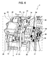
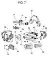
- Fig. 6 and Fig. 7 show the bearing block 4 on each side arranged brake 7 of the drive unit 1, wherein a Brake caliper 30 to the eyelets 20 penetrating axes 31st is floating.
- the caliper 30 may be at the most adjustable by means of adjusting screws 32 Move distance d, wherein each axis 31 a spring 33rd provided, the caliper 30 in the direction of traction sheave 5 charged.
- the axes 31 are at one with the Bearing 4 related support bracket 34 fixed.
- the caliper 30 carries the drive pulley side, inner brake shoe 40 and serves as Support for spacer tubes 35 and threaded rods 36, the a support plate 37 for a hydraulic, for example Hold actuator 38.
- Compression springs 39 is supported at one end to the support plate 37 and at the other end to a Pressure plate 41 from which guided by means of the caliper 30 Bolt 42 the spring force of the compression springs 39 on the outside Transfer brake shoe 43.
- Bolt 42 the spring force of the compression springs 39 on the outside Transfer brake shoe 43.
- the activated actuator 38 acts the activated actuator 38 by means of a pull rod 44 the pressure plate 41 and raises the spring force of the coaxial Pull rod 44 arranged compression springs 39 on the outer Brake shoe 43 on.
- the caliper 30 moves due to the spring force of the spring 33 in the direction Traction sheave 5, wherein the inner brake shoe 40 of the Brake disc 17 is moved away.
- a sensor 45 is provided to monitor the Braking condition.
- FIG. 8 shows the completely assembled drive unit 1 with two motors, essentially consisting of a motor 2A and a motor 2B, serving as a bearing plate Motor stand 3, a bearing block serving as end shield 4, a traction sheave 5 and a Gegenrollenanbau 6. Die the traction sheave 5 bearing, on the bearing plates 3.4 mounted shaft 15 has two free ends, wherein the a free end of the rotor of the one motor 2A and on other free end of the rotor of the other motor 2B is arranged.
- Webs 8.9 connect the motor stand 3 with the bearing block 4, for example, an upper web 8 and one side lateral web 9 are provided.
- Motor stand 3, Bearing 4 and the webs 8.9 form a stable framework, without a motor stand 3 and bearing block 4 supporting Machine frame is necessary.
Landscapes
- Engineering & Computer Science (AREA)
- Civil Engineering (AREA)
- Mechanical Engineering (AREA)
- Structural Engineering (AREA)
- Cage And Drive Apparatuses For Elevators (AREA)
- Connection Of Motors, Electrical Generators, Mechanical Devices, And The Like (AREA)
- Braking Arrangements (AREA)
Abstract
Description
eine erfindungsgemässe Antriebseinheit mit einem Motor,
einen Motorständer mit Treibscheibe und Stegen,
einen Lagerbock mit Lagergehäuse und Treibscheibe,
einen oberen Steg,
einen seitlichen Steg,
Einzelheiten einer Bremse und
eine erfindungsgemässe Antriebseinheit mit zwei Motoren.
Claims (7)
- Maschinenrahmenlose Antriebseinheit (1) für einen Aufzug bestehend aus mindestens einem Motor (2A,2B), mindestens einer Bremse (7) und einer zwischen Lagerschildern (3,4) angeordneten Treibscheibe (5), wobei der Motor (2A,2B) an einem Lagerschild (3,4) angeordnet ist und jedes Lagerschild (3,4) von einem Sockel (11) getragen ist.
- Antriebseinheit nach Anspruch 1,
dadurch gekennzeichnet, dass die Lagerschilder (3,4) mittels Stegen (8,9) verbunden sind. - Antriebseinheit nach einem der Ansprüchen 1 oder 2,
dadurch gekennzeichnet, dass die Treibscheibe (5) von einer Welle (15) getragen ist, die an einem als Lagerschild dienenden Motorständer (3) und an einem als Lagerschild dienenden Lagerbock (4) gelagert ist, wobei der Motor (2A,2B) am Motorständer (3) bzw. am Lagerbock (4) angeordnet ist und der Rotor des Motors (2A,2B) von einem freien Ende der Welle (15) getragen ist. - Antriebseinheit nach Anspruch 3
dadurch gekennzeichnet, dass an den Lagerschildern (3,4) ein Gegenrollenanbau (6) anbringbar ist, der unterschiedliche Seilstrangabstände ermöglicht. - Antriebseinheit nach Anspruch 3,
dadurch gekennzeichnet, dass an der Treibscheibe (5) eine Bremsscheibe (17) mit Zahnkranz (18) angeordnet ist, in den bei Evakuierbetrieb ein Zahnritzel (24) eines Evakuiermotors (23) eingreift. - Antriebseinheit nach einem der vorhergehenden Ansprüche,
dadurch gekennzeichnet, dass mindestens am einen Lagerschild (4) mindestens eine Bremse (7) angeordnet ist, die mittels Bremsbacken (40,43) auf die Bremsscheibe (17) einwirkt. - Antriebseinheit nach Anspruch 6,
dadurch gekennzeichnet, dass die Bremse (7) einen schwimmend gelagerten Bremssattel (30) aufweist, der die eine Bremsbacke (40) trägt und an dem eine einen Aktuator (38) tragende Trägerplatte (37) abgestützt ist, wobei sich Druckfedern (39) einenends an der Trägerplatte (37) und anderenends an einer Druckplatte (41) abstützen, wobei die Druckplatte (41) mittels vom Bremssattel (30) geführten Bolzen (42) die Federkraft der Druckfedern (39) auf die andere Bremsbacke (43) übertragen und zur Lüftung der Bremse (7) der aktivierte Aktuator (38) mittels einer Zugstange (44) auf die Druckplatte (41) einwirkt und die Federkraft auf die andere Bremsbacke (43) aufhebt.
Priority Applications (1)
| Application Number | Priority Date | Filing Date | Title |
|---|---|---|---|
| EP04026113.3A EP1531139B1 (de) | 2003-11-13 | 2004-11-04 | Maschinenrahmenlose Antriebseinheit für einen Aufzug |
Applications Claiming Priority (3)
| Application Number | Priority Date | Filing Date | Title |
|---|---|---|---|
| EP03405807 | 2003-11-13 | ||
| EP03405807 | 2003-11-13 | ||
| EP04026113.3A EP1531139B1 (de) | 2003-11-13 | 2004-11-04 | Maschinenrahmenlose Antriebseinheit für einen Aufzug |
Publications (2)
| Publication Number | Publication Date |
|---|---|
| EP1531139A1 true EP1531139A1 (de) | 2005-05-18 |
| EP1531139B1 EP1531139B1 (de) | 2014-01-15 |
Family
ID=34560256
Family Applications (1)
| Application Number | Title | Priority Date | Filing Date |
|---|---|---|---|
| EP04026113.3A Expired - Lifetime EP1531139B1 (de) | 2003-11-13 | 2004-11-04 | Maschinenrahmenlose Antriebseinheit für einen Aufzug |
Country Status (6)
| Country | Link |
|---|---|
| US (1) | US7533868B2 (de) |
| EP (1) | EP1531139B1 (de) |
| JP (1) | JP4938973B2 (de) |
| KR (1) | KR101168185B1 (de) |
| CN (1) | CN100364875C (de) |
| CA (1) | CA2487580C (de) |
Cited By (2)
| Publication number | Priority date | Publication date | Assignee | Title |
|---|---|---|---|---|
| US7165653B2 (en) * | 2004-11-19 | 2007-01-23 | Magil Corporation | Elevator gearless traction machine construction |
| DE102010034302A1 (de) * | 2010-08-13 | 2012-02-16 | Gustav Magenwirth Gmbh & Co. Kg | Bremssattel, Fahrrad und Montageverfahren |
Families Citing this family (8)
| Publication number | Priority date | Publication date | Assignee | Title |
|---|---|---|---|---|
| US7975807B2 (en) * | 2004-01-20 | 2011-07-12 | Franklin Samuel H | Elevator climbing system |
| WO2014152323A1 (en) * | 2013-03-20 | 2014-09-25 | Axon Ep, Inc. | Drawworks system |
| JP2015157662A (ja) * | 2014-02-24 | 2015-09-03 | 株式会社日立製作所 | 巻上機 |
| US10208817B2 (en) * | 2016-10-10 | 2019-02-19 | Cameron International Corporation | Drawworks gearbox with redundant braking on input side |
| CN112320545A (zh) * | 2020-11-04 | 2021-02-05 | 天津市航昊机电设备有限公司 | 一种提升罐笼变速机控制系统的压力释放装置 |
| CN112225041A (zh) * | 2020-11-04 | 2021-01-15 | 天津市航昊机电设备有限公司 | 一种提升罐笼变速机控制系统的压力释放装置 |
| CN112320546A (zh) * | 2020-11-04 | 2021-02-05 | 天津市航昊机电设备有限公司 | 一种提升罐笼变速机控制系统 |
| CN115317930B (zh) * | 2022-07-20 | 2026-01-27 | 济南超控电气设备有限公司 | 一种轨道式威亚设备 |
Citations (3)
| Publication number | Priority date | Publication date | Assignee | Title |
|---|---|---|---|---|
| EP1043261A2 (de) * | 1999-04-05 | 2000-10-11 | Mitsubishi Denki Kabushiki Kaisha | Aufzugsantrieb |
| US20030155184A1 (en) * | 2002-02-18 | 2003-08-21 | Andrzej Cholinski | Drive unit with brake for an elevator |
| EP1338550A1 (de) * | 2002-02-18 | 2003-08-27 | Inventio Ag | Antriebseinheit mit Bremse für einen Aufzug |
Family Cites Families (18)
| Publication number | Priority date | Publication date | Assignee | Title |
|---|---|---|---|---|
| US3559768A (en) * | 1969-12-22 | 1971-02-02 | Henry P Cox | Emergency elevator evacuation of tall buildings |
| GB2001214B (en) * | 1977-07-18 | 1982-04-15 | Mitsubishi Electric Corp | Apparatus for automatically bringing an elevator cage to afloor in the event of service interruption |
| JPS54146361A (en) * | 1978-05-10 | 1979-11-15 | Hitachi Ltd | Elevator driving apparatus for use at the time of interruption of power supply |
| JPS6039627B2 (ja) * | 1979-12-26 | 1985-09-06 | 株式会社日立製作所 | 停電時におけるエレベ−タ制御装置 |
| JPS5954477A (ja) * | 1982-09-20 | 1984-03-29 | Toyo Seikan Kaisha Ltd | 缶胴体の製造方法 |
| JPS5954477U (ja) * | 1982-10-04 | 1984-04-10 | 三菱電機株式会社 | エレベ−タ用巻上機 |
| ES8403081A1 (es) * | 1982-11-15 | 1984-04-01 | Perez Marcelino De La | Dispositivo de seguridad para la evacuacion de ascensores en casos de emergencia. |
| FI84051C (fi) * | 1988-03-09 | 1991-10-10 | Kone Oy | Linupphaengning foer en hiss. |
| US5101939A (en) * | 1990-04-13 | 1992-04-07 | Otis Elevator Company | Disk brake for elevator |
| ATE110350T1 (de) * | 1990-07-26 | 1994-09-15 | Inventio Ag | Getriebelose antriebsmaschine für aufzüge. |
| EP0745553A1 (de) * | 1995-06-02 | 1996-12-04 | Inventio Ag | Antriebseinheit für einen Aufzug |
| JPH09142761A (ja) * | 1995-11-24 | 1997-06-03 | Mitsubishi Electric Corp | エレベータ用巻上機 |
| EP1069068B1 (de) * | 1999-07-16 | 2006-06-07 | Inventio Ag | Kompakter Antrieb für einen Aufzug |
| JP2001294385A (ja) * | 2000-04-07 | 2001-10-23 | Mitsubishi Electric Corp | エレベーター用巻上機装置 |
| EP1156008B1 (de) * | 2000-05-19 | 2005-04-06 | Inventio Ag | Bremseinrichtung für eine Antriebsmaschine eines Aufzuges |
| WO2001087755A1 (de) * | 2000-05-19 | 2001-11-22 | Inventio Ag | Betätigungseinrichtung für den notbetrieb einer getrieblosen antriebsmaschine eines aufzuges |
| SG110016A1 (en) * | 2002-02-18 | 2005-04-28 | Inventio Ag | Engine frame with counter-roller support for an elevator drive |
| MY130686A (en) * | 2002-02-18 | 2007-07-31 | Inventio Ag | Portable emergency drive for an elevator |
-
2004
- 2004-10-29 JP JP2004315239A patent/JP4938973B2/ja not_active Expired - Fee Related
- 2004-11-01 US US10/979,440 patent/US7533868B2/en not_active Expired - Lifetime
- 2004-11-04 EP EP04026113.3A patent/EP1531139B1/de not_active Expired - Lifetime
- 2004-11-10 CN CNB2004100923802A patent/CN100364875C/zh not_active Expired - Lifetime
- 2004-11-12 KR KR1020040092238A patent/KR101168185B1/ko not_active Expired - Lifetime
- 2004-11-12 CA CA2487580A patent/CA2487580C/en not_active Expired - Lifetime
Patent Citations (3)
| Publication number | Priority date | Publication date | Assignee | Title |
|---|---|---|---|---|
| EP1043261A2 (de) * | 1999-04-05 | 2000-10-11 | Mitsubishi Denki Kabushiki Kaisha | Aufzugsantrieb |
| US20030155184A1 (en) * | 2002-02-18 | 2003-08-21 | Andrzej Cholinski | Drive unit with brake for an elevator |
| EP1338550A1 (de) * | 2002-02-18 | 2003-08-27 | Inventio Ag | Antriebseinheit mit Bremse für einen Aufzug |
Cited By (2)
| Publication number | Priority date | Publication date | Assignee | Title |
|---|---|---|---|---|
| US7165653B2 (en) * | 2004-11-19 | 2007-01-23 | Magil Corporation | Elevator gearless traction machine construction |
| DE102010034302A1 (de) * | 2010-08-13 | 2012-02-16 | Gustav Magenwirth Gmbh & Co. Kg | Bremssattel, Fahrrad und Montageverfahren |
Also Published As
| Publication number | Publication date |
|---|---|
| JP2005145717A (ja) | 2005-06-09 |
| CA2487580C (en) | 2012-04-03 |
| US7533868B2 (en) | 2009-05-19 |
| KR20050046594A (ko) | 2005-05-18 |
| HK1077560A1 (en) | 2006-02-17 |
| KR101168185B1 (ko) | 2012-07-25 |
| CN100364875C (zh) | 2008-01-30 |
| CA2487580A1 (en) | 2005-05-13 |
| CN1616337A (zh) | 2005-05-18 |
| EP1531139B1 (de) | 2014-01-15 |
| US20050103574A1 (en) | 2005-05-19 |
| JP4938973B2 (ja) | 2012-05-23 |
Similar Documents
| Publication | Publication Date | Title |
|---|---|---|
| DE69403684T2 (de) | Aufzugsmotor im Gegengewicht eingesetzt | |
| EP1531139B1 (de) | Maschinenrahmenlose Antriebseinheit für einen Aufzug | |
| EP1184332A1 (de) | Fahrzeug-Hebebühne | |
| EP2303750B1 (de) | Aufzuganlage mit selbstfahrender aufzugskabine | |
| EP0673874A1 (de) | Antriebsmaschine für Aufzüge | |
| DE60315027T2 (de) | Aufzug | |
| EP2714567B1 (de) | Antriebsrahmen in einer aufzugsanlage | |
| EP1724227B1 (de) | Ablenkmodul für einen Aufzug | |
| DE10205170B4 (de) | Treibscheibenaufzug | |
| DE4131668C1 (de) | ||
| DE19714848C2 (de) | Vorrichtung zum Verlagern eines Personenaufnahmemittels | |
| EP1338550B1 (de) | Antriebseinheit mit Bremse für einen Aufzug | |
| DE10319731A1 (de) | Aufzug | |
| EP2303751B1 (de) | Aufzuganlage mit selbstfahrendem gegengewicht | |
| DE20320004U1 (de) | Treibscheibenaufzug in Rucksackbauweise | |
| EP1588978B1 (de) | Antrieb für eine Aufzugsanlage | |
| EP3235770B1 (de) | Verfahren zur nachrüstung eines aufzugs und korrespondierender aufzug | |
| DE102006037253A1 (de) | Aufzugsanlage | |
| EP1555232B1 (de) | Verfahren zur modernisierung eines antriebes in einer aufzugsanlage | |
| EP1338546B1 (de) | Maschinenrahmen mit Gegenrollenträger für einen Aufzugsantrieb | |
| EP3077320B1 (de) | Aufzugsanlage | |
| EP1671914B1 (de) | Aufzug | |
| AT9838U1 (de) | Liftsystem und aufzug ohne maschinenraum | |
| DE102005001964B3 (de) | Maschinenraumloser Treibscheibenaufzug | |
| DE102004034589B3 (de) | Kettenzug |
Legal Events
| Date | Code | Title | Description |
|---|---|---|---|
| PUAI | Public reference made under article 153(3) epc to a published international application that has entered the european phase |
Free format text: ORIGINAL CODE: 0009012 |
|
| AK | Designated contracting states |
Kind code of ref document: A1 Designated state(s): AT BE BG CH CY CZ DE DK EE ES FI FR GB GR HU IE IS IT LI LU MC NL PL PT RO SE SI SK TR |
|
| AX | Request for extension of the european patent |
Extension state: AL HR LT LV MK YU |
|
| 17P | Request for examination filed |
Effective date: 20051020 |
|
| AKX | Designation fees paid |
Designated state(s): AT CH DE FR GB LI |
|
| REG | Reference to a national code |
Ref country code: HK Ref legal event code: DE Ref document number: 1077560 Country of ref document: HK |
|
| REG | Reference to a national code |
Ref country code: DE Ref legal event code: R079 Ref document number: 502004014498 Country of ref document: DE Free format text: PREVIOUS MAIN CLASS: B66B0011000000 Ipc: B66B0011040000 |
|
| GRAP | Despatch of communication of intention to grant a patent |
Free format text: ORIGINAL CODE: EPIDOSNIGR1 |
|
| RIC1 | Information provided on ipc code assigned before grant |
Ipc: B66B 11/04 20060101AFI20131029BHEP |
|
| GRAS | Grant fee paid |
Free format text: ORIGINAL CODE: EPIDOSNIGR3 |
|
| INTG | Intention to grant announced |
Effective date: 20131113 |
|
| GRAA | (expected) grant |
Free format text: ORIGINAL CODE: 0009210 |
|
| AK | Designated contracting states |
Kind code of ref document: B1 Designated state(s): AT CH DE FR GB LI |
|
| REG | Reference to a national code |
Ref country code: GB Ref legal event code: FG4D Free format text: NOT ENGLISH Ref country code: CH Ref legal event code: EP |
|
| REG | Reference to a national code |
Ref country code: AT Ref legal event code: REF Ref document number: 649741 Country of ref document: AT Kind code of ref document: T Effective date: 20140215 |
|
| REG | Reference to a national code |
Ref country code: DE Ref legal event code: R096 Ref document number: 502004014498 Country of ref document: DE Effective date: 20140227 |
|
| REG | Reference to a national code |
Ref country code: HK Ref legal event code: GR Ref document number: 1077560 Country of ref document: HK |
|
| REG | Reference to a national code |
Ref country code: DE Ref legal event code: R097 Ref document number: 502004014498 Country of ref document: DE |
|
| PLBE | No opposition filed within time limit |
Free format text: ORIGINAL CODE: 0009261 |
|
| STAA | Information on the status of an ep patent application or granted ep patent |
Free format text: STATUS: NO OPPOSITION FILED WITHIN TIME LIMIT |
|
| 26N | No opposition filed |
Effective date: 20141016 |
|
| REG | Reference to a national code |
Ref country code: DE Ref legal event code: R097 Ref document number: 502004014498 Country of ref document: DE Effective date: 20141016 |
|
| REG | Reference to a national code |
Ref country code: CH Ref legal event code: PL |
|
| PG25 | Lapsed in a contracting state [announced via postgrant information from national office to epo] |
Ref country code: CH Free format text: LAPSE BECAUSE OF NON-PAYMENT OF DUE FEES Effective date: 20141130 Ref country code: LI Free format text: LAPSE BECAUSE OF NON-PAYMENT OF DUE FEES Effective date: 20141130 |
|
| REG | Reference to a national code |
Ref country code: FR Ref legal event code: PLFP Year of fee payment: 12 |
|
| REG | Reference to a national code |
Ref country code: AT Ref legal event code: MM01 Ref document number: 649741 Country of ref document: AT Kind code of ref document: T Effective date: 20141104 |
|
| PG25 | Lapsed in a contracting state [announced via postgrant information from national office to epo] |
Ref country code: AT Free format text: LAPSE BECAUSE OF NON-PAYMENT OF DUE FEES Effective date: 20141104 |
|
| REG | Reference to a national code |
Ref country code: FR Ref legal event code: PLFP Year of fee payment: 13 |
|
| REG | Reference to a national code |
Ref country code: FR Ref legal event code: PLFP Year of fee payment: 14 |
|
| REG | Reference to a national code |
Ref country code: DE Ref legal event code: R084 Ref document number: 502004014498 Country of ref document: DE |
|
| PGFP | Annual fee paid to national office [announced via postgrant information from national office to epo] |
Ref country code: GB Payment date: 20221122 Year of fee payment: 19 Ref country code: FR Payment date: 20221122 Year of fee payment: 19 |
|
| PGFP | Annual fee paid to national office [announced via postgrant information from national office to epo] |
Ref country code: DE Payment date: 20231127 Year of fee payment: 20 |
|
| GBPC | Gb: european patent ceased through non-payment of renewal fee |
Effective date: 20231104 |
|
| PG25 | Lapsed in a contracting state [announced via postgrant information from national office to epo] |
Ref country code: GB Free format text: LAPSE BECAUSE OF NON-PAYMENT OF DUE FEES Effective date: 20231104 |
|
| PG25 | Lapsed in a contracting state [announced via postgrant information from national office to epo] |
Ref country code: FR Free format text: LAPSE BECAUSE OF NON-PAYMENT OF DUE FEES Effective date: 20231130 |
|
| PG25 | Lapsed in a contracting state [announced via postgrant information from national office to epo] |
Ref country code: GB Free format text: LAPSE BECAUSE OF NON-PAYMENT OF DUE FEES Effective date: 20231104 Ref country code: FR Free format text: LAPSE BECAUSE OF NON-PAYMENT OF DUE FEES Effective date: 20231130 |
|
| REG | Reference to a national code |
Ref country code: DE Ref legal event code: R071 Ref document number: 502004014498 Country of ref document: DE |