EP1531029A1 - Dispositif de répartition et de support de cables de capteur dans un robot - Google Patents
Dispositif de répartition et de support de cables de capteur dans un robot Download PDFInfo
- Publication number
- EP1531029A1 EP1531029A1 EP04026933A EP04026933A EP1531029A1 EP 1531029 A1 EP1531029 A1 EP 1531029A1 EP 04026933 A EP04026933 A EP 04026933A EP 04026933 A EP04026933 A EP 04026933A EP 1531029 A1 EP1531029 A1 EP 1531029A1
- Authority
- EP
- European Patent Office
- Prior art keywords
- cable
- sensor
- robot
- support equipment
- distribution
- Prior art date
- Legal status (The legal status is an assumption and is not a legal conclusion. Google has not performed a legal analysis and makes no representation as to the accuracy of the status listed.)
- Granted
Links
Images


Classifications
-
- B—PERFORMING OPERATIONS; TRANSPORTING
- B25—HAND TOOLS; PORTABLE POWER-DRIVEN TOOLS; MANIPULATORS
- B25J—MANIPULATORS; CHAMBERS PROVIDED WITH MANIPULATION DEVICES
- B25J19/00—Accessories fitted to manipulators, e.g. for monitoring, for viewing; Safety devices combined with or specially adapted for use in connection with manipulators
- B25J19/02—Sensing devices
- B25J19/021—Optical sensing devices
-
- B—PERFORMING OPERATIONS; TRANSPORTING
- B25—HAND TOOLS; PORTABLE POWER-DRIVEN TOOLS; MANIPULATORS
- B25J—MANIPULATORS; CHAMBERS PROVIDED WITH MANIPULATION DEVICES
- B25J19/00—Accessories fitted to manipulators, e.g. for monitoring, for viewing; Safety devices combined with or specially adapted for use in connection with manipulators
- B25J19/0025—Means for supplying energy to the end effector
- B25J19/0029—Means for supplying energy to the end effector arranged within the different robot elements
-
- Y—GENERAL TAGGING OF NEW TECHNOLOGICAL DEVELOPMENTS; GENERAL TAGGING OF CROSS-SECTIONAL TECHNOLOGIES SPANNING OVER SEVERAL SECTIONS OF THE IPC; TECHNICAL SUBJECTS COVERED BY FORMER USPC CROSS-REFERENCE ART COLLECTIONS [XRACs] AND DIGESTS
- Y10—TECHNICAL SUBJECTS COVERED BY FORMER USPC
- Y10T—TECHNICAL SUBJECTS COVERED BY FORMER US CLASSIFICATION
- Y10T74/00—Machine element or mechanism
- Y10T74/20—Control lever and linkage systems
- Y10T74/20207—Multiple controlling elements for single controlled element
- Y10T74/20305—Robotic arm
- Y10T74/20311—Robotic arm including power cable or connector
Definitions
- the present invention relates to cable distribution and support equipment for a sensor in a robot system including a robot and a sensor.
- a robot To make a robot “intelligent”, it is known to mount a visual sensor, force sensor, or other external sensor on the robot.
- a sensor cable connected to the visual sensor or the force sensor is laid in a robot mechanism.
- consideration is required so that the problem of interference or excessive tension of the sensor cable will not arise during the twisting or revolute motion of the forearm.
- the other umbilical members such as control cables for an electric motor for driving the wrist of the robot
- a motor control cable is required to be able to move flexibly inside a limited space, so that an individual wire having no cable sheath is generally used as the motor control cable. Therefore, it has been desired to provide distribution and support equipment able to lay the unsheathed, easily damaged individual wires and the sheathed sensor cables without problems.
- a shielded sensor cable 2 e.g., a twisted-pair signal cable composed of the combination of an image signal cable and a camera control signal cable
- a shielded sensor power cable 3 are wound in a spiral form around the outer circumference of the protective tube 1 to be laid. Due to this, it becomes possible to absorb the torsion of the sensor cable 2 and sensor power cable 3, liable to arise during the twisting or revolute motion of the forearm of the robot.
- an unsheathed sensor power cable is also housed in the protective tube 1, and only the shielded sensor cable 2 is laid along the outer circumference of the protective tube 1.
- the present invention provides cable distribution and support equipment for a sensor in a robot system, comprising a sensor cable comprising a signal cable and a power cable; an umbilical member comprising at least one of a control cable of a drive motor of a wrist axis of a robot, a control cable of a hand attached to the robot and a pneumatic-mechanism driving compressed-air hose; and a protective tube through which the sensor cable and the umbilical member are passed; wherein the protective tube is configured to be laid through a cavity formed in a hollow forearm of the robot.
- the signal cable may comprise an image signal cable and a control signal cable, provided for a visual sensor.
- At least one of the image signal cable, the control signal cable and the power cable may be covered by at least one of a shield member and a sheath member.
- the signal cable may comprise a detection-data transmission signal cable of a strain gauge provided for a force sensor.
- At least one of the detection-data transmission signal cable and the power cable may be covered by at least one of a shield member and a sheath member.
- the protective tube may be provided with a cantilever structure having a fixed end designed to be securely joined to a forearm support provided in the robot and a free end designed to be disposed in the cavity of the forearm.
- At least one of the control cable of the drive motor and the control cable of the hand may be provided with no sheath member; and wherein an insulating member of an individual wire constituting at least one control cable may be formed from a material containing an organic fluorine compound.
- the present invention further provides a robot system comprising a robot mechanism including a forearm; a sensor attached to an end region of the forearm of the robot mechanism; and cable distribution and support equipment for a sensor, as set forth in claim 1, provided for laying the sensor cable connected to the sensor in the robot mechanism.
- Cable distribution and support equipment for a sensor may be preferably applied to a robot system including an articulated robot and a visual sensor or a force sensor (i.e., an external sensor) attached near a wrist of the articulated robot, for laying a sensor cable in a cavity of a forearm, having a hollow structure, of the articulated robot.
- the sensor cable distribution and support equipment is improved in configuration so as to enable a generally sheathed sensor cable and generally unsheathed other individual wires to be passed together through a forearm support provided in a robot and to be laid in the cavity inside the forearm. Due to this, during the twisting or revolute motion of the forearm of the robot, it is possible to effectively prevent the sensor cable from interfering with surrounding objects or being subjected to excessive tension, and thus to remarkably improve the life of the sensor cable.
- Fig. 2 schematically shows an example of a robot system to which the sensor cable distribution and support equipment, according to the present invention, can be applied.
- the configuration of the sensor cable distribution and support equipment explained below, is one for laying in a robot the sensor cable for a visual sensor attached near the wrist of the robot.
- the sensor cable distribution and support equipment, according to the present invention is not limited to this configuration, and may also be applied for laying in a robot a sensor cable for another external sensor, such as a force sensor, attached near the wrist of the robot.
- a hand 12 is attached to the wrist of a robot (i.e., a. robot mechanism) 10, and a visual sensor 14 is mounted on the region near the wrist.
- the visual sensor 14 is connected, through a sensor cable (as explained later) included in a cable member 16, to a sensor controller 18.
- the sensor cable is comprised of a signal cable set for the visual sensor 14 (i.e., an image signal cable and a control signal cable) and a power cable.
- the sensor controller 18 includes an image processor for the visual sensor 14.
- a sensor cable connecting the force sensor to the sensor controller 18 is comprised of a signal cable for the force sensor (i.e., a detection-data transmission signal cable of a strain gauge) and a power cable.
- the sensor controller 18 includes a device for converting the output of a strain gauge built into the force sensor to, e.g., six-axis force components, and so on.
- the driving operation of drive motors e.g., a servo motor 20
- the cables for the driving control i.e., the control cables of the drive motor and the control cable of the hand
- the sensor controller 18 may be combined into the robot controller 22.
- the cable member 16 may include, in addition to the above various cables for transmitting electrical signals or power, various umbilical members, such as a compressed air hose for driving a pneumatic mechanism, as occasion demands.
- umbilical member used in this application is a general term covering cables, hoses, material supply conduits, etc.
- these cables and other umbilical members are preferably laid to be able to move integrally with the robot mechanism (or an arm) for the purpose of avoiding an interference with the peripheral mechanism surrounding the robot.
- Figs. 3A to 4B schematically show the laying route of the cable member 16 on the robot mechanism 10, in relation to cable distribution and support equipment for a sensor, according to an embodiment of the present invention.
- the cable member 16 including the sensor cable for the visual sensor 14 or force sensor, the control cable for the hand 12, the control cables for the respective axis drive motors, etc., as described, extends to be laid into the robot mechanism 10 from a control unit, such as the robot controller 22 and the sensor controller 18, through a connector-equipped distribution board 26 placed behind a base 24 of the robot mechanism 10.
- the cable member 16 laid into the robot mechanism 10 is passed through a cavity formed inside a swivel body 28 on the base 24. Then, cables partially branched from the control cables of respective axis drive motors are connected to a first axis drive motor and a second axis drive motor (not shown).
- the other umbilical members included in the cable member 16 are laid along an upper arm 30 on the robot mechanism and directed to a forearm 32.
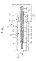
- Figs. 5A and 5B typically show the internal structure of the forearm 32 of the robot mechanism 10.
- cables partially branched from the control cables of the respective axis drive motors are connected to a geared third axis drive motor (or a J3 motor; not shown) and a fourth axis drive motor (or a J4 motor) 36 with a gear 34.
- the other umbilical members are passed through a cavity 38 inside the forearm 32 having the hollow structure.
- a clamp member 40 is provided, and control cables for the J3 motor and the J4 motor are branched from the position of the clamp member 40.
- the cable member 16 passed through the cavity 38 inside the forearm 32 is directed to a clamp member 42 provided near the outlet opening of the forearm 32. From the position of the clamp member 42, the control cable for a J5 motor 46 with a gear 44 and the control cable for a J6 motor 50 with a reduction gear 48 are branched.
- the other umbilical members of the cable member 16 i.e., the sensor cable for visual sensor 14 (or force sensor), the control cable for the hand 12, etc.
- the cable member 16 directed to the end-effector mount surface 54 is laid in such a manner as to entwine around a wrist member by using a space provided for giving a relative offset between the visual sensor 14 (or force sensor) and the hand 12. Finally, the sensor cable in the cable member 16 is connected to the visual sensor 14 (or force sensor) attached to the end-effector mount surface 44.
- the cable member 16 passed through the forearm 32 is repeatedly subjected to a bending and twisting action around the center of rotation, so that, unless any structural measure is made to the cable distribution and support equipment, the life of the cable and other umbilical members is shortened and the operation of the robot will be hindered.
- the sensor cable distribution and support equipment is designed in such a manner that a protective tube is provided to house the sensor cable for the visual sensor or force sensor together with the umbilical members including at least one of the control cable for the drive motor of the robot wrist axis, the control cable for the hand, and the pneumatic-mechanism driving compressed-air hose, and that the protective tube is laid through the cavity of the forearm.
- a protective tube is provided to house the sensor cable for the visual sensor or force sensor together with the umbilical members including at least one of the control cable for the drive motor of the robot wrist axis, the control cable for the hand, and the pneumatic-mechanism driving compressed-air hose, and that the protective tube is laid through the cavity of the forearm.
- cable distribution and support equipment 56 for a sensor is designed to arrange a protective tube 60 having a substantially circular cross-section in the cavity 38 of the forearm 32 supported on a forearm support 58 provided in the robot mechanism 10.
- the protective tube 60 is provided with a cantilever structure having a fixed end (a right end, in the drawing) 60a at a proximal side, adapted to be securely joined to the forearm support 58, and a free end (a left end, in the drawing) 60b adapted to be arranged in the cavity 38 of the forearm 32.
- a protective tube support 62 is provided to be formed integrally with the forearm support 58, or to be fabricated separately and fixed by a suitable fastening means to the forearm support 58.
- the protective tube 60 is supported in a cantilever fashion along the axis of rotation 32a of the forearm 32 by the protective tube support 62.
- the umbilical members 64a to 64e including the sensor cable for the visual sensor 14 (or force sensor), the control cable for the drive motor of the wrist axis, the control cable for the hand 12, the pneumatic-mechanism driving compressed-air hose, and others, in the above-described cable member 16, are passed through the protective tube 60.
- the five umbilical members 64a to 64e are shown in the drawing for facilitating illustration, the actual total number of umbilical members, passed through the protective tube 60, may be in the order from a few to one-hundred, or may be in some cases even more than that.
- the protective tube 60 is preferably fabricated from a material, such as a fluororesin (e.g., Teflon®), having a small sliding friction against the umbilical members, so that part of the umbilical members 64a to 64e passed through the tube 60 (e.g., the umbilical members 64a and 64e) will not come into contact with the inside surface of the tube 60 and thus will be damaged.
- the protective tube 60 has a rigidity such that the free end 60b will not contact the inside wall surface of the forearm 32 irrespective of the cantilever structure of the tube 60, while has a flexibility such that the umbilical members 64a to 64e housed inside the tube 60 will not be subjected to a excess stress.
- the inside diameter of the protective tube 60 is preferably a dimension maintaining a suitable clearance from the bundle of the umbilical members 64a to 64e housed in the tube 60.
- a cylindrical positioning member 66 having a large diameter part 66a and a small diameter part 66b is utilized to secure such a suitable clearance.
- the umbilical members 64a to 64e are bundled and restrained by the small diameter part 66b, and the large diameter part 66a is fit over the exposed outer circumference of the fixed end 60a of the protective tube 60, so as to maintain the clearance between the umbilical members 64a to 64e and the inner circumference of the protective tube 60.
- the sensor cable (denoted by, e.g., 64a) for the visual sensor 14 (or the force sensor), passed through the protective tube 60, may be comprised of a composite cable.
- the sensor cable is structured in such a manner that the image signal cable and control signal cable for the visual sensor 14 (or the detection-data transmission signal cable for the force sensor) and the power cable for the visual sensor 14 (or the force sensor) are covered together by a shield member, the outside of which is further covered by a sheath member.
- a shield member the outside of which is further covered by a sheath member.
- the sensor cable 64a for the visual sensor 14 is structured in such a manner that a twisted-pair signal cable 68 (comprised of signal wires 68a and 68b) for the image signal and control signal (or for the detection-data transmission) and a power cable 70 (comprised of power feed wires 70a and 70b) are cohered together by a shield 72, the outside of which is further covered by a sheath 74.
- a twisted-pair signal cable 68 it is also possible to use a coaxial signal cable.
- the sensor cable for the visual sensor 14 (or the force sensor) is structured in such a manner that a twisted-pair signal cable 68 (comprised of single wires 68a and 68b) for the image signal and control signal (or for the detection-data transmission) and a power cable 70 (comprised of power feed wires 70a and 70b) are respectively covered individually by shields 76 and 78.
- shields 76 and 78 At the portion housed in the protective tube 60, it is also possible to remove at least one of the shields 72, 76 and 78 and the sheath 74 in at least one of the twisted-pair signal cable 68 and the power cable 70.
- the protective tube 60 it is advantageous that at least one of the control cable for the drive motor of the wrist axis and the control cable of the hand 12 is passed through the protective tube 60 in the form of individual wires with no sheath members, from the viewpoint of making a cable bundle more compact and reducing the region occupied by it.
- the control cable is liable to be damaged by a rubbing caused between the control cable and the sheath 74. Therefore, for the insulating material of the individual wire forming the control cable, it is advantageous to use a material, such as Teflon®, containing an organic fluorine compound. According to this configuration, the lubrication between the umbilical members is improved and the damage to the umbilical members (in particular, the control cables) is effectively suppressed.
- the senor was explained as being either of a visual sensor or a force sensor, but these sensors may also be simultaneously attached to the region near the wrist of the robot.
- cable distribution and support equipment for a sensor similar to the above-described distribution and support equipment 56, to lay the sensor cables for the sensors inside the forearm 32.
- a sensor cable for a visual sensor or a force sensor can be readily laid inside a forearm of a robot, so that the interference between the sensor cable and the peripheral mechanism surrounding the forearm, in the operational space of the robot, can be avoided.
- the outside diameter of the cable bundle including the sensor cable would become larger, so that the inside diameters of the cavities of the forearm and the forearm support might have to be enlarged.
- the sensor cable is passed through a protective tube together with the other umbilical members such as the control cables, so that it is possible to arrange the protective tube spatially efficiently in the cavity inside the forearm of the robot, and thus that there is no longer a need to enlarge the cavities of the forearm and forearm support in order to pass the sensor cable therethrough.
- the robot system using the sensor cable distribution and support equipment according to the present invention it is possible to solve the problem of interference between the sensor cable and the peripheral mechanism surrounding the forearm in the operational space of the robot.
Applications Claiming Priority (2)
| Application Number | Priority Date | Filing Date | Title |
|---|---|---|---|
| JP2003387069 | 2003-11-17 | ||
| JP2003387069A JP2005144610A (ja) | 2003-11-17 | 2003-11-17 | センサケーブル配線処理構造 |
Publications (2)
| Publication Number | Publication Date |
|---|---|
| EP1531029A1 true EP1531029A1 (fr) | 2005-05-18 |
| EP1531029B1 EP1531029B1 (fr) | 2008-03-19 |
Family
ID=34431530
Family Applications (1)
| Application Number | Title | Priority Date | Filing Date |
|---|---|---|---|
| EP04026933A Expired - Fee Related EP1531029B1 (fr) | 2003-11-17 | 2004-11-12 | Dispositif de répartition et de support de cables de capteur dans un robot |
Country Status (4)
| Country | Link |
|---|---|
| US (1) | US20050103148A1 (fr) |
| EP (1) | EP1531029B1 (fr) |
| JP (1) | JP2005144610A (fr) |
| DE (1) | DE602004012515T2 (fr) |
Cited By (3)
| Publication number | Priority date | Publication date | Assignee | Title |
|---|---|---|---|---|
| EP1892064A1 (fr) * | 2006-08-24 | 2008-02-27 | Fanuc Ltd | Mécanisme d'entraînement pour bras de robot industriel |
| US10807251B2 (en) | 2018-04-11 | 2020-10-20 | Fanuc Corporation | Robot wrist structure |
| CN112423948A (zh) * | 2018-07-13 | 2021-02-26 | Fogale 纳米技术公司 | 设有电容检测和电容检测区域的电线的设备 |
Families Citing this family (23)
| Publication number | Priority date | Publication date | Assignee | Title |
|---|---|---|---|---|
| JP3830481B2 (ja) * | 2003-10-03 | 2006-10-04 | ファナック株式会社 | 産業用ロボット |
| KR100743611B1 (ko) * | 2006-03-28 | 2007-08-01 | 최광술 | 산업용 로봇의 케이블 조절장치 |
| KR100743612B1 (ko) * | 2006-03-28 | 2007-08-01 | 최광술 | 산업용 로봇의 케이블 조절장치 |
| US7781674B2 (en) * | 2006-11-28 | 2010-08-24 | Dorothy Kassab | Protective housing for wires |
| JP2008238320A (ja) * | 2007-03-27 | 2008-10-09 | Fanuc Ltd | 作業ツールを備えたロボット |
| JP4261598B2 (ja) | 2007-07-30 | 2009-04-30 | ファナック株式会社 | 産業用ロボットの線条体処理構造 |
| JP5353500B2 (ja) * | 2009-07-08 | 2013-11-27 | 株式会社安川電機 | ロボット |
| WO2011015189A1 (fr) * | 2009-08-04 | 2011-02-10 | Majatronic Gmbh | Robot parallèle |
| JP5450223B2 (ja) * | 2010-04-14 | 2014-03-26 | 株式会社ダイヘン | 産業用ロボット |
| JP5201186B2 (ja) * | 2010-09-16 | 2013-06-05 | 株式会社安川電機 | ロボット |
| EP2711145B1 (fr) * | 2011-05-13 | 2019-02-27 | Kawasaki Jukogyo Kabushiki Kaisha | Robot industriel à articulations multiples |
| JP2013212560A (ja) * | 2012-04-02 | 2013-10-17 | Seiko Epson Corp | ロボットシステムおよびロボット |
| JP5539454B2 (ja) | 2012-07-20 | 2014-07-02 | ファナック株式会社 | 中空部材を備えた産業用ロボットの線条体処理構造 |
| JP6671936B2 (ja) * | 2015-12-01 | 2020-03-25 | 株式会社Ihiプラント | 回転体機構及び観察装置 |
| JP6506195B2 (ja) * | 2016-03-09 | 2019-04-24 | ファナック株式会社 | 回転軸モジュールおよび多関節ロボット |
| JP6722099B2 (ja) * | 2016-12-09 | 2020-07-15 | 株式会社ダイヘン | 搬送システム |
| WO2018153444A1 (fr) | 2017-02-22 | 2018-08-30 | Abb Schweiz Ag | Système de robot industriel à capteur de surveillance |
| JP6462946B1 (ja) * | 2018-10-03 | 2019-01-30 | 株式会社トライフォース・マネジメント | 力覚センサ |
| JP6918368B2 (ja) * | 2018-12-18 | 2021-08-11 | 株式会社トライフォース・マネジメント | 力覚センサ |
| JP6488057B1 (ja) * | 2018-12-18 | 2019-03-20 | 株式会社トライフォース・マネジメント | 力覚センサ |
| JP6941402B1 (ja) * | 2019-02-13 | 2021-09-29 | 株式会社トライフォース・マネジメント | 力覚センサ |
| JP2022139292A (ja) * | 2021-03-11 | 2022-09-26 | 川崎重工業株式会社 | ロボットシステムおよびロボットシステムの組み立て方法 |
| FR3138337A1 (fr) * | 2022-07-29 | 2024-02-02 | Comau France | Machine-outil |
Citations (5)
| Publication number | Priority date | Publication date | Assignee | Title |
|---|---|---|---|---|
| GB950873A (en) * | 1961-03-28 | 1964-02-26 | Wandleside Cable Works Ltd | Improvements in or relating to electric heating cables |
| JPS60217094A (ja) * | 1984-04-13 | 1985-10-30 | 株式会社日立製作所 | 多自由度可動ミラ−ハンド付視覚装置 |
| EP0287062A1 (fr) * | 1987-04-13 | 1988-10-19 | Mitsubishi Denki Kabushiki Kaisha | Articulation pour robot industriel |
| US4819978A (en) * | 1986-06-27 | 1989-04-11 | California Institute Of Technology | Grasp force sensor for robotic hands |
| WO2003015998A1 (fr) * | 2001-08-02 | 2003-02-27 | Abb Ab | Robot industriel |
Family Cites Families (66)
| Publication number | Priority date | Publication date | Assignee | Title |
|---|---|---|---|---|
| US1487515A (en) * | 1921-05-02 | 1924-03-18 | Gen Electric | Thermal responsive switch |
| US1500572A (en) * | 1922-08-28 | 1924-07-08 | Brown William | Helicopter |
| US1820467A (en) * | 1928-04-13 | 1931-08-25 | Liska Joseph | Aeroplane propeller |
| US1824195A (en) * | 1929-04-13 | 1931-09-22 | Chillingworth Rudolph | Helicopter |
| US1893936A (en) * | 1931-06-12 | 1933-01-10 | Eriksson Andreas | Power means for aircraft |
| US2298576A (en) * | 1941-07-17 | 1942-10-13 | Internat Engineering Inc | Air handling apparatus |
| US2388973A (en) * | 1941-10-18 | 1945-11-13 | Harry A Hofgren | Airplane |
| US2874920A (en) * | 1955-10-20 | 1959-02-24 | George E Mallinckrodt | Aircraft |
| US3122342A (en) * | 1957-05-21 | 1964-02-25 | Weir Richard Lloyd | Rotary foil type aircraft |
| US2952442A (en) * | 1957-05-28 | 1960-09-13 | Studebaker Packard Corp | Rotating shroud |
| US2963272A (en) * | 1957-07-19 | 1960-12-06 | Gen Motors Corp | Rotor blade shrouding |
| US2988308A (en) * | 1958-02-05 | 1961-06-13 | Avro Aircraft Ltd | Vertical propulsion of aircraft |
| US3117630A (en) * | 1960-03-01 | 1964-01-14 | Barish Ass Inc | Rotors |
| US3112904A (en) * | 1961-08-18 | 1963-12-03 | Clinton A Reams | Take-off assisting apparatus for rotary wing aircraft |
| US3193215A (en) * | 1963-01-24 | 1965-07-06 | Mcmullen Ass John J | Aerodynamically designed amphibious vehicle |
| US3176413A (en) * | 1963-03-20 | 1965-04-06 | Dornier Werke Gmbh | Flyable helicopter pilot training apparatus |
| FR1388815A (fr) * | 1963-12-12 | 1965-02-12 | Véhicule tel qu'aéroplane | |
| US3273824A (en) * | 1965-02-04 | 1966-09-20 | Walter K Owens | Single passenger aircraft |
| AT270713B (de) * | 1966-06-22 | 1969-05-12 | Voest Ag | Blaseinrichtung für eine Konverteranlage und eine solche enthaltende Konverteranlage |
| US3437290A (en) * | 1967-04-24 | 1969-04-08 | Francis A Norman | Vertical lift aircraft |
| US3482803A (en) * | 1968-04-25 | 1969-12-09 | Bernard Lindenbaum | Heavy lift helicopter |
| US3635426A (en) * | 1968-09-12 | 1972-01-18 | Autogiro Co Of America | Rotary wing transport aircraft |
| US3695780A (en) * | 1970-10-19 | 1972-10-03 | Henry R Velkoff | Wheel-type airscrew having pre-tensioned blade supports |
| US3863869A (en) * | 1972-04-10 | 1975-02-04 | Flight Capsule Inc | VTOL capsule aircraft |
| US3752417A (en) * | 1972-06-23 | 1973-08-14 | P Lagace | Aircraft using lifting fans |
| US4037807A (en) * | 1972-09-01 | 1977-07-26 | Short Brothers And Harland Limited | Flight vehicle |
| US4076455A (en) * | 1976-06-28 | 1978-02-28 | United Technologies Corporation | Rotor blade system for a gas turbine engine |
| US4387867A (en) * | 1977-10-31 | 1983-06-14 | Technische Gerate-U Entwicklungsgesellschaft M.B.H. | Flying craft |
| US4232996A (en) * | 1978-10-06 | 1980-11-11 | The United States Of America As Represented By The Secretary Of The Air Force | Light weight fan assembly |
| US4312483A (en) * | 1978-10-13 | 1982-01-26 | Nicolae Bostan | Aircraft with circular wing |
| US4461436A (en) * | 1979-11-26 | 1984-07-24 | Gene Messina | Gyro stabilized flying saucer model |
| US4326836A (en) * | 1979-12-13 | 1982-04-27 | United Technologies Corporation | Shroud for a rotor blade |
| US4710102A (en) * | 1984-11-05 | 1987-12-01 | Ortolano Ralph J | Connected turbine shrouding |
| AUPM987994A0 (en) * | 1994-12-06 | 1995-01-05 | Stealth Propulsion International Limited | Improvements to propellers |
| US4778128A (en) * | 1985-04-17 | 1988-10-18 | Wright Herbert H | Flying disc aircraft |
| FR2584044B1 (fr) * | 1985-09-27 | 1987-08-21 | Pauchard Daniel | Aeronef a ailes tournantes de structure simplifiee et legere |
| US4767270A (en) * | 1986-04-16 | 1988-08-30 | The Boeing Company | Hoop fan jet engine |
| US4773618A (en) * | 1987-01-21 | 1988-09-27 | Ow Gordon J W | High speed vertical take-off and landing aircraft |
| DE3832026A1 (de) * | 1988-09-21 | 1990-03-22 | Bosch Gmbh Robert | Luefterrad |
| US5086993A (en) * | 1989-02-09 | 1992-02-11 | Aca Industries | Airplane with variable-incidence wing |
| US5096382A (en) * | 1989-05-17 | 1992-03-17 | Gratzer Louis B | Ring-shrouded propeller |
| US5001304A (en) * | 1989-07-25 | 1991-03-19 | At&T Bell Laboratories | Building riser cable |
| US5152478A (en) * | 1990-05-18 | 1992-10-06 | United Technologies Corporation | Unmanned flight vehicle including counter rotating rotors positioned within a toroidal shroud and operable to provide all required vehicle flight controls |
| US5120197A (en) * | 1990-07-16 | 1992-06-09 | General Electric Company | Tip-shrouded blades and method of manufacture |
| GB2251034B (en) * | 1990-12-20 | 1995-05-17 | Rolls Royce Plc | Shrouded aerofoils |
| US5259671A (en) * | 1991-06-07 | 1993-11-09 | Farrel Corporation | Greased journal bearing assemblies with thermal isolation and cooling in continuous mixers of plastic materials |
| US5297759A (en) * | 1992-04-06 | 1994-03-29 | Neil Tilbor | Rotary aircraft passively stable in hover |
| US5269656A (en) * | 1992-09-30 | 1993-12-14 | The United States Of America As Represented By The Secretary Of The Navy | High damping limp propeller |
| US5421638A (en) * | 1993-02-26 | 1995-06-06 | Mts Northwest Sound, Inc. | Seat attachment |
| US5419513A (en) * | 1993-05-11 | 1995-05-30 | United Technologies Corporation | Ancillary aerodynamic structures for an unmanned aerial vehicle having ducted, coaxial counter-rotating rotors |
| JP3107266B2 (ja) * | 1993-09-17 | 2000-11-06 | 株式会社日立製作所 | 流体機械および流体機械の翼装置 |
| US5507453A (en) * | 1993-12-21 | 1996-04-16 | Shapery; Sandor W. | Gyro stabilized vectored thrust vertical takeoff or landing aircraft |
| US5437541A (en) * | 1993-12-30 | 1995-08-01 | Vainrub; John | Blade for axial fan |
| US5727754A (en) * | 1995-08-31 | 1998-03-17 | Cartercopters, L.L.C. | Gyroplane |
| US5890441A (en) * | 1995-09-07 | 1999-04-06 | Swinson Johnny | Horizontal and vertical take off and landing unmanned aerial vehicle |
| US5961289A (en) * | 1995-11-22 | 1999-10-05 | Deutsche Forshungsanstalt Fur Luft-Und Raumfahrt E.V. | Cooling axial flow fan with reduced noise levels caused by swept laminar and/or asymmetrically staggered blades |
| US5860788A (en) * | 1996-06-14 | 1999-01-19 | Shell Electric Mfg. (Holdings) Co. Ltd. | Low drag fan assembly |
| US5860620A (en) * | 1996-07-10 | 1999-01-19 | Northrup Grumman Corporation | Ram wing vehicle |
| CA2195581A1 (fr) * | 1997-01-21 | 1998-07-21 | Stanley Ronald Meek | Aeronef trimodal gyrostabilise |
| US5829956A (en) * | 1997-04-22 | 1998-11-03 | Chen; Yung | Fan blade assembly |
| US6065937A (en) * | 1998-02-03 | 2000-05-23 | Siemens Canada Limited | High efficiency, axial flow fan for use in an automotive cooling system |
| US6015258A (en) * | 1998-04-17 | 2000-01-18 | Taylor; Ronald J. | Wind turbine |
| US6243508B1 (en) * | 1999-06-01 | 2001-06-05 | Picolight Incorporated | Electro-opto-mechanical assembly for coupling a light source or receiver to an optical waveguide |
| US6435835B1 (en) * | 1999-12-20 | 2002-08-20 | United Technologies Corporation | Article having corrosion resistant coating |
| US6513752B2 (en) * | 2000-05-22 | 2003-02-04 | Cartercopters, L.L.C. | Hovering gyro aircraft |
| US6572081B2 (en) * | 2000-12-27 | 2003-06-03 | Nkf Kabel B.V. | Installation of guide tubes in a protective duct |
-
2003
- 2003-11-17 JP JP2003387069A patent/JP2005144610A/ja active Pending
-
2004
- 2004-11-12 EP EP04026933A patent/EP1531029B1/fr not_active Expired - Fee Related
- 2004-11-12 DE DE602004012515T patent/DE602004012515T2/de not_active Expired - Fee Related
- 2004-11-17 US US10/989,431 patent/US20050103148A1/en not_active Abandoned
Patent Citations (5)
| Publication number | Priority date | Publication date | Assignee | Title |
|---|---|---|---|---|
| GB950873A (en) * | 1961-03-28 | 1964-02-26 | Wandleside Cable Works Ltd | Improvements in or relating to electric heating cables |
| JPS60217094A (ja) * | 1984-04-13 | 1985-10-30 | 株式会社日立製作所 | 多自由度可動ミラ−ハンド付視覚装置 |
| US4819978A (en) * | 1986-06-27 | 1989-04-11 | California Institute Of Technology | Grasp force sensor for robotic hands |
| EP0287062A1 (fr) * | 1987-04-13 | 1988-10-19 | Mitsubishi Denki Kabushiki Kaisha | Articulation pour robot industriel |
| WO2003015998A1 (fr) * | 2001-08-02 | 2003-02-27 | Abb Ab | Robot industriel |
Cited By (3)
| Publication number | Priority date | Publication date | Assignee | Title |
|---|---|---|---|---|
| EP1892064A1 (fr) * | 2006-08-24 | 2008-02-27 | Fanuc Ltd | Mécanisme d'entraînement pour bras de robot industriel |
| US10807251B2 (en) | 2018-04-11 | 2020-10-20 | Fanuc Corporation | Robot wrist structure |
| CN112423948A (zh) * | 2018-07-13 | 2021-02-26 | Fogale 纳米技术公司 | 设有电容检测和电容检测区域的电线的设备 |
Also Published As
| Publication number | Publication date |
|---|---|
| DE602004012515T2 (de) | 2009-04-16 |
| DE602004012515D1 (de) | 2008-04-30 |
| US20050103148A1 (en) | 2005-05-19 |
| EP1531029B1 (fr) | 2008-03-19 |
| JP2005144610A (ja) | 2005-06-09 |
Similar Documents
| Publication | Publication Date | Title |
|---|---|---|
| EP1531029B1 (fr) | Dispositif de répartition et de support de cables de capteur dans un robot | |
| EP2006056B1 (fr) | Robot industriel avec un câble ombilical et un câble plat disposés le long d'un élément d'articulation de poignet | |
| US7703349B2 (en) | Cable laying structure for robot | |
| US9770831B2 (en) | Industrial robot | |
| EP1625920B1 (fr) | Structure de guidage pour un câble ombilical d'un robot industriel | |
| US7196285B2 (en) | Structure for managing umbilical member of welding torch in arc welding robot | |
| US5777267A (en) | Harness assembly to provide signals to end effector | |
| CN107538477B (zh) | 机器人、控制装置及机器人系统 | |
| US4969795A (en) | Industrial robot equipped with a cable extending means | |
| EP1257390B1 (fr) | Robot industriel | |
| JPH10175188A (ja) | ロボットの構造 | |
| JP4349320B2 (ja) | マニピュレータ型ロボット | |
| JP2007015053A (ja) | 産業用ロボット | |
| US6153828A (en) | Supporting device for wiring and piping of industrial robot | |
| CA2196517C (fr) | Robot industriel | |
| JP3929383B2 (ja) | 産業用ロボットのカメラ及び力センサケーブル処理構造 | |
| JP7388887B2 (ja) | ロボットの線条体ユニットおよび線条体配線方法 | |
| JPH0214267Y2 (fr) | ||
| JP2635466B2 (ja) | 関節運動型ロボットアーム用電気配線 | |
| WO2021192139A1 (fr) | Faisceau de câbles, procédé de production de faisceau de câbles, robot industriel ayant un faisceau de câbles | |
| WO2023248349A1 (fr) | Dispositif d'entraînement et robot équipé d'un dispositif d'entraînement | |
| JPS5997888A (ja) | 工業用ロボツト | |
| JPH04269192A (ja) | 産業用ロボツト | |
| WO2022138370A1 (fr) | Actionneur à corps de filament intégré, unité et robot | |
| JPH04336993A (ja) | 産業用ロボットのケーブル処理装置 |
Legal Events
| Date | Code | Title | Description |
|---|---|---|---|
| PUAI | Public reference made under article 153(3) epc to a published international application that has entered the european phase |
Free format text: ORIGINAL CODE: 0009012 |
|
| 17P | Request for examination filed |
Effective date: 20050209 |
|
| AK | Designated contracting states |
Kind code of ref document: A1 Designated state(s): AT BE BG CH CY CZ DE DK EE ES FI FR GB GR HU IE IS IT LI LU MC NL PL PT RO SE SI SK TR |
|
| AX | Request for extension of the european patent |
Extension state: AL HR LT LV MK YU |
|
| AKX | Designation fees paid |
Designated state(s): DE |
|
| 17Q | First examination report despatched |
Effective date: 20061128 |
|
| GRAP | Despatch of communication of intention to grant a patent |
Free format text: ORIGINAL CODE: EPIDOSNIGR1 |
|
| GRAS | Grant fee paid |
Free format text: ORIGINAL CODE: EPIDOSNIGR3 |
|
| GRAA | (expected) grant |
Free format text: ORIGINAL CODE: 0009210 |
|
| AK | Designated contracting states |
Kind code of ref document: B1 Designated state(s): DE |
|
| REF | Corresponds to: |
Ref document number: 602004012515 Country of ref document: DE Date of ref document: 20080430 Kind code of ref document: P |
|
| PLBE | No opposition filed within time limit |
Free format text: ORIGINAL CODE: 0009261 |
|
| STAA | Information on the status of an ep patent application or granted ep patent |
Free format text: STATUS: NO OPPOSITION FILED WITHIN TIME LIMIT |
|
| PGFP | Annual fee paid to national office [announced via postgrant information from national office to epo] |
Ref country code: DE Payment date: 20081126 Year of fee payment: 5 |
|
| 26N | No opposition filed |
Effective date: 20081222 |
|
| PG25 | Lapsed in a contracting state [announced via postgrant information from national office to epo] |
Ref country code: DE Free format text: LAPSE BECAUSE OF NON-PAYMENT OF DUE FEES Effective date: 20100601 |