EP1530400B1 - Audioregler für ein Kraftfahrzeug mit Vibrationssensor - Google Patents
Audioregler für ein Kraftfahrzeug mit Vibrationssensor Download PDFInfo
- Publication number
- EP1530400B1 EP1530400B1 EP04022555A EP04022555A EP1530400B1 EP 1530400 B1 EP1530400 B1 EP 1530400B1 EP 04022555 A EP04022555 A EP 04022555A EP 04022555 A EP04022555 A EP 04022555A EP 1530400 B1 EP1530400 B1 EP 1530400B1
- Authority
- EP
- European Patent Office
- Prior art keywords
- signal
- vibration
- audio signal
- level
- audio
- Prior art date
- Legal status (The legal status is an assumption and is not a legal conclusion. Google has not performed a legal analysis and makes no representation as to the accuracy of the status listed.)
- Expired - Lifetime
Links
Images





Classifications
-
- G—PHYSICS
- G11—INFORMATION STORAGE
- G11B—INFORMATION STORAGE BASED ON RELATIVE MOVEMENT BETWEEN RECORD CARRIER AND TRANSDUCER
- G11B20/00—Signal processing not specific to the method of recording or reproducing; Circuits therefor
- G11B20/10—Digital recording or reproducing
-
- H—ELECTRICITY
- H03—ELECTRONIC CIRCUITRY
- H03G—CONTROL OF AMPLIFICATION
- H03G3/00—Gain control in amplifiers or frequency changers
- H03G3/20—Automatic control
- H03G3/30—Automatic control in amplifiers having semiconductor devices
- H03G3/32—Automatic control in amplifiers having semiconductor devices the control being dependent upon ambient noise level or sound level
-
- H—ELECTRICITY
- H04—ELECTRIC COMMUNICATION TECHNIQUE
- H04R—LOUDSPEAKERS, MICROPHONES, GRAMOPHONE PICK-UPS OR LIKE ACOUSTIC ELECTROMECHANICAL TRANSDUCERS; ELECTRIC HEARING AIDS; PUBLIC ADDRESS SYSTEMS
- H04R3/00—Circuits for transducers
- H04R3/04—Circuits for transducers for correcting frequency response
Definitions
- This invention relates to a sound system for an automobile, and more particularly, to a sound system capable of dynamically adjusting gain and tone characteristics for a reproduced audio signal in accordance with a vibration level in the automobile.
- Ambient noise in automobiles caused by, for example, the engine or the interaction of the tires and the road surface, may not be band-limited but usually has strong components below approximately 200 Hz. This low frequency ambient noise causes problems for automotive audio reproduction systems.
- the volume of the signal as perceived by a listener commonly referred to as the "apparent volume,” is a function of the noise, and hence, the apparent volume decreases as the noise increases. Listeners may wish to maintain the apparent volume at a constant level, but this is difficult as the ambient noise changes dynamically in an automobile, for example, because of changing road conditions and/or changing automobile speeds. This problem often is referred to as the "apparent volume problem.”
- noise-only-method One method of compensating for the apparent volume problem, referred to as the "noise-only-method," involves increasing the gain of the signal as a function of the ambient noise. This method prevents soft passages from being overwhelmed by the noise.
- the method may be disadvantageous because it varies the gain irrespective of the volume level set by the user, so the method increases the gain in response to increasing noise even for very high volume levels. These increases may result in producing signals that are painfully loud for a listener, harmful to the audio reproduction equipment, or both.
- systems designed to compensate for either the apparent volume problem or the uneven masking problem include some way of estimating the level of the ambient noise.
- Some automotive audio reproduction systems use a microphone located inside the passenger compartment of the automobile to measure ambient noise.
- the use of a microphone in the passenger compartment may have several disadvantages. Since the microphone is generally sensitive to all sounds in the automobile, including the signals generated by the audio reproduction system, it may be necessary to filter the signal generated by the microphone to yield a signal representative of the noise.
- One method for filtering the microphone output signal involves use a low pass filter to remove higher frequencies where the reproduced audio signal may be concentrated. This method, however, may generate a signal that represents only the sub-audio low-frequency noise, rather than the actual masking noise that may contain higher frequencies.
- Another method of filtering the microphone signal is to subtract the reproduced audio signal from the microphone signal to obtain a signal representative of the noise.
- This method may be disadvantageous because it involves the transfer function from the speakers of the audio reproduction system to the microphone. The transfer function may be difficult to determine, and, moreover, may vary dynamically, for example, with changes in the number of passengers in the automobile.
- using a microphone in the passenger compartment of the automobile may cause increases in the signal in response to speech of passengers, so that the audio reproduction system may attempt to "drown out" conversations.
- the US Patent No. 5,872,852 discloses a noise estimating system that comprises a memory means for storing noise values that are representative of ambient noise and are used in the generation of an enhanced audio signal.
- the disclosed system may further comprise a vibration sensor that produces a vibration signal that can be used for the generation of an enhanced audio signal.
- JP 58 179009 A a control means for automatically controlling the sound volume of an on-vehicle device is described. The control is achieved by the usage of the filtered output signal of a vibration sensor.
- DE 22 25 575 A also relates to the automatic volume control for on-vehicle devices.
- the gain of the on-vehicle devices is controlled by means of an output signal of a vibration sensor that is filtered at certain frequencies only.
- An automotive audio controller comprising the features according to claim 1 is provided for receiving an audio signal from an audio source and providing a filtered audio signal that compensates for ambient noise in the automobile.
- the dynamic filter may increase the gain level of the audio signal as the vibration signal increases to generate the filtered audio signal.
- the audio controller also may receive a speed signal and change the gain level and/or tone of the audio signal based on the speed signal to generate the filtered audio signal.
- the dynamic filter may increase the gain level of the audio signal as the speed signal increases to generate the filtered audio signal.
- the audio controller also may receive a volume control signal.
- the volume control signal may affect how the dynamic filter changes the audio signal as a function of the vibration and/or speed signals. For example, when the volume control signal is low, the dynamic filter may increase the gain level of the audio signal by a first factor as the speed signal and/or the vibration signal increases in order to generate the filtered audio signal. When the volume control signal is high, however, the dynamic filter may increase the gain level of the audio signal by a second factor, or not at all, as the speed signal and/or the vibration signal increases in order to generate the filtered audio signal.
- FIG. 1 is a block diagram for an example automotive audio controller.
- FIG. 2 is an example flow chart for the example automotive audio controller of FIG. 1 .
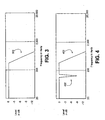
- FIG. 3 is a frequency response graph for an example vibration filter of an automotive audio controller including a bass-shelf filter.
- FIG. 4 is a frequency response graph for a second example vibration filter of an automotive audio controller including a notch filter with a bass-shelf filter.
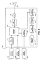
- FIG. 5 is a block diagram for a second example automotive audio controller including a speed sensor and a speed estimator.
- FIG. 6 is an example flow chart for the second example automotive audio controller of FIG. 5 .
- FIG. 7 is a block diagram for a third example automotive audio controller including volume control.
- FIG. 8 is an example flow chart for the third example automotive audio controller of FIG. 7 .
- FIG. 1 A first example automotive audio controller 102 for use in an automobile is shown in FIG. 1 .
- the term “automotive audio controllers” as used herein refers to items known in the vernacular as “car stereos” or “car stereo components.” Automotive audio controllers are frequently installed in most types of motorized vehicles.
- the term “automobile” as used herein refers to motorized vehicles, such as motorcycles, boats, fixed or rotary wing aircraft, or any other vehicles that have an engine and transport passengers.
- the term “passenger compartment” is used herein to refer to a space in or on a vehicle that is occupied by passengers, such as the cabin of a car or an aircraft, or the space generally between the handlebars and the taillight of a motorcycle.
- the automotive audio controller 102 may be coupled to an analog audio source 104, a digital audio source 106, and at least one speaker 124.
- the automotive audio controller 102 may be configured to accept an analog audio signal from the analog audio source 104 and a digital audio signal from the digital audio source 106.
- the automotive audio controller 102 may generate a driving electrical signal to drive the speaker 124.
- the automotive audio controller 102 may include a vibration sensor 108 that generates a vibration level signal indicative of vibration.
- the driving electrical signal may be based on the analog and/or digital audio signals and the vibration level signal.
- the automotive audio controller 102 may "compensate" the driving electrical signal for ambient noise in the automobile passenger compartment by, for example, raising the level and/or changing the tone of the driving electrical signal in response to increases in the ambient noise level.
- the analog and/or digital audio signals may be multi-channel signals, such as stereo or surround sound signals.
- the automotive audio controller 102 may include an amplifier 122 that is coupled to the speaker 124.
- the amplifier 122 may comprise a stereo or multi-channel amplifier, such as a five or seven channel surround sound amplifier with or without a subwoofer amplifier.
- the speaker 124 may include a plurality of speakers coupled to the channels of the amplifier 122 to reproduce the stereo or multi-channel audio.
- the vibration sensor 108 may include any type of vibration sensor capable of sensing vibrations and generating an analog or digital signal indicating the frequency and amplitude of sensed vibrations.
- the vibration sensor 108 may include a mass loaded cantilever vibration sensor.
- One such vibration sensor is the Minisense 100-HT vibration sensor produced by Measurement Specialties, Inc. of Wayne, Pennsylvania.
- the vibration sensor 108 may be mounted to the automobile such that vibrations caused by interaction between the tires and the road or by wind moving across the automobile, as well as vibrations caused by the engine or other moving parts, excite (vibrate) the vibration sensor 108.
- the vibration sensor 108 may be mounted in the dash, under a seat, between the roof and the headliner, in one of the doors, in the trunk, to the frame, or the like.
- the analog audio source 104 may include a terrestrial or satellite radio receiver, a cassette tape player, a compact disc player ("CD player”), a minidisk player (“MD player”), an eight-track tape player, a digital audio tape player (“DAT player”), a digital versatile disc player (“DVD player”), an MPEG layer 3 audio player (“MP3 player”) or other devices that produce an analog audio signal.
- CD player compact disc player
- MD player minidisk player
- DAT player digital audio tape player
- DVD player digital versatile disc player
- MP3 player MPEG layer 3 audio player
- the digital audio source 106 may include a CD player, an MD player, DAT player, a DVD player, an MP3 player, a digital radio receiver, or a similar device that is capable of generating a digital audio output.
- the digital audio source 106 may provide, via an optical Toshiba® Link (“TOSLINK®”) and/or an electrical Sony® / Phillips® digital interface (“S/PDIF”), a pulse-code modulated (“PCM”), a digital theater systems (“DTS®”), or a Dolby® Digital signal.
- TOSLINK® optical Toshiba® Link
- S/PDIF electrical Sony® / Phillips® digital interface
- PCM pulse-code modulated
- DTS® digital theater systems
- Dolby® Digital signal a Dolby® Digital signal.
- the digital audio source 106 also may provide a digital audio signal through a wide area or local area network, such as such as a MOST® network, a COBRANet® network, an Ethernet® network, a universal serial bus (“USB®”) network, and/or other types of wired or wireless networks.
- a wide area or local area network such as such as a MOST® network, a COBRANet® network, an Ethernet® network, a universal serial bus (“USB®”) network, and/or other types of wired or wireless networks.
- the automotive audio controller 102 may include first and second analog-to-digital converters ("A/D converters”) 110 and 112, dynamic filters 118, vibration filters 114, a power estimator 116, a digital-to-analog converter ("D/A converter") 120, and an amplifier 122.
- the A/D converters 110 and 112 may each be a device that translates a continuously varying (analog) signal, such as a voltage or a current, to a succession of discrete digital values.
- Each A/D converter 110 and 112 may sample an analog signal periodically and produce a digital value representing the amplitude of the analog signal for each sample.
- the first A/D converter 110 may be coupled to the analog audio source 104 and may sample the analog audio signal at around 44.1 kHz or above and produce an 8-bit to 24-bit number representing the amplitude of the analog audio signal for each sample.
- the second A/D converter 112 may be coupled to the vibration sensor 108 and may sample the analog vibration signal at, for example, 1 kHz or above and produce a 4-bit to 24-bit number representing the amplitude of the vibration signal for each sample.
- the D/A converter 120 may be a device that translates digital data to an analog signal, such as a line-level signal.
- the D/A converter 120 may be coupled to and receive a succession of discrete digital values from the dynamic filters 118 as an input.
- the D/A converter 120 also may be coupled to the amplifier 122, and may create an analog signal as an output thereto, the amplitude of which corresponds to each digital value in time.
- the dynamic filters 118 may be a digital signal processor ("DSP") capable of receiving a plurality of digital audio signals and one or more control signals, and altering and/or switching between the digital audio signals either as a function of the control signals, or in a predetermined fashion.
- DSP digital signal processor
- the term "filters” is used here and elsewhere rather than terms such as “filter(s)” or “filtering means” to describe one or more filters, and should not be read to limit the claimed invention in any way.
- the dynamic filters 118 may be coupled to and receive digital audio signals from the first A/D converter 110 and the digital audio source 106.
- the dynamic filters 118 also may be coupled to and receive a control signal from the power estimator 116.
- the amplifier 122 may be an audio amplifier capable of receiving an analog audio signal, such as a line-level signal, and amplifying it to a level sufficient to a loudspeaker.
- the amplifier 122 may be an automotive stereo or surround sound amplifier.
- the amplifier 122 may be coupled to and receive an analog audio signal from the D/A converter 120.
- the amplifier 122 may be coupled to and provide a driving electrical signal to the speaker 124.
- the vibration filters 114 may be a DSP capable of receiving a digital vibration signals and altering the digital vibration signals in a predetermined fashion.
- the vibration filters 114 may be coupled to the second A/D converter 112.
- the power estimator 116 may be a DSP or a controller capable of generating a normalized power value indicative of the relative level of vibration sensed by the vibration sensor. For example, the power estimator may be tuned to a particular model of automobile, and may generate a normalized vibration power value between 0 and 100.
- the power estimator 116 may be coupled between the vibration filters 114 and the dynamic filters 118.
- the analog source 104 may transmit an analog audio signal to the first A/D converter 110.
- the first A/D converter 110 may convert the analog audio signal to a first digital audio signal, and transmit the first digital audio signal to the dynamic filters 118.
- the digital source 106 may transmit a second digital audio signal directly to the dynamic filters 118.
- the analog and digital audio signals may each be a monophonic, stereophonic, or multi-channel audio signal.
- the dynamic filters 118 may receive the digital audio signals from the digital source 106 and/or the first A/D converter 110. One of these digital audio signal may be selected, for example by a selection control signal (not shown), altered (filtered), and transmitted by the dynamic filters 118 to the D/A converter 120.
- the D/A converter 120 may convert the filtered digital audio signal to a filtered analog audio signal.
- the filtered analog audio signal may be sent by the D/A converter 120 to the amplifier 122.
- the amplifier 122 may amplify the filtered analog audio signal to drive the speaker 124.
- FIG. 2 is an example flow chart for the first automotive audio controller 102.
- the second A/D converter 112 may convert an analog vibration signal from the vibration sensor 108 into a digital vibration signal.
- the vibration filters 114 may receive a digital vibration signal from the second A/D converter 112.
- the vibration filters 114 may implement a combination of bass-shelf (low pass), treble-shelf (high pass), Peak and/or Notch filters. Particular filters implemented in the vibration filters 114 may be customized for different automobile models.
- the vibration filters 114 may include a bass-shelf filter that has a cutoff frequency of 500 Hz.
- a frequency response plot for an example bass-shelf filter with a cutoff frequency 302 of 500 Hz is shown in FIG. 3 .
- the vibration sensor 108 may be near a vibration source inside the automobile, such as an air conditioner fan vibrating at a frequency of 100 Hz.
- the vibration filters 114 may include a notch filter centered at 100 Hz, in addition to a bass-shelf filter that has a cutoff frequency of 500 Hz.
- a frequency response plot for an example notch filter with a center frequency 402 of 500 Hz combined with a bass-shelf filter that has a cutoff frequency 404 of 500 Hz is shown in FIG. 4 .
- the vibration filters 114 also may include high-pass and low-pass filters of various orders.
- the vibration filters 114 may include a low-pass filter with a cutoff frequency of about 20 kHz to filter out vibrations above the audible range, and a high-pass filter with a cutoff frequency of about 2 Hz to filter out direct current (DC) signals.
- DC direct current
- the vibration filters 114 may transmit a filtered vibration signal to the power estimator 116.
- the power estimator 116 also may be customized for different automobile models.
- the power estimator 116 may generate a normalized vibration level value indicative of a relative level of vibration sensed by the vibration sensor, such that the normalized vibration level value is consistent from one automobile model to another.
- a first model of automobile may have a maximum filtered vibration signal level of 200
- a second model of automobile may have a maximum filtered vibration signal level of 50.
- the power estimator 116 may normalize the filtered vibration signal levels in the first automobile model by dividing by two, and normalize the filtered vibration signal levels in the second automobile model by multiplying by two. Such normalizing may allow the dynamic filters 118 to be designed for operation in a wider range of automobile models.
- the power estimator 116 may square and/or integrate and/or determine a root of the received filtered vibration signal to determine the normalized vibration level value. Where each of these three operations is carried out, the normalized vibration level value may be a function of the root-mean-square (RMS) power level of the filtered vibration signal.
- RMS root-mean-square
- the power estimator 116 may integrate (average) the received filtered vibration signal over time in order to smooth level transitions in the filtered signal.
- the filtered vibration signal may be averaged over a period of ten seconds. The averaging may lessen sudden, unnatural, adjustments to the filtered signal.
- the automobile hits a bump there may be an extreme, but short duration, increase in vibration level.
- a corresponding increase (without averaging) to the filtered signal could startle passengers, or have other negative consequences.
- the power estimator 116 may bound the normalized vibration level value over time. For example, the power estimator 116 may limit (bound) the normalized vibration level value to plus or minus around 15% of an averaged normalized vibration level value over a period of time, such as five seconds. Such bounding may help to reduce sudden, unnatural, adjustments to the filtered signal.
- the dynamic filters 118 may receive the normalized vibration level value from the power estimator 116 in addition to the audio signals.
- the dynamic filters 118 may include high-pass, band-pass, and/or low-pass filters of various orders to adjust the tone of the filtered digital audio signal, and also may be capable of adjusting the overall level of the filtered digital audio signal.
- the dynamic filters 118 may increase the level of the filtered digital audio signal as a function of the normalized vibration level value. For example, the level of the filtered digital audio signal may be increased proportionally to the normalized vibration level value.
- the dynamic filters 118 may increase the level of certain frequency ranges of the filtered digital audio signal as a function of the normalized vibration level value. For example, the "bass" (low frequency range) level of the filtered digital audio signal may be increased more than other frequency ranges.
- the automotive audio controller 102 may be configured differently for different models. For example, ambient noise and vibration characteristics may be measured for an automobile model on test tracks to determine ambient noise characteristics as a function of vibration. These measured characteristics may be used to configure the vibration filters 114, the power estimator 116, and the dynamic filters 118 for the automobile model.
- a second example automotive audio controller 502 is shown in FIG. 5 including a speed sensor 504 and a speed estimator 506.
- the automotive audio controller 502 may be configured to accept analog and/or digital audio signals and include the vibration sensor 108 to generate a vibration level signal, in the same manner as the first automotive audio controller 102 described above.
- the second automotive audio controller 502 also may be coupled to and receive a speed signal from a speed sensor 504.
- the speed sensor 504 may be, for example, a speedometer having a digital output.
- the speed sensor may transmit the speed signal directly to the automotive audio controller 502, or may transmit the speed signal through an automotive interface bus.
- the automotive audio controller 502 may generate a driving electrical signal to drive the speaker 124 in the same manner as the automotive audio controller 102.
- the automotive audio controller 502 may include the A/D converters 110 and 112, the vibration filters 114, the power estimator 116, the D/A converter 120, the amplifier 122, a speed estimator 506, and dynamic filters 508. Except for the speed sensor 506, the components of the second example automotive audio controller 502 may be configured in the same manner as the components in the first example automotive controller 102.
- FIG. 6 is an example flow chart for the second automotive audio controller 502. At 602-610, the second automotive audio controller 502 may operate in the same fashion as the first automotive audio controller 102.
- the speed estimator 506 may be coupled between the speed sensor 504 and the dynamic filters 508. At 612, the speed estimator 506 may receive the speed signal from the speed sensor 504 and convert the speed signal into a speed value, such as a numerical indicator of speed in kilometers per hour or miles per hour. The speed estimator 506 may transmit the speed value to the dynamic filters 508.
- a speed value such as a numerical indicator of speed in kilometers per hour or miles per hour.
- the speed estimator 506 may transmit the speed value to the dynamic filters 508.
- the dynamic filters 508 may be a DSP capable of receiving a plurality of digital audio signals and one or more control signals, and altering and/or switching between the digital audio signals either as a function of the control signals, or in a predetermined fashion.
- the dynamic filters 508 may receive the normalized vibration level value from the power estimator 116 and the speed value from the speed estimator 506 in addition to the audio signals.
- the dynamic filters 508 may include high-pass, band-pass, and/or low-pass filters of various orders to adjust the tone and/or the level of the filtered digital audio signal.
- the dynamic filters 508 may increase the level of the filtered digital audio signal as a function of the normalized vibration level value, as a function of the speed value, or as a function of both.
- the level of the filtered digital audio signal may be increased proportionally to the normalized vibration level value, proportionally to the speed value, or proportionally to both the normalized vibration level value and the speed value.
- the dynamic filters 508 may increase the level of certain frequency ranges of the filtered digital audio signal as a function of the normalized vibration level value, as a function of the speed value, or as a function of both.
- the "bass" (low frequency range) level of the filtered digital audio signal may be increased more than other frequency ranges when the normalized vibration level value increases
- the "treble" (high frequency range) level of the filtered digital audio signal may be increased more than other frequency ranges when the speed value increases.
- Such a configuration may be desirable where a high speed value indicates an increase in wind noise, which may be concentrated in higher frequencies for a certain automobile model.
- a third example automotive audio controller 702 is shown in FIG. 7 .
- the automotive audio controller 702 may be configured to accept analog and/or digital audio signals and a speed signal, and include the vibration sensor 108 to generate a vibration level signal, in the same manner as the first and second automotive audio controllers 102 and 502.
- the third automotive audio controller 702 may include the A/D converters 110 and 112, the vibration filters 114, the power estimator 116, the D/A converter 120, the amplifier 122, the speed estimator 506, and dynamic filters 706.
- the dynamic filters 706 may be a DSP capable of receiving a plurality of digital audio signals and one or more control signals, and altering and/or switching between the digital audio signals either as a function of the control signals, or in a predetermined fashion.
- the components of the third example automotive audio controller 702 may be configured in the same manner as the components in the second example automotive controller 502.
- the third automotive audio controller 702 may, however, also be coupled to a volume control 704.
- the third automotive audio controller 702 may receive a volume control signal from the volume control 704.
- the volume control 704 may be, for example, a manually actuated potentiometer with an A/D converter to generate a volume control signal, a jog/shuttle control generating pulses, or the like.
- FIG. 8 is an example flow chart for the second automotive audio controller 702.
- the third automotive audio controller 702 may operate in the same fashion as the second automotive audio controller 502.
- the volume control 704 may transmit the volume control signal directly to the third automotive audio controller 702, or may transmit the volume control signal through an automotive interface bus.
- the third automotive audio controller 702 may generate a driving electrical signal to drive the speaker 124 in the same manner as the automotive audio controller 502.
- the dynamic filters 706 may receive the normalized vibration level value from the power estimator 116, the speed signal from the speed estimator 506, and the volume control signal from the volume control 704 in addition to the audio signals.
- the dynamic filters 706 may include high-pass, band-pass, and/or low-pass filters of various orders to adjust the tone of the filtered digital audio signal, and also may adjust the level of the filtered digital audio signal.
- the dynamic filters 706 may increase the level of the filtered digital audio signal as a function of the volume control signal, and also as a function of the normalized vibration level value and/or the speed value.
- the level of the filtered digital audio signal may be increased proportionally to a level of the volume control signal.
- the level of the volume control signal when the level of the volume control signal is low (i.e., below a first threshold), at 818 the level of the filtered digital audio signal may be increased at a first rate based on the normalized vibration level value, at a first rate based on the speed value, or at a first rate based on both the normalized vibration level value and the speed value.
- the level of the filtered digital audio signal may be increased at a second rate based on the normalized vibration level value and/or the speed value, because the "apparent volume” level may not decrease by the same amount when the level of the filtered digital audio signal is already raised.
- the volume control signal is "high” (i.e., above the second threshold)
- the level of the filtered digital audio signal may stay constant irrespective of the normalized vibration level value and/or the speed value, because there may be no significant change in the "apparent volume” level due to ambient noise.
- the dynamic filters 706 may increase the level of certain frequency ranges of the filtered digital audio signal to a greater or lesser degree depending on the volume control signal. For example, at 816 when the volume control signal is high, at 818 the dynamic filters 706 may increase the treble less than the bass in response to increased normalized vibration level and/or speed values.
- the first, second, and third automotive audio controllers 102, 502, and 702 may be constructed so that the vibration sensor 108 is in a housing with the amplifier 122. In this configuration, heat generated by the amplifier 122 may distort the vibration signal. Therefore, the audio controllers 102, 502, and 702 may each include a temperature sensor (not shown) near the vibration sensor 108. The temperature sensor may produce a temperature value that can be used by the vibration filters 114 and/or the power estimator 116 to compensate for heat-induced variations in the normalized vibration level value.
- the vibration sensor 108 may be located in an automobiles trunk, or in another area "isolated" from the passenger compartment. Furthermore, because the automotive audio controllers 102, 502, and 702 do not directly measure ambient noise, there is a reduced possibility of "feedback" from audio reproduced by the speaker 124, or of passenger conversations being detected as noise.
Landscapes
- Engineering & Computer Science (AREA)
- Signal Processing (AREA)
- Physics & Mathematics (AREA)
- Acoustics & Sound (AREA)
- Fittings On The Vehicle Exterior For Carrying Loads, And Devices For Holding Or Mounting Articles (AREA)
- Control Of Amplification And Gain Control (AREA)
- Circuit For Audible Band Transducer (AREA)
- Soundproofing, Sound Blocking, And Sound Damping (AREA)
- Measurement Of Mechanical Vibrations Or Ultrasonic Waves (AREA)
- Control Of Electric Motors In General (AREA)
Claims (41)
- Ein automotiver Audiokontroller (102) zum Empfangen eines Audiosignals von einer Audioquelle (104, 106) und Bereitstellen eines gefilterten Audiosignals, wobei der Audiokontroller (102) umfasst:einen Vibrationssensor (108), der mit einem Automobil verbunden ist und dazu ausgebildet ist, ein Vibrationssignal zu erzeugen, das die Frequenz und Amplitude detektierter Vibrationen und ein Vibrationsniveau, das mit dem Automobil assoziiert ist, anzeigt,einen Filter (118), der mit dem Vibrationssensor verbunden ist, so dass er das Vibrationssignal empfängt, und der mit einer Audioquelle verbunden ist, so dass er ein Audiosignal empfängt, und wobei der Filter (118) dazu ausgebildet ist, ein gefiltertes Audiosignal als eine Funktion des Audiosignals und des Vibrationssignals zu erzeugen,dadurch gekennzeichnet, dasser weiterhin eine Leistungsschätzeinrichtung (116) umfasst, die zwischen dem Vibrationssensor (108) und dem Filter (118) angeschlossen ist, wobei die Leistungsschätzeinrichtung (116) das Vibrationssignal empfängt und das Vibrationssignal in einen Leistungswert umwandelt, der das Vibrationsniveau anzeigt, das von dem Vibrationssensor (108) detektiert wird.
- Der automotive Audiokontroller von Anspruch 1, der weiterhin einen Geschwindigkeitssensor (504) umfasst; und in dem der Filter ebenso mit dem Geschwindigkeitssensor (504) verbunden ist, so dass er ein Geschwindigkeitssignal empfängt, und in dem der Filter (118) ein dynamischer Filter ist, der dazu ausgebildet ist, ein gefiltertes Audiosignal als eine Funktion des Audiosignals, des Vibrationssignals und des Geschwindigkeitssignals zu erzeugen.
- Der automotive Audiokontroller von Anspruch 2, der weiterhin eine Lautstärkesteuerung (704) umfasst, und in dem der dynamische Filter (706) ebenso mit der Lautstärkesteuerung (704) verbunden ist, so dass er ein Lautstärkesteuerungssignal empfängt; und in dem der dynamische Filter (706) dazu ausgebildet ist, ein gefiltertes Audiosignal als eine Funktion des Audiosignals, des Vibrationssignals, des Geschwindigkeitssignals und des Lautstärkesteuerungssignal zu erzeugen.
- Der automotive Audiokontroller von Anspruch 3, in dem der dynamische Filter (704) dazu ausgebildet ist, das gefilterte Audiosignal durch Erhöhen eines Verstärkungswerts des Audiosignals auf der Grundlage des Vibrationsniveaus des Vibrationssignals zu erzeugen, wenn ein Niveau des Lautstärkesteuerungssignal unterhalb eines Schwellenniveaus liegt, und das gefilterte Audiosignal direkt von dem Audiosignal zu erzeugen, wenn das Niveau des Lautstärkesteuerungssignal oberhalb des Schwellenniveaus liegt.
- Der automotive Audiokontroller von Anspruch 3, in dem der dynamische Filter (704) dazu ausgebildet ist, das gefilterte Audiosignal durch Erhöhen eines Verstärkungswerts des Audiosignals um einen ersten Faktor auf der Grundlage des Vibrationsniveaus des Vibrationssignals zu erzeugen, wenn ein Niveau des Lautstärkesteuerungssignal unterhalb eines Schwellenniveaus liegt, und das gefilterte Audiosignal durch Erhöhen der Verstärkung des Audiosignals um einen zweiten Faktor auf der Grundlage des Vibrationsniveaus des Vibrationssignals zu erhöhen, wenn das Niveau des Lautstärkesteuerungssignal oberhalb des Schwellenniveaus liegt.
- Der automotive Audiokontroller von Anspruch 3, in dem der dynamische Filter (704) dazu ausgebildet ist, das gefilterte Audiosignal durch Erhöhen eines Verstärkungswerts des Audiosignals als eine Funktion des Geschwindigkeitssignals zu erzeugen, wenn ein Niveau des Lautstärkesteuerungssignals unterhalb eines Schwellenniveaus liegt, und das gefilterte Audiosignal direkt aus dem Audiosignal zu erzeugen, wenn das Niveau des Lautstärkesteuerungssignals oberhalb des Schwellenniveaus liegt.
- Der automotive Audiokontroller von Anspruch 3, in dem der dynamische Filter (704) dazu ausgebildet ist, das gefilterte Audiosignal durch Erhöhen eines Verstärkungswerts des Audiosignals um einen ersten Faktor als eine Funktion des Geschwindigkeitssignals zu erzeugen, wenn ein Niveau des Lautstärkesteuerungssignals unterhalb eines Schwellenniveaus liegt, und das gefilterte Audiosignal durch Erhöhen der Verstärkung des Audiosignals um einen zweiten Faktor als eine Funktion des Geschwindigkeitssignals zu erzeugen, wenn das Niveau des Lautstärkesteuerungssignals oberhalb des Schwellenniveaus liegt.
- Der automotive Audiokontroller von Anspruch 1, der weiterhin einen Verstärker (122) umfasst, der mit dem Filter (118) verbunden ist und dazu ausgebildet ist, das gefilterte Audiosignal zu empfangen und ein elektrisches Betriebssignal für einen Lautsprecher (124) zu erzeugen.
- Der automotive Audiokontroller von Anspruch 1, der weiterhin einen A/D-Wandler (112) umfasst, der zwischen dem Vibrationssensor (108) und dem Filter (118) zum Wandeln des Vibrationssignals in ein digitales Vibrationssignal angeschlossen ist.
- Der automotive Audiokontroller von Anspruch 1, der weiterhin einen Vibrationsfilter (114) umfasst, der zwischen Vibrationssensor (108) und dem Filter (118) angeschlossen ist, wobei der Vibrationsfilter (114) das Vibrationssignal verändert.
- Der automotive Audiokontroller von Anspruch 10, in dem der Vibrationsfilter (114) einen Tiefpassfilter umfasst, der eine Grenzfrequenz zwischen etwa 100 Hz und etwa 1 kHz aufweist, und wobei der Tiefpassfilter Frequenzen des Vibrationssignals unterhalb der Grenzfrequenz abschwächt.
- Der automotive Audiokontroller von Anspruch 10, in dem der Vibrationsfilter (114) einen Tiefpassfilter umfasst, der eine Grenzfrequenz zwischen etwa 2 kHz und etwa 20 kHz aufweist, und wobei der Tiefpassfilter Frequenzen des Vibrationssignals unterhalb der Grenzfrequenz abschwächt.
- Der automotive Audiokontroller von Anspruch 10, in dem der Vibrationsfilter (114) einen Hochpassfilter umfasst, der eine Grenzfrequenz zwischen etwa 2 Hz und etwa 20 Hz aufweist, und wobei der Hochpassfilter Frequenzen des Vibrationssignals unterhalb der Grenzfrequenz abschwächt.
- Der automotive Audiokontroller von Anspruch 10, in dem der Vibrationsfilter (114) einen Sperrfilter umfasst.
- Der automotive Audiokontroller von Anspruch 1, in dem der Leistungswert normiert ist.
- Der automotive Audiokontroller von Anspruch 1, in dem die Leistungsschätzeinrichtung (116) das Vibrationssignal durch Integrieren des Vibrationssignals über die Zeit in einen Leistungswert umwandelt.
- Der automotive Audiokontroller von Anspruch 1, in dem die Leistungsschätzeinrichtung (116) das Vibrationssignal durch Integrieren des Quadrats des Vibrationssignals über die Zeit in einen Leistungswert umwandelt.
- Der automotive Audiokontroller von Anspruch 1, in dem die Leistungsschätzeinrichtung (116) das Vibrationssignal durch Limitieren von Änderungen des Leistungswerts über die Zeit in einen Leistungswert umwandelt.
- Der automotive Audiokontroller von Anspruch 1, in dem der Filter (118) dazu ausgebildet ist, das gefilterte Audiosignal durch Erhöhen eines Verstärkungswerts des Audiosignals auf der Grundlage des Vibrationsniveaus des Vibrationssignals zu erzeugen.
- Der automotive Audiokontroller von Anspruch 1, in dem der Filter (118) dazu ausgebildet ist, das gefilterte Audiosignal durch Erhöhen eines Verstärkungswerts des Audiosignals zu erzeugen, wenn sich das Vibrationsniveau des Vibrationssignals erhöht.
- Der automotive Audiokontroller von Anspruch 2, der weiterhin einen A/D-Wandler umfasst, der zwischen dem Geschwindigkeitssensor und dem dynamischen Filter angeschlossen ist.
- Der automotive Audiokontroller von Anspruch 2, in dem der dynamische Filter (118) dazu ausgebildet ist, das gefilterte Audiosignal durch Erhöhen eines Verstärkungswerts des Audiosignals auf der Grundlage des Vibrationsniveaus des Vibrationssignals zu erzeugen.
- Der automotive Audiokontroller von Anspruch 22, in dem der dynamische Filter (118) dazu ausgebildet ist, das gefilterte Audiosignal durch Erhöhen eines Verstärkungswerts des Audiosignals als eine Funktion des Geschwindigkeitssignals zu erzeugen.
- Der automotive Audiokontroller von Anspruch 2, in dem der dynamische Filter (118) dazu ausgebildet ist, das gefilterte Audiosignal durch Erhöhen eines Verstärkungswerts des Audiosignals zu erzeugen, wenn sich das Vibrationsniveau des Vibrationssignals erhöht.
- Der automotive Audiokontroller von Anspruch 24, in dem der dynamische Filter (118) dazu ausgebildet ist, das gefilterte Audiosignal durch Erhöhen der Verstärkung des Audiosignals zu erzeugen, wenn sich das Niveau des Geschwindigkeitssignals erhöht.
- Der automotive Audiokontroller von einem der vorhergehenden Ansprüche, der weiterhin einen Temperatursensor umfasst, und in dem die Leistungsschätzeinrichtung (116) dazu ausgebildet ist, durch Wärme induzierte Variationen des Leistungswerts zu kompensieren.
- Der automotive Audiokontroller von Anspruch 10, der weiterhin einen Temperatursensor umfasst, und in dem entweder der Vibrationsfilter (114) oder der Vibrationsfilter (114) und die Leistungsschätzeinrichtung (116) dazu ausgebildet sind, durch Wärme induzierte Variationen des Leistungswerts zu kompensieren.
- Der automotive Audiokontroller von einem der vorhergehenden Ansprüche, der weiterhin ein Gehäuse umfasst, in dem sich der Vibrationssensor (108) und der Verstärker (122) befinden.
- Ein Verfahren zum Kompensieren von Umgebungsgeräusch in einem Automobilaudiosystem, wobei das Verfahren umfasst: Empfangen eines Audiosignals von einer Audioquelle; Detektieren eines Vibrationssignals des Automobils mit einem Vibrationssensor (108), das die Frequenz und Amplitude der detektierten Vibrationen anzeigt,
und das gekennzeichnet ist, durch
Umwandeln des Vibrationssignals in einen Leistungswert, der ein Vibrationsniveau anzeigt, das von dem Vibrationssensor (108) detektiert wird, und Erzeugen eines gefilterten Audiosignals als eine Funktion des Audiosignals und des Leistungswerts. - Das Verfahren von Anspruch 29, in dem das Erzeugen des gefilterten Audiosignals das Erhöhen eines unteren Frequenzniveaus des Audiosignals, wenn sich das Vibrationsniveau erhöht, einschließt.
- Das Verfahren von Anspruch 29, in dem das Erzeugen des gefilterten Audiosignals das Erhöhen eines oberen Frequenzniveaus des Audiosignals, wenn sich das Vibrationsniveau erhöht, einschließt.
- Das Verfahren von Anspruch 29, in dem das Erzeugen des gefilterten Audiosignals das Erhöhen eines Niveaus des Audiosignals, wenn sich das Vibrationsniveau erhöht, einschließt.
- Das Verfahren von Anspruch 29, in dem das Erzeugen des gefilterten Audiosignals das Erhöhen eines Niveaus des Audiosignals, wenn sich ein Mittelwert des Vibrationsniveaus über die Zeit erhöht, einschließt.
- Das Verfahren von Anspruch 29, in dem das Erzeugen des gefilterten Audiosignals das Erhöhen eines Niveaus des Audiosignals, wenn sich ein quadratischer Mittelwert des Vibrationsniveaus über die Zeit erhöht, einschließt.
- Das Verfahren von Anspruch 29, das weiterhin das Empfangen eines Geschwindigkeitssignals von einem Geschwindigkeitssensor einschließt, wobei das Erzeugen des gefilterten Audiosignals das Erhöhen eines Niveaus höherer Frequenzen des Audiosignals, wenn sich das Geschwindigkeitssignal erhöht, einschließt.
- Das Verfahren von Anspruch 29, das weiterhin das Empfangen eines Geschwindigkeitssignals von einem Geschwindigkeitssensor einschließt, wobei das Erzeugen des gefilterten Audiosignals das Erhöhen eines Niveaus des Audiosignals, wenn sich das Geschwindigkeitssignal erhöht, einschließt.
- Das Verfahren von Anspruch 29, das weiterhin das Empfangen eines Lautstärkesteuerungssignals von einer Lautstärkesteuerung einschließt, wobei das Erzeugen des gefilterten Audiosignals das Erhöhen eines Niveaus des Audiosignals, wenn sich das Lautstärkesteuerungssignal erhöht, einschließt.
- Das Verfahren von Anspruch 29, das weiterhin das Empfangen eines Lautstärkesteuerungssignals von einer Lautstärkesteuerung einschließt, wobei das Erzeugen des gefilterten Audiosignals das Erhöhen eines Verstärkungswerts des Audiosignals um einen ersten Faktor auf der Grundlage des Vibrationsniveaus, wenn das Lautstärkesteuerungssignals unterhalb eines Schwellenniveaus liegt, und das Erhöhen des Verstärkungswerts des Audiosignals um einen zweiten Faktor auf der Grundlage des Vibrationsniveaus, wenn das Lautstärkesteuerungssignals oberhalb des Schwellenniveaus liegt, einschließt.
- Das Verfahren von Anspruch 29, das weiterhin das Empfangen eines Lautstärkesteuerungssignals von einer Lautstärkesteuerung und das Empfangen eines Geschwindigkeitssignals von einem Geschwindigkeitssensor einschließt, wobei das Erzeugen des gefilterten Audiosignals das Erhöhen eines Verstärkungswerts des Audiosignals um einen ersten Faktor auf der Grundlage des Geschwindigkeitssignals, wenn ein Niveau des Lautstärkesteuerungssignals unterhalb eines Schwellenniveaus liegt, und das Erhöhen des Verstärkungswerts des Audiosignals um einen zweiten Faktor auf der Grundlage eines Niveaus des Geschwindigkeitssignals, wenn das Niveau des Lautstärkesteuerungssignals oberhalb des Schwellenniveaus liegt, einschließt.
- Das Verfahren von Anspruch 29, das weiterhin das Empfangen eines Lautstärkesteuerungssignals von einer Lautstärkesteuerung und das Empfangen eines Geschwindigkeitssignals von einem Geschwindigkeitssensor einschließt, wobei das Erzeugen des gefilterten Audiosignals das Erhöhen eines Verstärkungswerts des Audiosignals um einen ersten Faktor auf der Grundlage des Geschwindigkeitssignals und des Vibrationsniveaus, wenn ein Niveau des Lautstärkesteuerungssignals unterhalb eines Schwellenniveaus liegt, und das Erhöhen des Verstärkungswerts des Audiosignals um einen zweiten Faktor auf der Grundlage des Geschwindigkeitssignals und des Vibrationsniveaus, wenn das Niveau des Lautstärkesteuerungssignals oberhalb des Schwellenniveaus liegt, einschließt.
- Das Verfahren von einem der Ansprüche 29 - 40, in dem ein Temperaturwert, der von einem Temperatursensor erzeugt wird, für das Erzeugen des gefilterten Audiosignals verwendet wird.
Applications Claiming Priority (2)
| Application Number | Priority Date | Filing Date | Title |
|---|---|---|---|
| US10/703,826 US7606376B2 (en) | 2003-11-07 | 2003-11-07 | Automotive audio controller with vibration sensor |
| US703826 | 2003-11-07 |
Publications (2)
| Publication Number | Publication Date |
|---|---|
| EP1530400A1 EP1530400A1 (de) | 2005-05-11 |
| EP1530400B1 true EP1530400B1 (de) | 2008-12-10 |
Family
ID=34435582
Family Applications (1)
| Application Number | Title | Priority Date | Filing Date |
|---|---|---|---|
| EP04022555A Expired - Lifetime EP1530400B1 (de) | 2003-11-07 | 2004-09-22 | Audioregler für ein Kraftfahrzeug mit Vibrationssensor |
Country Status (8)
| Country | Link |
|---|---|
| US (1) | US7606376B2 (de) |
| EP (1) | EP1530400B1 (de) |
| JP (1) | JP2005138837A (de) |
| KR (1) | KR100729471B1 (de) |
| CN (1) | CN1619951B (de) |
| AT (1) | ATE417481T1 (de) |
| CA (1) | CA2482223C (de) |
| DE (1) | DE602004018254D1 (de) |
Cited By (1)
| Publication number | Priority date | Publication date | Assignee | Title |
|---|---|---|---|---|
| DE102009003919A1 (de) * | 2009-01-02 | 2010-07-08 | Robert Bosch Gmbh | Verfahren zur Verhinderung der Schwingungsanregung eines durch einen Antrieb bewegbaren Maschinenelements |
Families Citing this family (40)
| Publication number | Priority date | Publication date | Assignee | Title |
|---|---|---|---|---|
| DK1673964T3 (en) | 2003-10-10 | 2017-01-16 | Oticon As | METHOD OF TREATING THE SIGNALS FROM TWO OR MORE MICROPHONES IN A LISTENING AND LISTENING MULTIPLE MICROPHONES |
| CN1914796A (zh) * | 2004-01-28 | 2007-02-14 | 皇家飞利浦电子股份有限公司 | 自动音频信号动态范围调节 |
| DE102004038151A1 (de) * | 2004-08-05 | 2006-03-16 | Harman Becker Automotive Systems Gmbh | Navigationsgestützte geschwindigkeitsabhängige Lautstärkeregelung |
| JP2007015526A (ja) * | 2005-07-07 | 2007-01-25 | Matsushita Electric Ind Co Ltd | 車載用音響制御システム |
| WO2007054888A2 (en) | 2005-11-10 | 2007-05-18 | Koninklijke Philips Electronics N.V. | Device for and method of generating a vibration source-driving-signal |
| US20080013753A1 (en) * | 2006-07-11 | 2008-01-17 | Conquest Innovations, Llc | Environmentally controlled frequency response modification for long range hailing system |
| KR100773235B1 (ko) * | 2006-10-30 | 2007-11-02 | 주식회사 현대오토넷 | 차량 스피커의 왜곡 보상 장치 |
| US9058819B2 (en) * | 2006-11-24 | 2015-06-16 | Blackberry Limited | System and method for reducing uplink noise |
| US20080153537A1 (en) * | 2006-12-21 | 2008-06-26 | Charbel Khawand | Dynamically learning a user's response via user-preferred audio settings in response to different noise environments |
| US20080243373A1 (en) * | 2007-03-30 | 2008-10-02 | Nissan Technical Center North America, Inc. | Portable vehicle navigation device and method |
| JP5040507B2 (ja) * | 2007-08-02 | 2012-10-03 | パナソニック株式会社 | 自動音質制御装置、および、集積回路 |
| CN100563099C (zh) * | 2008-04-30 | 2009-11-25 | 北京中星微电子有限公司 | 一种根据波长动态调整播放音量的方法及系统 |
| CN102224674A (zh) * | 2008-10-21 | 2011-10-19 | 江森自控科技公司 | 噪声修正头顶音频系统 |
| JP5560082B2 (ja) * | 2010-03-31 | 2014-07-23 | 本田技研工業株式会社 | 自動二輪車の情報提供システム |
| US20120041695A1 (en) * | 2010-08-16 | 2012-02-16 | Csi Technology, Inc. | Integrated vibration measurement and analysis system |
| EP2609757A4 (de) | 2010-08-27 | 2016-04-06 | Nokia Technologies Oy | Mikrofon und verfahren zur entfernung von unerwünschten geräuschen |
| US8362921B2 (en) * | 2010-09-15 | 2013-01-29 | Bose Corporation | Vehicle external warning sound generation system and method |
| TW201312510A (zh) * | 2011-09-09 | 2013-03-16 | Wistron Corp | 警報偵測方法及其電腦裝置 |
| US9230531B2 (en) * | 2013-07-29 | 2016-01-05 | GM Global Technology Operations LLC | Road noise masking in a vehicle |
| JP6377412B2 (ja) * | 2014-05-26 | 2018-08-22 | 株式会社奥村組 | アクティブノイズコントロールシステム及びアクティブノイズコントロール方法 |
| US9729961B2 (en) * | 2014-11-25 | 2017-08-08 | Bose Corporation | Actively suspended seat with bass loudspeakers |
| EP3251379B1 (de) * | 2015-01-28 | 2020-04-15 | Harman International Industries, Inc. | Lautsprecheranordnung für fahrzeug |
| US20160221581A1 (en) * | 2015-01-29 | 2016-08-04 | GM Global Technology Operations LLC | System and method for classifying a road surface |
| WO2016179238A1 (en) | 2015-05-04 | 2016-11-10 | Harman International Industries, Inc. | Venting system for vehicle speaker assembly |
| US9590580B1 (en) | 2015-09-13 | 2017-03-07 | Guoguang Electric Company Limited | Loudness-based audio-signal compensation |
| EP3147896B1 (de) * | 2015-09-25 | 2023-05-31 | Harman Becker Automotive Systems GmbH | Aktives strassengeräuschunterdrückungssystem mit übersteuerungserkennung des primären messsignals |
| KR102378475B1 (ko) | 2016-05-10 | 2022-03-24 | 하만인터내셔날인더스트리스인코포레이티드 | 차량 스피커 장치 |
| CN105930175A (zh) * | 2016-05-31 | 2016-09-07 | 京东方科技集团股份有限公司 | 关闭应用工具的方法和装置 |
| KR102354568B1 (ko) * | 2017-04-03 | 2022-01-24 | 현대두산인프라코어(주) | 선회장치의 고장진단 장치 및 방법 |
| US9893697B1 (en) | 2017-06-19 | 2018-02-13 | Ford Global Technologies, Llc | System and method for selective volume adjustment in a vehicle |
| US11089962B2 (en) | 2017-08-07 | 2021-08-17 | General Electric Company | Patient monitoring system and method with volume assessment |
| KR102017261B1 (ko) * | 2017-12-20 | 2019-09-02 | 주식회사 디엠씨시스 | 잡음 패턴 분석에 의한 차량용 오디오의 음질 개선 시스템 및 그 개선 방법 |
| WO2019209973A1 (en) | 2018-04-27 | 2019-10-31 | Dolby Laboratories Licensing Corporation | Background noise estimation using gap confidence |
| US10869128B2 (en) | 2018-08-07 | 2020-12-15 | Pangissimo Llc | Modular speaker system |
| US10960949B2 (en) | 2018-10-24 | 2021-03-30 | Honda Motor Co., Ltd. | Vibration sensor on motorcycle for providing reactionary function |
| FR3088134B1 (fr) * | 2018-11-05 | 2022-01-21 | Renault Sas | Systeme de controle actif feedforward du bruit de roulement d'un vehicule automobile avec capteurs de reference a proximite du systeme multimedia |
| CN109552281A (zh) * | 2018-12-19 | 2019-04-02 | 浙江零跑科技有限公司 | 新能源车电子驻车轮边电机用降噪装置 |
| US11620101B2 (en) | 2021-07-23 | 2023-04-04 | Harley-Davidson Motor Company Group, LLC | Dynamic audio equalization |
| IT202200014335A1 (it) | 2022-07-06 | 2024-01-06 | Universal Pack S R L | Macchina e procedimento per confezionare in ambiente sterile un prodotto all’interno di confezioni flessibili |
| WO2025014549A1 (en) | 2023-07-10 | 2025-01-16 | Archer Aviation Inc. | Systems and methods for applying a movable notch filter in flight control of evtol aircraft |
Family Cites Families (29)
| Publication number | Priority date | Publication date | Assignee | Title |
|---|---|---|---|---|
| DE2225575A1 (de) | 1972-05-26 | 1973-12-06 | Fred Johannsen | Automatische lautstaerkeregelung fuer autoradios und autokassettenrecorder in abhaengigkeit vom geraeuschpegel im fahrgastraum |
| JPS57136811A (en) * | 1981-02-18 | 1982-08-24 | Nissan Motor Co Ltd | Automatic controller of sound volume |
| JPS5863207A (ja) | 1981-10-13 | 1983-04-15 | Matsushita Electric Ind Co Ltd | 音響再生装置 |
| JPS58179009A (ja) | 1982-04-14 | 1983-10-20 | Mitsubishi Electric Corp | 車載用オ−デイオ機器の自動音量調節装置 |
| DE3315150C3 (de) * | 1982-04-28 | 1996-04-25 | Pioneer Electronic Corp | Selbsttätige Lautstärke-Steuervorrichtung |
| JPS59230313A (ja) * | 1983-06-14 | 1984-12-24 | Honda Motor Co Ltd | 車両のオ−デイオ装置 |
| US4641344A (en) * | 1984-01-06 | 1987-02-03 | Nissan Motor Company, Limited | Audio equipment |
| JPS60145714A (ja) | 1984-01-06 | 1985-08-01 | Nissan Motor Co Ltd | 車両用音響装置 |
| JPH054334Y2 (de) * | 1985-07-16 | 1993-02-03 | ||
| DE3830423A1 (de) * | 1987-11-25 | 1989-06-08 | Pioneer Electronic Corp | Mobiles geraet mit automatischer lautstaerkeregelung |
| DE3837538C2 (de) | 1988-02-03 | 1996-10-17 | Pioneer Electronic Corp | Lautstärkesteuerschaltung mit Frequenzgangkompensation für ein Audiowiedergabegerät eines Kraftfahrzeugs |
| US5081707A (en) * | 1989-08-08 | 1992-01-14 | Motorola, Inc. | Knowledge based radio |
| JP2569868Y2 (ja) * | 1990-10-05 | 1998-04-28 | アルパイン 株式会社 | 車載用音響機器 |
| JP3094517B2 (ja) | 1991-06-28 | 2000-10-03 | 日産自動車株式会社 | 能動型騒音制御装置 |
| US5317305A (en) * | 1992-01-30 | 1994-05-31 | Campman James P | Personal alarm device with vibrating accelerometer motion detector and planar piezoelectric hi-level sound generator |
| JPH05301542A (ja) * | 1992-04-28 | 1993-11-16 | Pioneer Electron Corp | 車載用体感音響装置 |
| JP3257832B2 (ja) | 1992-09-04 | 2002-02-18 | 富士通テン株式会社 | 音声認識装置用騒音低減回路 |
| JP3182470B2 (ja) | 1993-05-10 | 2001-07-03 | 三菱自動車工業株式会社 | 車両用オーディオ装置 |
| US5796847A (en) * | 1994-09-06 | 1998-08-18 | Matsushita Electric Industrial Co. Ltd. | Sound reproduction apparatus |
| JP3374546B2 (ja) | 1994-10-18 | 2003-02-04 | 松下電器産業株式会社 | 音響再生装置 |
| US5872852A (en) * | 1995-09-21 | 1999-02-16 | Dougherty; A. Michael | Noise estimating system for use with audio reproduction equipment |
| US5907622A (en) * | 1995-09-21 | 1999-05-25 | Dougherty; A. Michael | Automatic noise compensation system for audio reproduction equipment |
| JPH11253572A (ja) * | 1998-03-09 | 1999-09-21 | Csk Corp | 健康増進用トレーニング装置 |
| US7423983B1 (en) * | 1999-09-20 | 2008-09-09 | Broadcom Corporation | Voice and data exchange over a packet based network |
| US7558391B2 (en) * | 1999-11-29 | 2009-07-07 | Bizjak Karl L | Compander architecture and methods |
| DE10020756B4 (de) * | 2000-04-27 | 2004-08-05 | Harman Becker Automotive Systems (Becker Division) Gmbh | Vorrichtung und Verfahren zum geräuschabhängigen Anpassen eines akustischen Nutzsignals |
| US6549836B1 (en) * | 2000-06-07 | 2003-04-15 | Trw Inc. | Method and apparatus for controlling an actuatable restraint device using a velocity/displacement based safing function with immunity box |
| US6549629B2 (en) * | 2001-02-21 | 2003-04-15 | Digisonix Llc | DVE system with normalized selection |
| US7092536B1 (en) * | 2002-05-09 | 2006-08-15 | Harman International Industries, Incorporated | System for transducer compensation based on ambient conditions |
-
2003
- 2003-11-07 US US10/703,826 patent/US7606376B2/en active Active
-
2004
- 2004-09-20 CA CA2482223A patent/CA2482223C/en not_active Expired - Fee Related
- 2004-09-22 AT AT04022555T patent/ATE417481T1/de not_active IP Right Cessation
- 2004-09-22 DE DE602004018254T patent/DE602004018254D1/de not_active Expired - Lifetime
- 2004-09-22 EP EP04022555A patent/EP1530400B1/de not_active Expired - Lifetime
- 2004-11-05 CN CN2004100885730A patent/CN1619951B/zh not_active Expired - Lifetime
- 2004-11-08 JP JP2004324410A patent/JP2005138837A/ja active Pending
- 2004-11-08 KR KR1020040090305A patent/KR100729471B1/ko not_active Expired - Fee Related
Cited By (2)
| Publication number | Priority date | Publication date | Assignee | Title |
|---|---|---|---|---|
| DE102009003919A1 (de) * | 2009-01-02 | 2010-07-08 | Robert Bosch Gmbh | Verfahren zur Verhinderung der Schwingungsanregung eines durch einen Antrieb bewegbaren Maschinenelements |
| DE102009003919B4 (de) * | 2009-01-02 | 2025-12-31 | Robert Bosch Gmbh | Verfahren zur Verhinderung der Schwingungsanregung eines durch einen Antrieb bewegbaren Maschinenelements |
Also Published As
| Publication number | Publication date |
|---|---|
| US7606376B2 (en) | 2009-10-20 |
| KR20050044308A (ko) | 2005-05-12 |
| CA2482223C (en) | 2011-08-09 |
| JP2005138837A (ja) | 2005-06-02 |
| DE602004018254D1 (de) | 2009-01-22 |
| CA2482223A1 (en) | 2005-05-07 |
| EP1530400A1 (de) | 2005-05-11 |
| US20050100173A1 (en) | 2005-05-12 |
| CN1619951B (zh) | 2011-05-11 |
| ATE417481T1 (de) | 2008-12-15 |
| KR100729471B1 (ko) | 2007-06-15 |
| CN1619951A (zh) | 2005-05-25 |
Similar Documents
| Publication | Publication Date | Title |
|---|---|---|
| US7606376B2 (en) | Automotive audio controller with vibration sensor | |
| EP1507440B1 (de) | Audiosteuerung für Rückenlehnenlautsprecher | |
| US8000480B2 (en) | Automotive audio system adapted for roadway conditions | |
| JP2012506344A (ja) | 雑音調整オーバーヘッドオーディオシステム | |
| JP2926679B2 (ja) | 車載音響装置 | |
| JP4894342B2 (ja) | 音響再生装置 | |
| JP4081768B2 (ja) | 複数音声再生装置、複数音声再生方法及び複数音声再生システム | |
| JPS6148210A (ja) | 車両用音響装置 | |
| JP2686390B2 (ja) | 車載音響装置 | |
| JP3949774B2 (ja) | 音量調節システム | |
| JP2520470B2 (ja) | 車室内音響特性評価装置 | |
| JP2000190785A (ja) | 車載用音響装置 | |
| JP2000190785A5 (de) | ||
| JP3200498B2 (ja) | ネットワークゲイン自動設定装置 | |
| JP3292011B2 (ja) | 車載オーディオ再生装置 | |
| JPH0142855B2 (de) | ||
| JPH0684499U (ja) | 車載用オーディオ装置 | |
| JP3374546B2 (ja) | 音響再生装置 | |
| KR100569372B1 (ko) | 차량용 다채널 오디오 시스템의 음량 자동 조정 장치 | |
| JP2592001Y2 (ja) | 車載音響再生機器 | |
| JP2521662Y2 (ja) | 車載用音響機器 | |
| JPH09148867A (ja) | 車載用音響再生装置 | |
| KR19990031650A (ko) | 오디오시스템의 자동음량조절방법 및 장치 | |
| JPH1115496A (ja) | 車載装置 | |
| EP3032741A1 (de) | Signalverarbeitungsvorrichtung für ein Fahrzeug und Signalverarbeitungsverfahren für ein Tonsystem |
Legal Events
| Date | Code | Title | Description |
|---|---|---|---|
| PUAI | Public reference made under article 153(3) epc to a published international application that has entered the european phase |
Free format text: ORIGINAL CODE: 0009012 |
|
| 17P | Request for examination filed |
Effective date: 20040922 |
|
| AK | Designated contracting states |
Kind code of ref document: A1 Designated state(s): AT BE BG CH CY CZ DE DK EE ES FI FR GB GR HU IE IT LI LU MC NL PL PT RO SE SI SK TR |
|
| AX | Request for extension of the european patent |
Extension state: AL HR LT LV MK |
|
| AKX | Designation fees paid |
Designated state(s): AT BE BG CH CY CZ DE DK EE ES FI FR GB GR HU IE IT LI LU MC NL PL PT RO SE SI SK TR |
|
| 17Q | First examination report despatched |
Effective date: 20050801 |
|
| GRAP | Despatch of communication of intention to grant a patent |
Free format text: ORIGINAL CODE: EPIDOSNIGR1 |
|
| GRAS | Grant fee paid |
Free format text: ORIGINAL CODE: EPIDOSNIGR3 |
|
| GRAA | (expected) grant |
Free format text: ORIGINAL CODE: 0009210 |
|
| AK | Designated contracting states |
Kind code of ref document: B1 Designated state(s): AT BE BG CH CY CZ DE DK EE ES FI FR GB GR HU IE IT LI LU MC NL PL PT RO SE SI SK TR |
|
| REG | Reference to a national code |
Ref country code: GB Ref legal event code: FG4D |
|
| REG | Reference to a national code |
Ref country code: CH Ref legal event code: EP |
|
| REG | Reference to a national code |
Ref country code: IE Ref legal event code: FG4D |
|
| REF | Corresponds to: |
Ref document number: 602004018254 Country of ref document: DE Date of ref document: 20090122 Kind code of ref document: P |
|
| PG25 | Lapsed in a contracting state [announced via postgrant information from national office to epo] |
Ref country code: SI Free format text: LAPSE BECAUSE OF FAILURE TO SUBMIT A TRANSLATION OF THE DESCRIPTION OR TO PAY THE FEE WITHIN THE PRESCRIBED TIME-LIMIT Effective date: 20081210 Ref country code: FI Free format text: LAPSE BECAUSE OF FAILURE TO SUBMIT A TRANSLATION OF THE DESCRIPTION OR TO PAY THE FEE WITHIN THE PRESCRIBED TIME-LIMIT Effective date: 20081210 Ref country code: NL Free format text: LAPSE BECAUSE OF FAILURE TO SUBMIT A TRANSLATION OF THE DESCRIPTION OR TO PAY THE FEE WITHIN THE PRESCRIBED TIME-LIMIT Effective date: 20081210 Ref country code: PL Free format text: LAPSE BECAUSE OF FAILURE TO SUBMIT A TRANSLATION OF THE DESCRIPTION OR TO PAY THE FEE WITHIN THE PRESCRIBED TIME-LIMIT Effective date: 20081210 |
|
| NLV1 | Nl: lapsed or annulled due to failure to fulfill the requirements of art. 29p and 29m of the patents act | ||
| PG25 | Lapsed in a contracting state [announced via postgrant information from national office to epo] |
Ref country code: ES Free format text: LAPSE BECAUSE OF FAILURE TO SUBMIT A TRANSLATION OF THE DESCRIPTION OR TO PAY THE FEE WITHIN THE PRESCRIBED TIME-LIMIT Effective date: 20090321 Ref country code: BG Free format text: LAPSE BECAUSE OF FAILURE TO SUBMIT A TRANSLATION OF THE DESCRIPTION OR TO PAY THE FEE WITHIN THE PRESCRIBED TIME-LIMIT Effective date: 20090310 Ref country code: RO Free format text: LAPSE BECAUSE OF FAILURE TO SUBMIT A TRANSLATION OF THE DESCRIPTION OR TO PAY THE FEE WITHIN THE PRESCRIBED TIME-LIMIT Effective date: 20081210 Ref country code: EE Free format text: LAPSE BECAUSE OF FAILURE TO SUBMIT A TRANSLATION OF THE DESCRIPTION OR TO PAY THE FEE WITHIN THE PRESCRIBED TIME-LIMIT Effective date: 20081210 Ref country code: BE Free format text: LAPSE BECAUSE OF FAILURE TO SUBMIT A TRANSLATION OF THE DESCRIPTION OR TO PAY THE FEE WITHIN THE PRESCRIBED TIME-LIMIT Effective date: 20081210 |
|
| PG25 | Lapsed in a contracting state [announced via postgrant information from national office to epo] |
Ref country code: SE Free format text: LAPSE BECAUSE OF FAILURE TO SUBMIT A TRANSLATION OF THE DESCRIPTION OR TO PAY THE FEE WITHIN THE PRESCRIBED TIME-LIMIT Effective date: 20090310 Ref country code: AT Free format text: LAPSE BECAUSE OF FAILURE TO SUBMIT A TRANSLATION OF THE DESCRIPTION OR TO PAY THE FEE WITHIN THE PRESCRIBED TIME-LIMIT Effective date: 20081210 Ref country code: CZ Free format text: LAPSE BECAUSE OF FAILURE TO SUBMIT A TRANSLATION OF THE DESCRIPTION OR TO PAY THE FEE WITHIN THE PRESCRIBED TIME-LIMIT Effective date: 20081210 Ref country code: PT Free format text: LAPSE BECAUSE OF FAILURE TO SUBMIT A TRANSLATION OF THE DESCRIPTION OR TO PAY THE FEE WITHIN THE PRESCRIBED TIME-LIMIT Effective date: 20090511 |
|
| PG25 | Lapsed in a contracting state [announced via postgrant information from national office to epo] |
Ref country code: SK Free format text: LAPSE BECAUSE OF FAILURE TO SUBMIT A TRANSLATION OF THE DESCRIPTION OR TO PAY THE FEE WITHIN THE PRESCRIBED TIME-LIMIT Effective date: 20081210 |
|
| PLBE | No opposition filed within time limit |
Free format text: ORIGINAL CODE: 0009261 |
|
| STAA | Information on the status of an ep patent application or granted ep patent |
Free format text: STATUS: NO OPPOSITION FILED WITHIN TIME LIMIT |
|
| PG25 | Lapsed in a contracting state [announced via postgrant information from national office to epo] |
Ref country code: DK Free format text: LAPSE BECAUSE OF FAILURE TO SUBMIT A TRANSLATION OF THE DESCRIPTION OR TO PAY THE FEE WITHIN THE PRESCRIBED TIME-LIMIT Effective date: 20081210 |
|
| 26N | No opposition filed |
Effective date: 20090911 |
|
| PG25 | Lapsed in a contracting state [announced via postgrant information from national office to epo] |
Ref country code: MC Free format text: LAPSE BECAUSE OF NON-PAYMENT OF DUE FEES Effective date: 20090930 |
|
| REG | Reference to a national code |
Ref country code: CH Ref legal event code: PL |
|
| PG25 | Lapsed in a contracting state [announced via postgrant information from national office to epo] |
Ref country code: IE Free format text: LAPSE BECAUSE OF NON-PAYMENT OF DUE FEES Effective date: 20090922 |
|
| PG25 | Lapsed in a contracting state [announced via postgrant information from national office to epo] |
Ref country code: LI Free format text: LAPSE BECAUSE OF NON-PAYMENT OF DUE FEES Effective date: 20090930 Ref country code: CH Free format text: LAPSE BECAUSE OF NON-PAYMENT OF DUE FEES Effective date: 20090930 Ref country code: GR Free format text: LAPSE BECAUSE OF FAILURE TO SUBMIT A TRANSLATION OF THE DESCRIPTION OR TO PAY THE FEE WITHIN THE PRESCRIBED TIME-LIMIT Effective date: 20090311 |
|
| PG25 | Lapsed in a contracting state [announced via postgrant information from national office to epo] |
Ref country code: LU Free format text: LAPSE BECAUSE OF NON-PAYMENT OF DUE FEES Effective date: 20090922 |
|
| PG25 | Lapsed in a contracting state [announced via postgrant information from national office to epo] |
Ref country code: HU Free format text: LAPSE BECAUSE OF FAILURE TO SUBMIT A TRANSLATION OF THE DESCRIPTION OR TO PAY THE FEE WITHIN THE PRESCRIBED TIME-LIMIT Effective date: 20090611 |
|
| PG25 | Lapsed in a contracting state [announced via postgrant information from national office to epo] |
Ref country code: TR Free format text: LAPSE BECAUSE OF FAILURE TO SUBMIT A TRANSLATION OF THE DESCRIPTION OR TO PAY THE FEE WITHIN THE PRESCRIBED TIME-LIMIT Effective date: 20081210 |
|
| PG25 | Lapsed in a contracting state [announced via postgrant information from national office to epo] |
Ref country code: CY Free format text: LAPSE BECAUSE OF FAILURE TO SUBMIT A TRANSLATION OF THE DESCRIPTION OR TO PAY THE FEE WITHIN THE PRESCRIBED TIME-LIMIT Effective date: 20081210 |
|
| PGFP | Annual fee paid to national office [announced via postgrant information from national office to epo] |
Ref country code: GB Payment date: 20130927 Year of fee payment: 10 Ref country code: FR Payment date: 20130919 Year of fee payment: 10 |
|
| PGFP | Annual fee paid to national office [announced via postgrant information from national office to epo] |
Ref country code: IT Payment date: 20130923 Year of fee payment: 10 |
|
| GBPC | Gb: european patent ceased through non-payment of renewal fee |
Effective date: 20140922 |
|
| REG | Reference to a national code |
Ref country code: FR Ref legal event code: ST Effective date: 20150529 |
|
| PG25 | Lapsed in a contracting state [announced via postgrant information from national office to epo] |
Ref country code: GB Free format text: LAPSE BECAUSE OF NON-PAYMENT OF DUE FEES Effective date: 20140922 |
|
| PG25 | Lapsed in a contracting state [announced via postgrant information from national office to epo] |
Ref country code: FR Free format text: LAPSE BECAUSE OF NON-PAYMENT OF DUE FEES Effective date: 20140930 Ref country code: IT Free format text: LAPSE BECAUSE OF NON-PAYMENT OF DUE FEES Effective date: 20140922 |
|
| REG | Reference to a national code |
Ref country code: DE Ref legal event code: R082 Ref document number: 602004018254 Country of ref document: DE Representative=s name: MAUCHER JENKINS PATENTANWAELTE & RECHTSANWAELT, DE |
|
| P01 | Opt-out of the competence of the unified patent court (upc) registered |
Effective date: 20230527 |
|
| PGFP | Annual fee paid to national office [announced via postgrant information from national office to epo] |
Ref country code: DE Payment date: 20230822 Year of fee payment: 20 |
|
| REG | Reference to a national code |
Ref country code: DE Ref legal event code: R071 Ref document number: 602004018254 Country of ref document: DE |