EP1530162A2 - Vorrichtung, Verfahren, Programm und maschinenlesbares Speichermedium zur Strahlungsbildverarbeitung - Google Patents
Vorrichtung, Verfahren, Programm und maschinenlesbares Speichermedium zur Strahlungsbildverarbeitung Download PDFInfo
- Publication number
- EP1530162A2 EP1530162A2 EP04025802A EP04025802A EP1530162A2 EP 1530162 A2 EP1530162 A2 EP 1530162A2 EP 04025802 A EP04025802 A EP 04025802A EP 04025802 A EP04025802 A EP 04025802A EP 1530162 A2 EP1530162 A2 EP 1530162A2
- Authority
- EP
- European Patent Office
- Prior art keywords
- radiograph
- repeat
- image processing
- subject
- image
- Prior art date
- Legal status (The legal status is an assumption and is not a legal conclusion. Google has not performed a legal analysis and makes no representation as to the accuracy of the status listed.)
- Granted
Links
Images


Classifications
-
- G—PHYSICS
- G06—COMPUTING; CALCULATING OR COUNTING
- G06T—IMAGE DATA PROCESSING OR GENERATION, IN GENERAL
- G06T11/00—2D [Two Dimensional] image generation
- G06T11/003—Reconstruction from projections, e.g. tomography
- G06T11/005—Specific pre-processing for tomographic reconstruction, e.g. calibration, source positioning, rebinning, scatter correction, retrospective gating
-
- A—HUMAN NECESSITIES
- A61—MEDICAL OR VETERINARY SCIENCE; HYGIENE
- A61B—DIAGNOSIS; SURGERY; IDENTIFICATION
- A61B6/00—Apparatus for radiation diagnosis, e.g. combined with radiation therapy equipment
- A61B6/02—Devices for diagnosis sequentially in different planes; Stereoscopic radiation diagnosis
- A61B6/03—Computerised tomographs
- A61B6/032—Transmission computed tomography [CT]
-
- A—HUMAN NECESSITIES
- A61—MEDICAL OR VETERINARY SCIENCE; HYGIENE
- A61B—DIAGNOSIS; SURGERY; IDENTIFICATION
- A61B6/00—Apparatus for radiation diagnosis, e.g. combined with radiation therapy equipment
- A61B6/40—Apparatus for radiation diagnosis, e.g. combined with radiation therapy equipment with arrangements for generating radiation specially adapted for radiation diagnosis
- A61B6/4064—Apparatus for radiation diagnosis, e.g. combined with radiation therapy equipment with arrangements for generating radiation specially adapted for radiation diagnosis specially adapted for producing a particular type of beam
- A61B6/4085—Cone-beams
-
- A—HUMAN NECESSITIES
- A61—MEDICAL OR VETERINARY SCIENCE; HYGIENE
- A61B—DIAGNOSIS; SURGERY; IDENTIFICATION
- A61B6/00—Apparatus for radiation diagnosis, e.g. combined with radiation therapy equipment
- A61B6/48—Diagnostic techniques
- A61B6/488—Diagnostic techniques involving pre-scan acquisition
-
- A—HUMAN NECESSITIES
- A61—MEDICAL OR VETERINARY SCIENCE; HYGIENE
- A61B—DIAGNOSIS; SURGERY; IDENTIFICATION
- A61B6/00—Apparatus for radiation diagnosis, e.g. combined with radiation therapy equipment
- A61B6/52—Devices using data or image processing specially adapted for radiation diagnosis
- A61B6/5211—Devices using data or image processing specially adapted for radiation diagnosis involving processing of medical diagnostic data
- A61B6/5217—Devices using data or image processing specially adapted for radiation diagnosis involving processing of medical diagnostic data extracting a diagnostic or physiological parameter from medical diagnostic data
-
- A—HUMAN NECESSITIES
- A61—MEDICAL OR VETERINARY SCIENCE; HYGIENE
- A61B—DIAGNOSIS; SURGERY; IDENTIFICATION
- A61B6/00—Apparatus for radiation diagnosis, e.g. combined with radiation therapy equipment
- A61B6/52—Devices using data or image processing specially adapted for radiation diagnosis
- A61B6/5258—Devices using data or image processing specially adapted for radiation diagnosis involving detection or reduction of artifacts or noise
- A61B6/5264—Devices using data or image processing specially adapted for radiation diagnosis involving detection or reduction of artifacts or noise due to motion
-
- G—PHYSICS
- G06—COMPUTING; CALCULATING OR COUNTING
- G06T—IMAGE DATA PROCESSING OR GENERATION, IN GENERAL
- G06T7/00—Image analysis
- G06T7/0002—Inspection of images, e.g. flaw detection
- G06T7/0012—Biomedical image inspection
-
- G—PHYSICS
- G16—INFORMATION AND COMMUNICATION TECHNOLOGY [ICT] SPECIALLY ADAPTED FOR SPECIFIC APPLICATION FIELDS
- G16H—HEALTHCARE INFORMATICS, i.e. INFORMATION AND COMMUNICATION TECHNOLOGY [ICT] SPECIALLY ADAPTED FOR THE HANDLING OR PROCESSING OF MEDICAL OR HEALTHCARE DATA
- G16H50/00—ICT specially adapted for medical diagnosis, medical simulation or medical data mining; ICT specially adapted for detecting, monitoring or modelling epidemics or pandemics
- G16H50/30—ICT specially adapted for medical diagnosis, medical simulation or medical data mining; ICT specially adapted for detecting, monitoring or modelling epidemics or pandemics for calculating health indices; for individual health risk assessment
-
- A—HUMAN NECESSITIES
- A61—MEDICAL OR VETERINARY SCIENCE; HYGIENE
- A61B—DIAGNOSIS; SURGERY; IDENTIFICATION
- A61B6/00—Apparatus for radiation diagnosis, e.g. combined with radiation therapy equipment
- A61B6/58—Testing, adjusting or calibrating apparatus or devices for radiation diagnosis
- A61B6/582—Calibration
- A61B6/583—Calibration using calibration phantoms
-
- G—PHYSICS
- G06—COMPUTING; CALCULATING OR COUNTING
- G06T—IMAGE DATA PROCESSING OR GENERATION, IN GENERAL
- G06T2211/00—Image generation
- G06T2211/40—Computed tomography
- G06T2211/412—Dynamic
-
- Y—GENERAL TAGGING OF NEW TECHNOLOGICAL DEVELOPMENTS; GENERAL TAGGING OF CROSS-SECTIONAL TECHNOLOGIES SPANNING OVER SEVERAL SECTIONS OF THE IPC; TECHNICAL SUBJECTS COVERED BY FORMER USPC CROSS-REFERENCE ART COLLECTIONS [XRACs] AND DIGESTS
- Y10—TECHNICAL SUBJECTS COVERED BY FORMER USPC
- Y10S—TECHNICAL SUBJECTS COVERED BY FORMER USPC CROSS-REFERENCE ART COLLECTIONS [XRACs] AND DIGESTS
- Y10S378/00—X-ray or gamma ray systems or devices
- Y10S378/901—Computer tomography program or processor
Definitions
- CT radiography it is known that, if a subject to be inspected moves during CT scanning, appropriate CT images for CT reconstruction usually cannot be achieved.
- CT radiographic devices generally have a function that provides a preview of a CT image after the CT scanning to determine the need to repeat a radiograph based on the quality of the displayed CT image.
- a radiation image processing method of the present invention comprises the following arrangement. That is, the radiation image processing method for reconstructing a CT image from a plurality of image data items includes a step of extracting information based on a subject to be inspected from at least two image data items and calculating at least one change indicating the body movement of the subject based on the information, and a step of determining whether or not a repeat radiograph is required based on the at least one change calculated in the extracting step.
- Fig. 2 is a flow chart of the process of an image processing circuit according to the first embodiment.
- Fig. 4 is a diagram showing body-movement information according to the first embodiment.
- Fig. 6 shows projection images according to the first embodiment.
- the CT radiographic apparatus 100 includes a data collection circuit 105 connected to the preprocessing circuit 106, an X-ray generation circuit 101, a rotating unit 120, and a two-dimensional X-ray sensor 104, all of which are connected to the data collection circuit 105.
- the data collection circuit 105 is also connected to the CPU bus 107.
- Fig. 2 is a flow chart of the process of the image processing circuit 112 according to the first embodiment.
- the CPU 108 controls the operation of the entire CT radiographic apparatus 100 using the main memory 109 in response to operations from the operation panel 110.
- the operation of the CT radiographic apparatus 100 will be described below.
- the rotating unit 120 starts operating to rotate a subject 103 to be inspected.
- the X-ray generation circuit 101 then emits an X-ray beam 102 to the subject 103.
- the X-ray beam 102 emitted from the X-ray generation circuit 101 propagates through the subject 103 while being attenuated, and reaches the two-dimensional X-ray sensor 104, which outputs a projection image.
- the projection image output from the two-dimensional X-ray sensor 104 is, for example, an image of part of the human body, such as a chest image.
- the image processing circuit 112 (shown as a block 112 in Fig. 1) includes a body-movement information extracting circuit 113 that extracts information from a plurality of projection images in terms of a body movement of a subject to be inspected during CT scanning, a repeat-radiograph determination circuit 115 that determines the need to repeat a radiograph, and a CT reconstruction circuit 116 that reconstructs a CT image from a plurality of projection images.
- the term body movement refers to any movement of a subject to be inspected.
- the body movement includes a change in position of the diaphragm caused by the subject taking breaths and a change in position of the subject itself caused by a movement of the subject during CT scanning. If a body movement occurs during CT scanning, a CT image cannot be accurately reconstructed, which is a problem.
- Fig. 3 is a flow chart of the process of the body-movement information extracting circuit 113.
- Fig. 4 shows an example of body-movement information output from the body-movement information extracting circuit 113.
- Image No.” refers to a number indicating a property assigned to a projection image.
- Change refers to the amount of body movement, which is calculated based on information of a subject to be inspected in projection images.
- Fig. 5 is a flow diagram of the process of the repeat-radiograph determination circuit 115.
- Fig. 6 shows projection images 601 to 60X taken from different angles.
- Fig. 7 shows CT images 701 to 70Y reconstructed from the projection images.
- the image processing circuit 112 sequentially receives, via the CPU bus 107, the plurality of projection images 601 to 60X processed by the preprocessing circuit 106 under the control of the CPU 108.
- the image processing circuit 112 extracts body-movement information of a subject to be inspected during CT scanning (step S201).
- the repeat-radiograph determination circuit 115 determines whether or not a repeat radiograph is required (step S203). If, at step S203, it is determined that a repeat radiograph is not necessary, the CT reconstruction circuit 116 reconstructs the CT images 701 to 70Y from the projection images 601 to 60X (step S205). If it is determined that a repeat radiograph is necessary, the image processing circuit 112 instructs re-radiographing (step S206) and the process is completed.
- the body-movement information extracting circuit 113 selects at least two representative images among the plurality of projection images 601 to 60X received (step S301).
- the method for selecting the representative images includes, but is not limited to, a technique to select every Kth image, where K is a predetermined constant, and a technique to select two images, the first input image and the last input image. Alternatively, all the input images may be selected as representative images. In this embodiment, this method is used hereinafter.
- the body-movement information extracting circuit 113 extracts at least one structure, which is part of the subject, from the selected representative images.
- the subject is a chest of the human body and a diaphragm is extracted as the structure (step S302).
- an anatomical method of analysis is widely used.
- Japanese Patent Laid-Open No. 11-151232 discloses a method in which a binary image processed using a threshold value is labeled and, among the labeled areas, areas that are smaller than a predetermined area and predetermined areas in contact with the upper, lower, right, and left edges of the input image are excluded to extract a lung area.
- the diaphragm in a human-chest image must be positioned in the lower section of the received image. Accordingly, the diaphragm can be extracted by using this condition and the above-described lung area.
- the heart area is excluded from the diaphragm area.
- the anatomical method of analysis is used, as in the extraction of the diaphragm area.
- a change is calculated based on information from two images.
- the change may be calculated based on information from three or more images.
- the change may be calculated according to, for example, the following equation (2).
- f0(x, y) is a normalized outline which is extracted from a neighboring image different from the neighboring image from which f2(x, y) is extracted.
- the method for extracting a body movement is not limited to the above-described method.
- overlap areas of the extracted diaphragm regions may be defined as a change value.
- equation (3) an area where the extracted diaphragm regions do not overlap is divided by an area of the diaphragm region in a representative image.
- the resultant value is used as a change value.
- f1(x, y) and f2(x, y) represent binary images in which a pixel inside the structure is "1" and a pixel outside the structure is "0".
- S represents an area of the structure f1(x, y).
- a diaphragm is extracted.
- a body movement can be detected by obtaining an outline or overlap area of a lung area in the same manner.
- a change in position that indicates a body movement can be calculated from information of a structure that is part of a subject. Also, the whole subject may be used as the structure, as will be described below in another embodiment.
- the repeat-radiograph determination circuit 115 determines whether or not a repeat radiograph is required based on a received change, namely, a change in position of a diaphragm in each representative image in this embodiment. Firstly, the repeat-radiograph determination circuit 115 calculates the sum of the changes in position of the diaphragm in the representative images (step S501). Then, the sum is compared to a predetermined threshold value (step S502). If the sum is smaller than the threshold value, it is determined that a repeat radiograph is not required (step S503). Otherwise, it is determined that a repeat radiograph is required (step S504).
- the repeat-radiograph determination circuit 115 can determine whether or not a repeat radiograph is required by comparing the received change with the predetermined value.
- the type of the change is not limited to one type. The determination may be made based on a plurality of change types. For example, both a change in position of a diaphragm and a change in position of a lung area may be used at the same time. In this case, each change is compared with a predetermined threshold value. If both changes are greater than the predetermined threshold value, it is determined that a repeat radiograph is required. Alternatively, if either one of the changes is greater than the predetermined threshold value, it is determined that a repeat radiograph is required. Use of a plurality of types of changes increases the accuracy of the determination.
- the need to repeat a radiograph is determined using projection images
- CT reconstruction time which the known methods require to determine the need to repeat a radiograph
- the determination to repeat a radiograph can be made based on a clear criterion.
- the determination can be automatically made, thus decreasing the workload of the operator.
- Fig. 8 is a block diagram of the CT radiographic apparatus 800 according to a second embodiment of the present invention.
- the difference between the CT radiographic apparatus 800 and the CT radiographic apparatus 100 described in the first embodiment is that a body-movement information presentation circuit 814 is added to an image processing circuit 812. Accordingly, only the body-movement information presentation circuit 814 and parts associated with it will be described below.
- the other elements of CT radiographic apparatus 800 correspond to similar elements of CT radiographic apparatus 100, depicted in Fig. 1.
- operations from emission of an X-ray beam to transmission of projection images are repeated while a rotating unit 820 operates.
- the projection images taken from different angles are sequentially transferred to the image processing circuit 812.
- the image processing circuit 812 (shown as a block 812 in Fig. 8) includes the body-movement information presentation circuit 814 that presents body movement information on a display monitor 811, in addition to the same circuits shown in the first embodiment.
- Fig. 9 is a flow diagram of a process of the image processing circuit 812 according to the second embodiment.
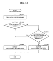
- Fig. 10 is a flow diagram of a process of a repeat-radiograph determination circuit 815.
- the image processing circuit 812 sequentially receives, via a CPU bus 807, the plurality of projection images 601 to 60X processed by a preprocessing circuit 806 under the control of a CPU 808.
- the image processing circuit 812 extracts body-movement information of a subject to be inspected during CT scanning (step S901).
- the body-movement information presentation circuit 814 displays all the body movement information, some of the body movement information of the subject, or statistics of the information on a display monitor 811 (step S902).
- the repeat-radiograph determination circuit 815 determines whether or not a repeat radiograph is required based on the body movement information and an operator's decision (step S903).
- a CT reconstruction circuit 816 reconstructs CT images 701 to 70Y from the projection images 601 to 60X (step S905). If it is determined that a repeat radiograph is necessary, the image processing circuit 812 instructs re-radiographing (step S906) and the process is completed.
- the body-movement information presentation circuit 814 displays the received body-movement information on the display monitor 811. For example, all the information may be displayed in the form of a list, or only items that satisfy a predetermined criterion may be extracted and displayed. Alternatively, statistics calculated by using statistical techniques may be presented. In this embodiment, a sum of changes in position of the diaphragm is presented.
- the repeat-radiograph determination circuit 815 determines whether or not a repeat radiograph is required based on a received change, namely, a change in position of the diaphragm in each representative image in this embodiment, and a decision of an operator who receives the presentation of the body-movement information. Firstly, the repeat-radiograph determination circuit 815 calculates a sum of changes in position of the diaphragm in the representative images (step S1001). Then, the sum is compared to a predetermined threshold value (step S1002). If the sum is smaller than the threshold value, it is determined that a repeat radiograph is not required (step S1003) and the process is completed.
- step S1004 determines whether or not a repeat radiograph is required based on the presented body-movement information
- step S1003 or step S1006 determines whether or not a repeat radiograph is required based on the presented body-movement information.
- the CT reconstruction circuit 816 reconstructs a CT image at the above-described step S905. Since techniques for generating CT images from projection images using CT reconstruction are well known, a description of the techniques is not included herein.
- the need for a repeat radiograph is determined using projection images, CT reconstruction time, which the known methods require to determine the need for a repeat radiograph, is completely eliminated, thus increasing the throughput of the CT inspection.
- the determination of a repeat radiograph can be made based on a clear criterion.
- the operator can easily determine whether or not a repeat radiograph is required.
- the operator can describe the cause of a previous error to a patient and can advice measures to avoid the error to the patient. As a result, the number of repeat radiographs is reduced, thus increasing the throughput of the CT inspection.
- a CT radiographic apparatus having the same configuration as that of the CT radiographic apparatus 100 in the first embodiment is used.
- the processes of the body-movement information extracting circuit 113 and the repeat-radiograph determination circuit 115 in the image processing circuit 112 are different from those in the first embodiment. Accordingly, only the differences will be described below.
- the image processing circuit 112 sequentially receives projection images. By using the body-movement information extracting circuit 113, the image processing circuit 112 extracts body-movement information of a subject to be inspected during CT scanning (step S201). The repeat-radiograph determination circuit 115 then determines whether or not a repeat radiograph is required (step S203). These methods are different from those in the first embodiment and follow processes shown in Fig. 11.
- steps S1101 to S1105 two projection images are received, and an outline of a subject is extracted from each image.
- any outline extraction method may be used.
- an X-ray beam 102 is significantly attenuated after it penetrates a subject to be inspected 103, such as a human body, the X-ray beam 102 creates an edge having a large difference of pixel value in the vicinity of an outline of the subject in a projection image. Therefore, the outline can be accurately extracted by using various types of basic edge-extraction algorithms.
- a change in position between the outlines extracted at steps S1102 and S1105 is calculated (step S1106).
- a projection image is divided into N-by-N blocks (for example, 8-by-8 blocks).
- An amount of movement is calculated by a position alignment process only for a block from which the outline is extracted. The amounts of movement are added and defined as a change in position of the outline between the projection images. Since the (I-1)th projection image and the Ith projection image are taken from different angles, a change in position of the outline is not necessarily zero even though the subject does not move at all. However, in general, since thousands of projection images are taken per rotation during CT scanning, a change in position of the outline between two adjacent images should be extremely small if the subject does not move.
- step S1107 it is determined whether the change in position of the outline calculated at step S1106 exceeds a predetermined threshold value.
- a change in position of the outline is obtained in advance in the case of a completely stationary subject, such as a human body phantom. In this embodiment, 120% of the change that is calculated using a human body phantom is used as the threshold value.
- the image processing circuit 112 receives the next projection image and the same process as described above is repeated (steps S1108 and S1109). If all the projection images are received and the change in position of outline between the (I-1)th projection image and the Ith projection image does not exceed the threshold value, it is determined, at step S1110, that a repeat radiograph is not required, and the process is completed.
- step S1111 If, however, the change in position of the outline between the (I-1)th projection image and the Ith projection image exceeds the threshold value, it is determined, at step S1111, that a repeat radiograph is required.
- the image processing circuit 112 instructs that the radiographing be immediately stopped (step S1112), and the process is completed.
- steps S205 and S206 are the same as those in the first embodiment. Accordingly, descriptions thereof are not included herein.
- the need to repeat a radiograph is determined using projection images, CT reconstruction time, which the known methods require to determine the need for a repeat radiograph, is completely eliminated, thus increasing the throughput of the CT inspection. Additionally, the determination of a repeat radiograph can be performed based on a clear criterion. Furthermore, since the determination of a repeat radiograph can be automatically made, the workload of the operator can be reduced. Furthermore, since the radiographing is stopped immediately after a body movement is detected, unnecessary exposure of the subject to radiation can be reduced.
- operations from emission of an X-ray beam 102 to transmission of projection images are repeated while the rotating unit 120 operates.
- the projection images taken from different angles are sequentially transferred to the image processing circuit 112.
- the data collection circuit 105 receives angle information during a radiographic period from the rotating unit 120 and transmits the angle information and the corresponding projection image to the image processing circuit 112.
- the image processing circuit 112 sequentially receives the projection images and the corresponding angle information. By using the body-movement information extracting circuit 113, the image processing circuit 112 extracts body-movement information of a subject to be inspected during CT scanning (step S201). The repeat-radiograph determination circuit 115 then determines whether or not a repeat radiograph is required (step S203). These methods are different from those in the first embodiment and follow processes shown in Fig. 13.
- a shot angle at radiograph start time is 0 degree
- the value of R must be chosen so as to satisfy the inequality 0 ⁇ R ⁇ 180 for a full-scan (radiographs are taken from 360 degrees, i.e., during one rotation), and 0 ⁇ R ⁇ fan-angle of X-ray projection for a half-scan (radiographs are taken from 180 degrees, i.e., during a half rotation).
- the shot angle at radiograph start time is set to 0 degree and R is also set to 0 degree.
- a reception process is repeated until a projection image taken at an angle of R+180 degrees (hereinafter referred to as a "projection image (R+180)”) is received (steps S1303 and S1304).
- a projection image taken at an angle of R+180 degrees hereinafter referred to as a "projection image (R+180)”
- step S1305 Upon receipt of the projection image (R+180), at step S1305, a reverse image of the projection image (R+180) (hereinafter referred to as a "reverse image (R+180)”) is created.
- a reverse image of the projection image (R+180) hereinafter referred to as a "reverse image (R+180)
- a mirror reversed image is created.
- a difference image between the projection image (R) and the reverse image (R+180) is created (step S1306).
- Absolute pixel values of all pixels of the difference image are added (step S1307).
- the X-ray beams are not parallel over the entire surface of the X-ray sensor.
- the sum In consideration of variation in output level of the X-ray beam and scattered radiation, the sum generally exhibits a certain value although the subject is stationary. Therefore, at step S1308, the sum is evaluated using some threshold value that is determined after considering these factors.
- the predetermined threshold value for example, a human body phantom is used, as in the third embodiment.
- the need for a repeat radiograph is determined using projection images, CT reconstruction time, which the known methods require to determine the need to repeat a radiograph, is completely eliminated, thus increasing the throughput of the CT inspection. Additionally, the need to repeat a radiograph can be determined based on a clear criterion. Furthermore, since the need for a repeat radiograph can be automatically determined, the workload of the operator can be reduced. Furthermore, since a body movement is determined by simple error-free processes, such as reverse image creation, difference image creation, and a thresholding process, the determination is advantageously reliable and accurate for various types of subjects. Also these simple processes advantageously decrease determination time and the load of the radiographic apparatus.
- a radiation image processing apparatus As described above, according to the present invention, a radiation image processing apparatus, a radiation image processing method, a program, and a computer-readable medium, all of which reduce the effect of a body movement, can be provided.
- the object of the present invention is also achieved by providing a storage medium that stores software (a program) that achieves the functions of the apparatus or system described in the first embodiment to the fourth embodiment to the apparatus or system and by causing a computer (for example, a CPU or a MPU) to read and execute the program stored in the storage medium.
- software a program
- a computer for example, a CPU or a MPU
- the program itself read from the storage medium achieves the functions described in the first embodiment to the fourth embodiment.
- a storage medium that stores the program and the program itself achieve the present invention.
- the storage medium that provides the program includes a ROM, a floppy (trademark) disk, a hard disk, an optical disk, a magneto optical disk, a CD-ROM, a CD-R, a magnetic tape, and a nonvolatile memory card.
- embodiments of the present invention include not only the case where a program read from a storage medium achieves the functions described in the first embodiment to the fourth embodiment, but also the case where an OS running on a computer executes some of or all functions described in the first embodiment to the fourth embodiment.
- embodiments of the present invention include the case where, after a program read from a storage medium is stored in an add-on expansion board inserted in a computer or a memory of an add-on expansion board connected to a computer, the add-on expansion board or a CPU in the add-on expansion board executes some of or all functions described in the first embodiment to the fourth embodiment.
- the program includes, for example, program code that corresponds to a flow chart shown in the above-described Fig. 2, 3, 5, 9, 10, 11, or 13.
Applications Claiming Priority (2)
| Application Number | Priority Date | Filing Date | Title |
|---|---|---|---|
| JP2003375463A JP4110074B2 (ja) | 2003-11-05 | 2003-11-05 | 放射線画像処理装置、放射線画像処理方法、プログラム及びコンピュータ可読媒体 |
| JP2003375463 | 2003-11-05 |
Publications (3)
| Publication Number | Publication Date |
|---|---|
| EP1530162A2 true EP1530162A2 (de) | 2005-05-11 |
| EP1530162A3 EP1530162A3 (de) | 2005-10-12 |
| EP1530162B1 EP1530162B1 (de) | 2007-10-24 |
Family
ID=34431273
Family Applications (1)
| Application Number | Title | Priority Date | Filing Date |
|---|---|---|---|
| EP04025802A Expired - Fee Related EP1530162B1 (de) | 2003-11-05 | 2004-10-29 | Vorrichtung, Verfahren, Programm und maschinenlesbares Speichermedium zur Strahlungsbildverarbeitung |
Country Status (4)
| Country | Link |
|---|---|
| US (1) | US7327823B2 (de) |
| EP (1) | EP1530162B1 (de) |
| JP (1) | JP4110074B2 (de) |
| DE (1) | DE602004009653T2 (de) |
Cited By (6)
| Publication number | Priority date | Publication date | Assignee | Title |
|---|---|---|---|---|
| EP1768069A1 (de) * | 2005-09-26 | 2007-03-28 | Canon Kabushiki Kaisha | Verfahren und Vorrichtung zur Verarbeitung von Röntgenbildern |
| EP1913869A2 (de) * | 2006-10-19 | 2008-04-23 | Esaote S.p.A. | Diagnostisches Verfahren und Gerät zur Abbildung des Beckenbodens |
| EP2105093A1 (de) * | 2008-03-27 | 2009-09-30 | Fujifilm Corporation | Strahlungsbilderfassungssystem, Steuerung, Programm und Strahlungsbilderfassungsverfahren |
| EP2653105A1 (de) * | 2010-09-08 | 2013-10-23 | Fujifilm Corporation | Vorrichtung und Verfahren zur Körperbewegungserkennung sowie Röntgenbildgebungsvorrichtung und -verfahren |
| WO2015111052A1 (en) * | 2014-01-23 | 2015-07-30 | Yissum Research Development Company Of The Hebrew University Of Jerusalem Ltd. | Method of repeat computer tomography scanning and system thereof |
| WO2016039886A1 (en) * | 2014-09-09 | 2016-03-17 | General Electric Company | Multiple frame acquisition for exposure control in x-ray medical imagers |
Families Citing this family (17)
| Publication number | Priority date | Publication date | Assignee | Title |
|---|---|---|---|---|
| US7099431B2 (en) * | 2003-06-09 | 2006-08-29 | Canon Kabushiki Kaisha | Radiation imaging apparatus |
| JP4438053B2 (ja) * | 2004-05-11 | 2010-03-24 | キヤノン株式会社 | 放射線撮像装置、画像処理方法及びコンピュータプログラム |
| JP2008228829A (ja) * | 2007-03-16 | 2008-10-02 | Rigaku Corp | 周期的運動の同期算出装置および周期的運動の同期算出方法 |
| JP2009045092A (ja) * | 2007-08-13 | 2009-03-05 | Canon Inc | Ct撮影装置及びその制御方法 |
| JP5400358B2 (ja) * | 2008-11-13 | 2014-01-29 | 富士フイルム株式会社 | 放射線断層撮影装置 |
| JP2010131044A (ja) * | 2008-12-02 | 2010-06-17 | Aloka Co Ltd | X線画像形成装置 |
| JP2010158298A (ja) * | 2009-01-06 | 2010-07-22 | Fujifilm Corp | 断層撮影装置及び断層撮影方法 |
| JP2010187774A (ja) * | 2009-02-16 | 2010-09-02 | Fujifilm Corp | X線画像処理方法、x線画像処理装置、プログラムおよびx線画像撮影装置 |
| JP2010187827A (ja) * | 2009-02-17 | 2010-09-02 | Fujifilm Corp | X線画像処理方法、x線画像処理装置、プログラムおよびx線画像撮影装置 |
| JP6164842B2 (ja) * | 2009-04-17 | 2017-07-19 | コーニンクレッカ フィリップス エヌ ヴェKoninklijke Philips N.V. | 造影剤ベースの撮像 |
| WO2014203938A1 (ja) * | 2013-06-18 | 2014-12-24 | キヤノン株式会社 | トモシンセシス撮影の制御装置、撮影装置、撮影システム、制御方法および当該制御方法をコンピュータに実行させるためのプログラム |
| JP6381198B2 (ja) * | 2013-11-08 | 2018-08-29 | キヤノン株式会社 | 制御装置、制御方法及びプログラム |
| JP7022584B2 (ja) | 2017-12-27 | 2022-02-18 | キヤノン株式会社 | 放射線撮影装置、画像処理装置及び画像判定方法 |
| US10776923B2 (en) * | 2018-06-21 | 2020-09-15 | International Business Machines Corporation | Segmenting irregular shapes in images using deep region growing |
| US10643092B2 (en) | 2018-06-21 | 2020-05-05 | International Business Machines Corporation | Segmenting irregular shapes in images using deep region growing with an image pyramid |
| JP7122886B2 (ja) | 2018-06-25 | 2022-08-22 | 富士フイルム株式会社 | 撮影制御装置、方法およびプログラム |
| JP6607650B2 (ja) * | 2018-10-11 | 2019-11-20 | 国立研究開発法人量子科学技術研究開発機構 | 画像処理装置、放射線治療装置及びプログラム |
Citations (1)
| Publication number | Priority date | Publication date | Assignee | Title |
|---|---|---|---|---|
| US4858128A (en) * | 1986-08-11 | 1989-08-15 | General Electric Company | View-to-view image correction for object motion |
Family Cites Families (7)
| Publication number | Priority date | Publication date | Assignee | Title |
|---|---|---|---|---|
| JPH0616099B2 (ja) * | 1989-02-07 | 1994-03-02 | 浜松ホトニクス株式会社 | Ct装置におけるデータ補正装置 |
| JP4143149B2 (ja) | 1997-11-20 | 2008-09-03 | キヤノン株式会社 | 領域抽出装置、領域抽出方法及びコンピュータ読み取り可能な記録媒体 |
| JP2002365239A (ja) | 2001-06-05 | 2002-12-18 | Shimadzu Corp | コーンビームct装置 |
| DE10140740C1 (de) * | 2001-08-20 | 2003-04-17 | Siemens Ag | Verfahren zum Abtasten eines Untersuchungsobjekts mittels eines Computer-Tomographiegeräts sowie Computer-Tomographiegerät |
| JP4416471B2 (ja) * | 2003-10-17 | 2010-02-17 | キヤノン株式会社 | デジタルx線画像撮影装置及びその駆動制御プログラム |
| JP2005176896A (ja) * | 2003-12-16 | 2005-07-07 | Canon Inc | X線画像処理装置、x線画像処理方法、プログラム及びコンピュータ可読記憶媒体 |
| US7782998B2 (en) * | 2004-12-21 | 2010-08-24 | General Electric Company | Method and apparatus for correcting motion in image reconstruction |
-
2003
- 2003-11-05 JP JP2003375463A patent/JP4110074B2/ja not_active Expired - Lifetime
-
2004
- 2004-10-22 US US10/969,876 patent/US7327823B2/en active Active
- 2004-10-29 DE DE602004009653T patent/DE602004009653T2/de active Active
- 2004-10-29 EP EP04025802A patent/EP1530162B1/de not_active Expired - Fee Related
Patent Citations (1)
| Publication number | Priority date | Publication date | Assignee | Title |
|---|---|---|---|---|
| US4858128A (en) * | 1986-08-11 | 1989-08-15 | General Electric Company | View-to-view image correction for object motion |
Non-Patent Citations (1)
| Title |
|---|
| KAKADIARIS I ET AL: "Inferring 2D Object Structure from the Deformation of Apparent Contours" COMPUTER VISION AND IMAGE UNDERSTANDING, ACADEMIC PRESS, SAN DIEGO, CA, US, vol. 65, no. 2, February 1997 (1997-02), pages 129-147, XP004464103 ISSN: 1077-3142 * |
Cited By (13)
| Publication number | Priority date | Publication date | Assignee | Title |
|---|---|---|---|---|
| EP1768069A1 (de) * | 2005-09-26 | 2007-03-28 | Canon Kabushiki Kaisha | Verfahren und Vorrichtung zur Verarbeitung von Röntgenbildern |
| CN1939219B (zh) * | 2005-09-26 | 2011-01-12 | 佳能株式会社 | 处理放射线图像的方法以及处理设备 |
| US8457710B2 (en) | 2006-10-19 | 2013-06-04 | Esaote S.P.A. | Diagnostic imaging method and apparatus for the anatomical region of the pelvic floor |
| EP1913869A2 (de) * | 2006-10-19 | 2008-04-23 | Esaote S.p.A. | Diagnostisches Verfahren und Gerät zur Abbildung des Beckenbodens |
| EP1913869A3 (de) * | 2006-10-19 | 2008-12-10 | Esaote S.p.A. | Diagnostisches Verfahren und Gerät zur Abbildung des Beckenbodens |
| EP2105093A1 (de) * | 2008-03-27 | 2009-09-30 | Fujifilm Corporation | Strahlungsbilderfassungssystem, Steuerung, Programm und Strahlungsbilderfassungsverfahren |
| US7923687B2 (en) | 2008-03-27 | 2011-04-12 | Fujifilm Corporation | Radiation image capturing system, controller, program, and radiation image capturing method |
| EP2653105A1 (de) * | 2010-09-08 | 2013-10-23 | Fujifilm Corporation | Vorrichtung und Verfahren zur Körperbewegungserkennung sowie Röntgenbildgebungsvorrichtung und -verfahren |
| EP2659837A1 (de) * | 2010-09-08 | 2013-11-06 | Fujifilm Corporation | Vorrichtung und Verfahren zur Körperbewegungserkennung sowie Röntgenbildgebungsvorrichtung und -verfahren |
| WO2015111052A1 (en) * | 2014-01-23 | 2015-07-30 | Yissum Research Development Company Of The Hebrew University Of Jerusalem Ltd. | Method of repeat computer tomography scanning and system thereof |
| WO2016039886A1 (en) * | 2014-09-09 | 2016-03-17 | General Electric Company | Multiple frame acquisition for exposure control in x-ray medical imagers |
| US9526468B2 (en) | 2014-09-09 | 2016-12-27 | General Electric Company | Multiple frame acquisition for exposure control in X-ray medical imagers |
| EP3922182A1 (de) * | 2014-09-09 | 2021-12-15 | General Electric Company | Aufnahme mehrerer einzelbilder zur belichtungssteuerung bei medizinischen röntgenbildgebern |
Also Published As
| Publication number | Publication date |
|---|---|
| JP4110074B2 (ja) | 2008-07-02 |
| US20050111614A1 (en) | 2005-05-26 |
| EP1530162A3 (de) | 2005-10-12 |
| DE602004009653D1 (de) | 2007-12-06 |
| US7327823B2 (en) | 2008-02-05 |
| JP2005137472A (ja) | 2005-06-02 |
| EP1530162B1 (de) | 2007-10-24 |
| DE602004009653T2 (de) | 2008-08-28 |
Similar Documents
| Publication | Publication Date | Title |
|---|---|---|
| EP1530162B1 (de) | Vorrichtung, Verfahren, Programm und maschinenlesbares Speichermedium zur Strahlungsbildverarbeitung | |
| CN109561869B (zh) | 用于计算机断层扫描的方法和系统 | |
| US10952694B2 (en) | Method and apparatus for correcting computed tomography image | |
| US9498180B2 (en) | Detecting and quantifying patient motion during tomosynthesis scans | |
| JP4438053B2 (ja) | 放射線撮像装置、画像処理方法及びコンピュータプログラム | |
| JP4928106B2 (ja) | Ct撮影装置 | |
| JP2004121853A (ja) | トランケーション補償の方法及び装置 | |
| US10410381B2 (en) | Method and apparatus for processing tomographic image | |
| CN107945850B (zh) | 用于处理医学图像的方法和装置 | |
| KR101665513B1 (ko) | 컴퓨터 단층 촬영 장치 및 그에 따른 ct 영상 복원 방법 | |
| KR20060061249A (ko) | 선량 평가 방법 및 x선 ct 장치 | |
| KR101946576B1 (ko) | 의료 영상 장치 및 의료 영상 처리 방법 | |
| US8559758B2 (en) | Apparatus for determining a modification of a size of an object | |
| US20200226800A1 (en) | Tomographic imaging apparatus and method of generating tomographic image | |
| JPH10225452A (ja) | 部分体積アーチファクトを検出する方法およびシステム | |
| JPH10225453A (ja) | 計算機式断層写真法システムにおいて基準チャンネルの閉塞を検出する方法及びシステム | |
| JP5038852B2 (ja) | 断層像処理方法、断層像処理装置、断層像処理プログラム、およびx線ct装置 | |
| US20100254585A1 (en) | Overexposure correction for large volume reconstruction in computed tomography apparatus | |
| US20180139467A1 (en) | Medical imaging apparatus, medical image processing method, and computer-readable recording medium related to the medical image processing method | |
| US20050018889A1 (en) | Systems and methods for filtering images | |
| JP6642048B2 (ja) | 医療画像表示システム、医療画像表示プログラム及び医療画像表示方法 | |
| US7263155B2 (en) | Radiography apparatus and radiation image processing method | |
| JP2006000223A (ja) | X線ct装置 | |
| JP2004336662A (ja) | 画像処理装置及び方法 | |
| JP2004254932A (ja) | X線ct装置 |
Legal Events
| Date | Code | Title | Description |
|---|---|---|---|
| PUAI | Public reference made under article 153(3) epc to a published international application that has entered the european phase |
Free format text: ORIGINAL CODE: 0009012 |
|
| AK | Designated contracting states |
Kind code of ref document: A2 Designated state(s): AT BE BG CH CY CZ DE DK EE ES FI FR GB GR HU IE IT LI LU MC NL PL PT RO SE SI SK TR |
|
| AX | Request for extension of the european patent |
Extension state: AL HR LT LV MK |
|
| PUAL | Search report despatched |
Free format text: ORIGINAL CODE: 0009013 |
|
| AK | Designated contracting states |
Kind code of ref document: A3 Designated state(s): AT BE BG CH CY CZ DE DK EE ES FI FR GB GR HU IE IT LI LU MC NL PL PT RO SE SI SK TR |
|
| AX | Request for extension of the european patent |
Extension state: AL HR LT LV MK |
|
| RIC1 | Information provided on ipc code assigned before grant |
Ipc: 7G 06T 11/00 A Ipc: 7G 06T 7/00 B |
|
| 17P | Request for examination filed |
Effective date: 20060412 |
|
| AKX | Designation fees paid |
Designated state(s): DE FR GB IT NL |
|
| 17Q | First examination report despatched |
Effective date: 20060630 |
|
| GRAP | Despatch of communication of intention to grant a patent |
Free format text: ORIGINAL CODE: EPIDOSNIGR1 |
|
| GRAS | Grant fee paid |
Free format text: ORIGINAL CODE: EPIDOSNIGR3 |
|
| GRAA | (expected) grant |
Free format text: ORIGINAL CODE: 0009210 |
|
| AK | Designated contracting states |
Kind code of ref document: B1 Designated state(s): DE FR GB IT NL |
|
| REG | Reference to a national code |
Ref country code: GB Ref legal event code: FG4D |
|
| RIN1 | Information on inventor provided before grant (corrected) |
Inventor name: MATSUURA, TOMOHIKO,C/O CANON KABUSHIKI KAISHA |
|
| REF | Corresponds to: |
Ref document number: 602004009653 Country of ref document: DE Date of ref document: 20071206 Kind code of ref document: P |
|
| EN | Fr: translation not filed | ||
| PLBE | No opposition filed within time limit |
Free format text: ORIGINAL CODE: 0009261 |
|
| STAA | Information on the status of an ep patent application or granted ep patent |
Free format text: STATUS: NO OPPOSITION FILED WITHIN TIME LIMIT |
|
| 26N | No opposition filed |
Effective date: 20080725 |
|
| PG25 | Lapsed in a contracting state [announced via postgrant information from national office to epo] |
Ref country code: FR Free format text: LAPSE BECAUSE OF FAILURE TO SUBMIT A TRANSLATION OF THE DESCRIPTION OR TO PAY THE FEE WITHIN THE PRESCRIBED TIME-LIMIT Effective date: 20080808 |
|
| PG25 | Lapsed in a contracting state [announced via postgrant information from national office to epo] |
Ref country code: FR Free format text: LAPSE BECAUSE OF FAILURE TO SUBMIT A TRANSLATION OF THE DESCRIPTION OR TO PAY THE FEE WITHIN THE PRESCRIBED TIME-LIMIT Effective date: 20071031 |
|
| PG25 | Lapsed in a contracting state [announced via postgrant information from national office to epo] |
Ref country code: IT Free format text: LAPSE BECAUSE OF NON-PAYMENT OF DUE FEES Effective date: 20071031 |
|
| PGFP | Annual fee paid to national office [announced via postgrant information from national office to epo] |
Ref country code: NL Payment date: 20201027 Year of fee payment: 17 |
|
| PGFP | Annual fee paid to national office [announced via postgrant information from national office to epo] |
Ref country code: GB Payment date: 20201027 Year of fee payment: 17 |
|
| PGFP | Annual fee paid to national office [announced via postgrant information from national office to epo] |
Ref country code: DE Payment date: 20201228 Year of fee payment: 17 |
|
| REG | Reference to a national code |
Ref country code: DE Ref legal event code: R119 Ref document number: 602004009653 Country of ref document: DE |
|
| REG | Reference to a national code |
Ref country code: NL Ref legal event code: MM Effective date: 20211101 |
|
| GBPC | Gb: european patent ceased through non-payment of renewal fee |
Effective date: 20211029 |
|
| PG25 | Lapsed in a contracting state [announced via postgrant information from national office to epo] |
Ref country code: NL Free format text: LAPSE BECAUSE OF NON-PAYMENT OF DUE FEES Effective date: 20211101 Ref country code: GB Free format text: LAPSE BECAUSE OF NON-PAYMENT OF DUE FEES Effective date: 20211029 Ref country code: DE Free format text: LAPSE BECAUSE OF NON-PAYMENT OF DUE FEES Effective date: 20220503 |