EP1526239B1 - Fermeture de sécurité magnétique pour un dispositif de protection mobile - Google Patents
Fermeture de sécurité magnétique pour un dispositif de protection mobile Download PDFInfo
- Publication number
- EP1526239B1 EP1526239B1 EP20040024134 EP04024134A EP1526239B1 EP 1526239 B1 EP1526239 B1 EP 1526239B1 EP 20040024134 EP20040024134 EP 20040024134 EP 04024134 A EP04024134 A EP 04024134A EP 1526239 B1 EP1526239 B1 EP 1526239B1
- Authority
- EP
- European Patent Office
- Prior art keywords
- protection device
- housing
- closure according
- sensor
- magnet
- Prior art date
- Legal status (The legal status is an assumption and is not a legal conclusion. Google has not performed a legal analysis and makes no representation as to the accuracy of the status listed.)
- Expired - Lifetime
Links
- 230000000977 initiatory effect Effects 0.000 claims 1
- 230000001681 protective effect Effects 0.000 description 31
- 235000014676 Phragmites communis Nutrition 0.000 description 2
- 229920003023 plastic Polymers 0.000 description 2
- 230000002411 adverse Effects 0.000 description 1
- 230000001934 delay Effects 0.000 description 1
- 230000001419 dependent effect Effects 0.000 description 1
- 238000004519 manufacturing process Methods 0.000 description 1
- 239000000126 substance Substances 0.000 description 1
- 230000001960 triggered effect Effects 0.000 description 1
Images


Classifications
-
- E—FIXED CONSTRUCTIONS
- E05—LOCKS; KEYS; WINDOW OR DOOR FITTINGS; SAFES
- E05C—BOLTS OR FASTENING DEVICES FOR WINGS, SPECIALLY FOR DOORS OR WINDOWS
- E05C19/00—Other devices specially designed for securing wings, e.g. with suction cups
- E05C19/16—Devices holding the wing by magnetic or electromagnetic attraction
-
- E—FIXED CONSTRUCTIONS
- E05—LOCKS; KEYS; WINDOW OR DOOR FITTINGS; SAFES
- E05B—LOCKS; ACCESSORIES THEREFOR; HANDCUFFS
- E05B17/00—Accessories in connection with locks
- E05B17/0025—Devices for forcing the wing firmly against its seat or to initiate the opening of the wing
- E05B17/0033—Devices for forcing the wing firmly against its seat or to initiate the opening of the wing for opening only
-
- Y—GENERAL TAGGING OF NEW TECHNOLOGICAL DEVELOPMENTS; GENERAL TAGGING OF CROSS-SECTIONAL TECHNOLOGIES SPANNING OVER SEVERAL SECTIONS OF THE IPC; TECHNICAL SUBJECTS COVERED BY FORMER USPC CROSS-REFERENCE ART COLLECTIONS [XRACs] AND DIGESTS
- Y10—TECHNICAL SUBJECTS COVERED BY FORMER USPC
- Y10S—TECHNICAL SUBJECTS COVERED BY FORMER USPC CROSS-REFERENCE ART COLLECTIONS [XRACs] AND DIGESTS
- Y10S292/00—Closure fasteners
- Y10S292/71—Refrigerator latches
-
- Y—GENERAL TAGGING OF NEW TECHNOLOGICAL DEVELOPMENTS; GENERAL TAGGING OF CROSS-SECTIONAL TECHNOLOGIES SPANNING OVER SEVERAL SECTIONS OF THE IPC; TECHNICAL SUBJECTS COVERED BY FORMER USPC CROSS-REFERENCE ART COLLECTIONS [XRACs] AND DIGESTS
- Y10—TECHNICAL SUBJECTS COVERED BY FORMER USPC
- Y10T—TECHNICAL SUBJECTS COVERED BY FORMER US CLASSIFICATION
- Y10T292/00—Closure fasteners
- Y10T292/11—Magnetic
-
- Y—GENERAL TAGGING OF NEW TECHNOLOGICAL DEVELOPMENTS; GENERAL TAGGING OF CROSS-SECTIONAL TECHNOLOGIES SPANNING OVER SEVERAL SECTIONS OF THE IPC; TECHNICAL SUBJECTS COVERED BY FORMER USPC CROSS-REFERENCE ART COLLECTIONS [XRACs] AND DIGESTS
- Y10—TECHNICAL SUBJECTS COVERED BY FORMER USPC
- Y10T—TECHNICAL SUBJECTS COVERED BY FORMER US CLASSIFICATION
- Y10T292/00—Closure fasteners
- Y10T292/57—Operators with knobs or handles
Definitions
- the invention relates to a magnetic security closure for a movable protective device according to the preamble of claim 1.
- the object of the invention is to provide a magnetic security closure for a movable protective device according to the preamble of claim 1, wherein its functionality is not affected by a distortion of the protective device.
- a sensor responsible for detecting the closed and opened condition of the guard in particular a safety sensor, is positioned in the immediate vicinity of the guard locking means, i. integrated into the locking device.
- delays of the protective devices can not adversely affect.
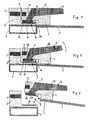
- a frame 1 shown here by way of example from a box-shaped profile, a fixed part in the form of a fencing, a housing or the like. provided, which receives a pivotable protective device 2 in the form of a door or flap, which is articulated on the side of the frame 1, not shown about hinges.
- a housing 3 On the protective device 2, a housing 3 is mounted, which carries a handle 4 for opening and closing the protective device 2, which is pivotable about an axis 5 relative to the housing 3.
- a sensor housing 6 is mounted on the frame 1, which receives a sensor 7, which serves to determine the closed or opened state of the protective device 2.
- the sensor 7 is actuated via a triggering device 8, which is received by the mounted on the protective device 2 housing 3, respectively.
- the triggering device 8 is the sensor 7 opposite.
- the sensor 7 may be an electronic sensor which cooperates with a TAG as the triggering device 8, but it may also consist of one or more reed contacts which can be triggered by magnets as the triggering device 8. But it can also be the corresponding contactless proximity switch, photocells or the like. or act around electromechanical sensors. Thus, for example, safety sensors can be used, as described in DE 100 43 237 C1 or DE 103 07 044 A1.
- the housing 3 further has a magnet arrangement 9 with at least one holding magnet 10, while the sensor housing 6 is provided correspondingly with opposite pole plates 11 for the holding magnets 10.
- the holding magnet 10 is located and the associated pole plate 11 opposite, so that an intended holding force for locking the protective device 2 is supplied.
- - Holding magnet 10 and pole plate 11 can of course be reversed housed in the sensor housing 6 and housing 3. Instead of a pole piece 11, a magnet could also be used.
- the handle 4 is as a two-armed lever mounted on the housing 3, wherein an arm 12 of the lever faces the sensor housing 6 and separates with its free end when pivoting to open the protective device 2, the holding magnets 10 of the magnet assembly 9 of the associated pole plates 11.
- the handle 4 can be grasped at its other arm 13 and pivoted outwards relative to the protective device 2, cf. Fig. 2, whereby the free end of the arm 12 adjacent to the pole piece 11 or even with the latter itself engages and lifts the holding magnet 10 of its pole plate 11 against the holding force acting therebetween during further pivoting, so that the protection device is opened , see. Fig. 3.
- the force required for opening can be chosen to be much smaller than the clamping force of the magnetic device 9.
- a stop 14 is disposed adjacent to the magnet assembly 9, wherein at least one pole piece 11 is movable in the direction of the magnet assembly 9 according to a predetermined game at the same time.
- the latter leads to a secure contact between the holding magnet 10 and the pole plate 11 in the closed state of the protective device 2, while the stop 14 prevents when closing, that the energy of the closing and an associated impact is transmitted to the magnetic device 9.
- the pole plates 11 which are movable in this way also allow a certain oblique position of the protective device 2.
- the housing 3 and the sensor housing 6 are each formed angularly, so that they overlap correspondingly in the region of the magnet assembly 9 in the closed state of the protective device 2, such as a revolving door or flap.
- the handle 4 is mounted with its axis 5 in its extension 15 extending over the sensor housing 6.
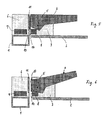
- the handle 4 engages around the housing 3 fork-shaped (or vice versa) and is provided at the end of his arm 13 with an engagement recess 16.
- the extension 15 is located on both sides in each case a holding magnet 10 which protrudes on the pole plates 11 facing side of the extension 15, and adjacent to the end face of the extension 15, the triggering device 8 in the form of a holder 17 with two tripping magnets 18 for reed contacts Sensor 7 in the sensor housing 6 (the latter in Fig. 4 not shown).
- the sensor housing 6 receives the pole plates 11 with lateral and vertical clearance below housing openings 19.
- the sensor housing 6 also accommodates a circuit board 20.
- FIG. 5 is one for a protective device 2 in the form of a sliding door or sliding flap.
- the housing 3 and the sensor housing 6 are cuboid, wherein the magnet assembly 9 is mounted such that the applied magnetic force acts perpendicular to the direction of the protective device 2.
- the holding magnet 10 is separated from its pole plate 11 and the protective device can be pushed open.
- the lever may also be expedient for the lever to be pivotable in the direction of opening.
- the axis 5 only to be offset accordingly upwards.
- the housing 3 and the sensor housing 6 are provided with mutually facing inclined surfaces 21, 22, so that the housing 3, the sensor housing 6 on the frame 1 partially overlaps, wherein between the inclined surfaces 21, 22, a gap which is characterized by the fact that adjacent to the inclined surfaces 21, 22 of the at least one holding magnet 10 and the associated pole plate 11 are respectively arranged, can be bridged by the magnetic device 9.
- the sensor 7 and the triggering device 8 are adjacent to the inclined surfaces 21, 22.
- the inclined surfaces 21, 22 have an angle of about 30 to 60 °, in particular about 45 °, to the surface of the protective device 2, so that these by pivoting the Handle 4 - regardless of whether it is a pivotable or a sliding guard 2 - can be opened against the magnetic clamping force.
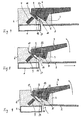
- the holding magnets 9 are not mounted in or on the housing 3, but on the lever itself compared to the embodiment of Fig. 7. By pivoting the lever, the holding magnets 9 are separated from their pole plates 10 so far that the remaining residual magnetic force acting therebetween, readily to open by pivoting a corresponding protective device 2, Fig. 10, or by moving a corresponding protective device 2, Fig. 11, can be overcome.
Landscapes
- Physics & Mathematics (AREA)
- Electromagnetism (AREA)
- Engineering & Computer Science (AREA)
- Mechanical Engineering (AREA)
- Switches That Are Operated By Magnetic Or Electric Fields (AREA)
- Operating, Guiding And Securing Of Roll- Type Closing Members (AREA)
- Lock And Its Accessories (AREA)
Claims (10)
- Fermeture de sécurité magnétique pour un dispositif de protection (2) mobile par rapport à un élément fixe, comprenant un boîtier (3) pouvant être apposé sur le dispositif de protection, avec une poignée (4) permettant d'ouvrir et de fermer le dispositif de protection (2) et un boîtier de capteur (6) pouvant être apposé sur l'élément fixe, comportant un capteur (7) permettant de constater l'état fermé ou ouvert du dispositif de protection (2), pour lequel le boîtier (3) qui se trouve sur le dispositif de protection (2) présente un dispositif de déclenchement (8) pour le capteur (7), lequel fait face au capteur (7) à l'état fermé du dispositif de protection (2), et le boîtier (3) ainsi que le boîtier de capteur (6) présentent, de manière répartie sur ceux-ci, un agencement d'aimants (9) comportant au moins un aimant de maintien (10) et une tôle polarisée (11) associée,
caractérisée en ce que la poignée (4) est un levier à deux bras disposé de manière pivotante sur le boîtier (3), un bras (12) du levier étant orienté vers le boîtier du capteur (6) de sorte que, avec son extrémité libre, lors du pivotement pour l'ouverture du dispositif de protection, le levier sépare le au moins un aimant de maintien (10) de l'agencement d'aimants (9) de sa tôle polarisée associée (11). - Fermeture selon la revendication 1, caractérisée en ce que le au moins un aimant de maintien (10) est maintenu avec un jeu latéral.
- Fermeture selon l'une quelconque des revendications 1 ou 2, caractérisée en ce que le au moins un aimant de maintien (10) est maintenu avec un certain jeu en direction de la tôle polarisée associée (11).
- Fermeture selon l'une quelconque des revendications 1 à 3, caractérisée en ce que, à proximité du au moins un aimant de maintien (10), est disposée une tôle (10a) magnétisable, présentant un surdimensionnement par rapport à l'aimant de maintien (10), avec un certain jeu par rapport à l'aimant de maintien (10).
- Fermeture selon l'une quelconque des revendications 1 à 4, caractérisée en ce que le au moins un aimant de maintien (10) est disposé sur l'axe de rotation (5) du levier.
- Fermeture selon l'une quelconque des revendications 1 à 5, caractérisée en ce que, à proximité de l'agencement d'aimants (9), est disposée une butée (14).
- Fermeture selon l'une quelconque des revendications 1 à 6, caractérisée en ce que le levier permettant d'ouvrir le dispositif de protection (2) peut pivoter pour se rapprocher ou s'éloigner du dispositif de protection (2) avec son bras (13) opposé au boîtier de capteur (6).
- Fermeture selon l'une quelconque des revendications 1 à 7, caractérisée en ce que, entre le boîtier (3) et le boîtier du capteur (6), est prévue une fente s'étendant de manière oblique par rapport au plan du dispositif de protection (2), pouvant être traversée par l'agencement d'aimants (9), de telle sorte que le dispositif de protection (2) avec le boîtier (3) recouvre l'élément fixe.
- Fermeture selon la revendication 8, caractérisée en ce que la fente est oblique selon un angle de 30° à 60°, en particulier environ 45°, par rapport au plan du dispositif de protection (2).
- Fermeture selon l'une quelconque des revendications 1 à 9, caractérisée en ce que le dispositif de protection (2) peut être amené à se déplacer ou à pivoter par rapport à l'élément fixe.
Applications Claiming Priority (2)
| Application Number | Priority Date | Filing Date | Title |
|---|---|---|---|
| DE2003148527 DE10348527B3 (de) | 2003-10-18 | 2003-10-18 | Magnetischer Sicherheitsverschluß für eine bewegliche Schutzeinrichtung |
| DE10348527 | 2003-10-18 |
Publications (2)
| Publication Number | Publication Date |
|---|---|
| EP1526239A1 EP1526239A1 (fr) | 2005-04-27 |
| EP1526239B1 true EP1526239B1 (fr) | 2006-07-19 |
Family
ID=34384375
Family Applications (1)
| Application Number | Title | Priority Date | Filing Date |
|---|---|---|---|
| EP20040024134 Expired - Lifetime EP1526239B1 (fr) | 2003-10-18 | 2004-10-09 | Fermeture de sécurité magnétique pour un dispositif de protection mobile |
Country Status (3)
| Country | Link |
|---|---|
| US (2) | US20050108945A1 (fr) |
| EP (1) | EP1526239B1 (fr) |
| DE (2) | DE10348527B3 (fr) |
Families Citing this family (30)
| Publication number | Priority date | Publication date | Assignee | Title |
|---|---|---|---|---|
| US7784219B2 (en) * | 2004-11-01 | 2010-08-31 | Sharp Kabushiki Kaisha | Door opening and closing mechanism |
| DE202005002960U1 (de) * | 2005-01-21 | 2006-06-01 | Liebherr-Hausgeräte Ochsenhausen GmbH | Kühl- und/oder Gefrierschranktürgriff |
| EP1762679B1 (fr) * | 2005-09-07 | 2016-10-26 | VKR Holding A/S | Dispositif et procédé de verrouillage d'une fenêtre |
| WO2007028590A2 (fr) * | 2005-09-07 | 2007-03-15 | Vkr Holding A/S | Moyens et procedes de fixation d'une fenetre |
| DE102006045073A1 (de) * | 2006-09-21 | 2008-04-10 | Dieter Kemke | Magnetisches Schließsystem sowie Sicherheitstür mit einem magnetischen Schließsystem |
| DE102006061083A1 (de) * | 2006-12-22 | 2008-06-26 | BSH Bosch und Siemens Hausgeräte GmbH | Kältegerät mit Türöffnungshilfe |
| US8939476B2 (en) * | 2009-05-15 | 2015-01-27 | Gordon C. Tang | Easily installed and non-defacing security latch |
| US20100289277A1 (en) * | 2009-05-15 | 2010-11-18 | Tang Gordon C | Easily installed and non-defacing security latch |
| US9657501B2 (en) * | 2009-10-06 | 2017-05-23 | Aasa Abloy Australia Pty Ltd | Electric strike and combination with improved lock assembly |
| US7975837B2 (en) * | 2009-12-11 | 2011-07-12 | Heat And Control, Inc. | Conveyor with safety gate |
| US8699200B2 (en) * | 2010-02-05 | 2014-04-15 | Honeywell International Inc. | Secure non-contact switch |
| US8456792B2 (en) * | 2010-02-05 | 2013-06-04 | Honeywell International Inc. | Secure non-contact switch |
| DE102010012581A1 (de) | 2010-03-23 | 2011-09-29 | Arca Beteiligungen Gmbh | Antriebsanordnung |
| US8552875B2 (en) | 2010-05-28 | 2013-10-08 | Rockwell Automation Technologies, Inc. | Efficient and safe door locking control in power-off and power-on conditions |
| US8525686B2 (en) | 2010-05-28 | 2013-09-03 | Rockwell Automation Technologies, Inc. | Variable adjustable door latch |
| ITRM20120492A1 (it) * | 2012-10-16 | 2014-04-17 | Bitron Spa | Dispositivo blocco-porta. |
| US9347247B2 (en) * | 2013-10-30 | 2016-05-24 | General Electric Company | Latch assembly |
| CN103883174B (zh) * | 2014-03-19 | 2016-02-24 | 广东镖臣防盗设备有限公司 | 双头防振电磁铁装置 |
| DE102015008761B3 (de) * | 2015-07-06 | 2016-11-10 | Cosi Elektronik Gmbh | Magnetischer Sicherheitsverschluss |
| JP6708403B2 (ja) * | 2015-12-10 | 2020-06-10 | キヤノン株式会社 | 画像形成装置 |
| CN105460366B (zh) | 2015-12-28 | 2017-11-21 | 同方威视技术股份有限公司 | 防护装置和包括该防护装置的激光拉曼安检仪 |
| US9926729B2 (en) * | 2016-01-06 | 2018-03-27 | J & S Company Llc | Retractable screen door handle assembly |
| TWI586572B (zh) * | 2016-08-24 | 2017-06-11 | Sunny Wheel Industrial Co Ltd | A magnetic attraction device for use in addition to foot |
| US20180094463A1 (en) * | 2016-10-05 | 2018-04-05 | Huf North America Automotive Parts Mfg. Corp. | Door handle assembly with a magnetic field detector |
| TWI607918B (zh) * | 2016-12-22 | 2017-12-11 | Sunny Wheel Industrial Co Ltd | Magnetic suction mounting device for soil removal |
| US10865050B2 (en) | 2017-08-30 | 2020-12-15 | Honda Motor Co., Ltd. | Manufacturing process switch for triggering an event when opened |
| US11261627B2 (en) * | 2018-08-09 | 2022-03-01 | Kason Industries, Inc. | Magnet latch |
| US10895094B2 (en) * | 2018-09-07 | 2021-01-19 | Consumer 2.0, Inc. | Automated door lock |
| IT201900011694A1 (it) | 2019-07-12 | 2021-01-12 | Pizzato Elettrica Srl | Interruttore di sicurezza con touch panel per il controllo di accessi di macchine o impianti industriali |
| IT202000025354A1 (it) | 2020-10-26 | 2022-04-26 | Pizzato Elettrica Srl | Dispositivo azionatore a maniglia per accessi di macchine o impianti industriali e relativo assieme |
Family Cites Families (13)
| Publication number | Priority date | Publication date | Assignee | Title |
|---|---|---|---|---|
| US2673111A (en) * | 1951-10-20 | 1954-03-23 | Macy O Teetor | Magnetic door catch |
| US3201960A (en) * | 1963-11-19 | 1965-08-24 | Kason Hardware Corp | Combination magnetic and mechanical latch |
| US4904005A (en) * | 1988-11-18 | 1990-02-27 | Harrow Products, Inc. | Entrance security system |
| DE9100626U1 (de) * | 1991-01-19 | 1991-04-11 | H. Kuhnke Gmbh Kg, 2427 Malente | Elektrisch auslösbare Entriegelungsvorrichtung |
| GB9419404D0 (en) * | 1994-09-27 | 1994-11-09 | Nt Security Ltd | Electromagnetic locking devices |
| US5865483A (en) * | 1997-01-16 | 1999-02-02 | Dubravin; Roman | Electromechanical locking system |
| DE19711588A1 (de) * | 1997-03-20 | 1998-09-24 | Euchner Gmbh & Co | Sicherheitsschalter |
| US5883345A (en) | 1997-12-23 | 1999-03-16 | Otis Elevator Company | Sonic position measurement system |
| US6539760B1 (en) * | 1999-05-24 | 2003-04-01 | K.A. Schmersal Gmbh & Co. | Monitoring device |
| WO2002001029A1 (fr) * | 2000-06-29 | 2002-01-03 | Millard, Paul, Stefanus | Dispositif de verrouillage de porte |
| NL1018149C2 (nl) * | 2001-05-25 | 2002-11-26 | Tamar Vanessa Grahmbeek | Stelsel van twee onderling gelijkvormige, platte elementen welke magnetisch kunnen worden gekoppeld, waarbij het stelsel voorzieningen omvat voor ontkoppeling van genoemde elementen door een gebruiker. |
| DE10150463A1 (de) | 2001-10-16 | 2003-04-17 | Hcs Hydraulic Control Systems | Elektronische Einrichtung zur Regelung von Funktionen von hydraulischen und elektrischen Aufzügen |
| US6758504B2 (en) * | 2002-08-30 | 2004-07-06 | Michael C. Mandall | Electromagnetic door lock |
-
2003
- 2003-10-18 DE DE2003148527 patent/DE10348527B3/de not_active Expired - Fee Related
-
2004
- 2004-10-09 EP EP20040024134 patent/EP1526239B1/fr not_active Expired - Lifetime
- 2004-10-09 DE DE200450000980 patent/DE502004000980D1/de not_active Expired - Lifetime
- 2004-10-12 US US10/964,202 patent/US20050108945A1/en not_active Abandoned
-
2006
- 2006-11-01 US US11/555,627 patent/US7377560B2/en not_active Expired - Fee Related
Also Published As
| Publication number | Publication date |
|---|---|
| EP1526239A1 (fr) | 2005-04-27 |
| US20050108945A1 (en) | 2005-05-26 |
| DE10348527B3 (de) | 2005-08-18 |
| DE502004000980D1 (de) | 2006-08-31 |
| US7377560B2 (en) | 2008-05-27 |
| US20070096856A1 (en) | 2007-05-03 |
Similar Documents
| Publication | Publication Date | Title |
|---|---|---|
| EP1526239B1 (fr) | Fermeture de sécurité magnétique pour un dispositif de protection mobile | |
| DE2914565C2 (de) | Schloß für Kraftfahrzeugtüren mit Anzeige des Verschlußzustandes | |
| EP3908728B1 (fr) | Serrure de véhicule à moteur | |
| EP2011935A1 (fr) | Fermeture à levier pivotant dotée d'un levier de saisie verrouillable électriquement | |
| DE4129706A1 (de) | Elektromotorischer aktuator, insbesondere fuer eine zentrale tuerverriegelungsanlage eines kraftfahrzeugs | |
| EP4041969B1 (fr) | Armoire de commande pourvue d'une porte d'armoire de commande présentant un capteur d'état de porte | |
| DE69926455T2 (de) | Schlüsselsicherheitsschalter | |
| EP2486207B1 (fr) | Dispositif de deverrouillage | |
| DE112006000426B4 (de) | Sicherheitsschalter | |
| EP1071214B1 (fr) | Dispositif de surveillance | |
| EP1632921B1 (fr) | Avertisseur de danger manuel | |
| EP2933404A1 (fr) | Ouverture de porte comprenant un contact de retour d'information | |
| DE10339363B4 (de) | Zugangsschutzeinrichtung für einen Raumbereich | |
| EP2787110A1 (fr) | Verrou de porte pour appareils électroménagers | |
| EP2284432B1 (fr) | Dispositif de surveillance d'un état d'un dispositif relevant de la sécurité | |
| DE20208183U1 (de) | Vorrichtung zur Sicherung von Notausgangstüren | |
| EP3670794A1 (fr) | Agencement de porte et procédé de fonctionnement d'un agencement de porte | |
| DE29824200U1 (de) | Schutzvorrichtung | |
| DE10307043B4 (de) | Sicherheitsverriegelung | |
| DE29919268U1 (de) | Ladevorrichtung | |
| DE4335569A1 (de) | Sicherungsvorrichtung für Tore oder dergleichen | |
| DE19609016C2 (de) | Sicherheitsvorrichtung für eine Druckmaschine | |
| AT506943B1 (de) | Schutzeinrichtung für eine spritzgiessmaschine | |
| DE102009007681B4 (de) | Steuereinrichtung einer Schliessvorrichtung fuer eine Wandoeffnung eines Gebaeudes oder Fahrzeugs | |
| DE4323394A1 (de) | Elektromagnetische Schließ- oder Sperreinrichtung mit unterschiedlicher Sperr- und Öffnungseinrichtung als Zusatzsperre, insbesondere als KFZ-Diebstahlsicherung |
Legal Events
| Date | Code | Title | Description |
|---|---|---|---|
| PUAI | Public reference made under article 153(3) epc to a published international application that has entered the european phase |
Free format text: ORIGINAL CODE: 0009012 |
|
| AK | Designated contracting states |
Kind code of ref document: A1 Designated state(s): AT BE BG CH CY CZ DE DK EE ES FI FR GB GR HU IE IT LI LU MC NL PL PT RO SE SI SK TR |
|
| AX | Request for extension of the european patent |
Extension state: AL HR LT LV MK |
|
| 17P | Request for examination filed |
Effective date: 20050701 |
|
| AKX | Designation fees paid |
Designated state(s): DE FR GB IT |
|
| GRAP | Despatch of communication of intention to grant a patent |
Free format text: ORIGINAL CODE: EPIDOSNIGR1 |
|
| GRAS | Grant fee paid |
Free format text: ORIGINAL CODE: EPIDOSNIGR3 |
|
| GRAA | (expected) grant |
Free format text: ORIGINAL CODE: 0009210 |
|
| AK | Designated contracting states |
Kind code of ref document: B1 Designated state(s): DE FR GB IT |
|
| PG25 | Lapsed in a contracting state [announced via postgrant information from national office to epo] |
Ref country code: IT Free format text: LAPSE BECAUSE OF FAILURE TO SUBMIT A TRANSLATION OF THE DESCRIPTION OR TO PAY THE FEE WITHIN THE PRESCRIBED TIME-LIMIT;WARNING: LAPSES OF ITALIAN PATENTS WITH EFFECTIVE DATE BEFORE 2007 MAY HAVE OCCURRED AT ANY TIME BEFORE 2007. THE CORRECT EFFECTIVE DATE MAY BE DIFFERENT FROM THE ONE RECORDED. Effective date: 20060719 |
|
| REG | Reference to a national code |
Ref country code: GB Ref legal event code: FG4D Free format text: NOT ENGLISH |
|
| REF | Corresponds to: |
Ref document number: 502004000980 Country of ref document: DE Date of ref document: 20060831 Kind code of ref document: P |
|
| GBT | Gb: translation of ep patent filed (gb section 77(6)(a)/1977) |
Effective date: 20061219 |
|
| ET | Fr: translation filed | ||
| PLBE | No opposition filed within time limit |
Free format text: ORIGINAL CODE: 0009261 |
|
| STAA | Information on the status of an ep patent application or granted ep patent |
Free format text: STATUS: NO OPPOSITION FILED WITHIN TIME LIMIT |
|
| 26N | No opposition filed |
Effective date: 20070420 |
|
| REG | Reference to a national code |
Ref country code: FR Ref legal event code: PLFP Year of fee payment: 12 |
|
| PGFP | Annual fee paid to national office [announced via postgrant information from national office to epo] |
Ref country code: IT Payment date: 20151028 Year of fee payment: 12 Ref country code: GB Payment date: 20151021 Year of fee payment: 12 |
|
| PGFP | Annual fee paid to national office [announced via postgrant information from national office to epo] |
Ref country code: FR Payment date: 20151023 Year of fee payment: 12 |
|
| PGFP | Annual fee paid to national office [announced via postgrant information from national office to epo] |
Ref country code: DE Payment date: 20151229 Year of fee payment: 12 |
|
| REG | Reference to a national code |
Ref country code: DE Ref legal event code: R119 Ref document number: 502004000980 Country of ref document: DE |
|
| GBPC | Gb: european patent ceased through non-payment of renewal fee |
Effective date: 20161009 |
|
| REG | Reference to a national code |
Ref country code: FR Ref legal event code: ST Effective date: 20170630 |
|
| PG25 | Lapsed in a contracting state [announced via postgrant information from national office to epo] |
Ref country code: FR Free format text: LAPSE BECAUSE OF NON-PAYMENT OF DUE FEES Effective date: 20161102 Ref country code: GB Free format text: LAPSE BECAUSE OF NON-PAYMENT OF DUE FEES Effective date: 20161009 Ref country code: DE Free format text: LAPSE BECAUSE OF NON-PAYMENT OF DUE FEES Effective date: 20170503 |
|
| PG25 | Lapsed in a contracting state [announced via postgrant information from national office to epo] |
Ref country code: IT Free format text: LAPSE BECAUSE OF NON-PAYMENT OF DUE FEES Effective date: 20161009 |