EP1524485A1 - Gewehr mit einem am Vorderschaft integrierten Laufmantel - Google Patents
Gewehr mit einem am Vorderschaft integrierten Laufmantel Download PDFInfo
- Publication number
- EP1524485A1 EP1524485A1 EP04022908A EP04022908A EP1524485A1 EP 1524485 A1 EP1524485 A1 EP 1524485A1 EP 04022908 A EP04022908 A EP 04022908A EP 04022908 A EP04022908 A EP 04022908A EP 1524485 A1 EP1524485 A1 EP 1524485A1
- Authority
- EP
- European Patent Office
- Prior art keywords
- rifle
- buttstock
- integrated
- barrel
- rifle according
- Prior art date
- Legal status (The legal status is an assumption and is not a legal conclusion. Google has not performed a legal analysis and makes no representation as to the accuracy of the status listed.)
- Granted
Links
- 210000000245 forearm Anatomy 0.000 claims description 7
- 238000010276 construction Methods 0.000 abstract 1
- 238000004519 manufacturing process Methods 0.000 description 2
- 229910052751 metal Inorganic materials 0.000 description 2
- 239000002184 metal Substances 0.000 description 2
- 229910000838 Al alloy Inorganic materials 0.000 description 1
- 229910052782 aluminium Inorganic materials 0.000 description 1
- XAGFODPZIPBFFR-UHFFFAOYSA-N aluminium Chemical compound [Al] XAGFODPZIPBFFR-UHFFFAOYSA-N 0.000 description 1
- 210000001217 buttock Anatomy 0.000 description 1
- 238000005266 casting Methods 0.000 description 1
- 230000001419 dependent effect Effects 0.000 description 1
- 238000011161 development Methods 0.000 description 1
- 230000018109 developmental process Effects 0.000 description 1
- 239000002360 explosive Substances 0.000 description 1
- 238000010304 firing Methods 0.000 description 1
- 238000007493 shaping process Methods 0.000 description 1
- 239000002023 wood Substances 0.000 description 1
Images

Classifications
-
- F—MECHANICAL ENGINEERING; LIGHTING; HEATING; WEAPONS; BLASTING
- F41—WEAPONS
- F41A—FUNCTIONAL FEATURES OR DETAILS COMMON TO BOTH SMALLARMS AND ORDNANCE, e.g. CANNONS; MOUNTINGS FOR SMALLARMS OR ORDNANCE
- F41A21/00—Barrels; Gun tubes; Muzzle attachments; Barrel mounting means
- F41A21/48—Barrel mounting means, e.g. releasable mountings for replaceable barrels
Definitions
- the invention relates to a rifle in particular sports rifle, according to the preamble of Claim 1.
- the rifle stock In modern rifles for sporting competitions, the rifle stock usually exists from a complex shaped, often made in one piece shaft body made of wood or light metal, to which various shank attachments, as required, e.g. a handle, a cheek pad, a butt plate, additional weights and the like. Can be mounted.
- gun barreling is usually accomplished by a separate barrel mount attached to the shaft, e.g. in Form of a connecting bridge or by a shaft mounted separately on the running jacket supported.
- the grain carrier is generally designed as a separate component and must be mounted on the barrel. The production and especially the assembly of the Running bracket, the running mantle and the grain carrier, however, requires a high Accuracy and great precision, what with a correspondingly high time and Cost involved.
- the object of the invention is to provide a rifle of the type mentioned, which is a accurate and extremely stable connection of shaft and barrel with reduced number of Items allowed.
- the shaft consists of a buttstock and a with this releasably connected fore-end, which consists of a one-piece profile body with integrated barrel shell exists.
- the barrel can thus without separate connection bridges or Retaining elements are guided and supported in the forend.
- the Part number of a rifle reduced and the assembly costs are reduced.
- the shaft and the barrel allows. Due to the reduced number of parts and the lower Assembly costs can also be reduced, the manufacturing cost.
- the profile body, from the The front stock consists, also an integrated grain carrier for the attachment of a Comm tunnel or a corresponding target device. This can cause coaxial errors avoided, e.g. by screwing or jamming a Komismes may occur.
- a further advantageous embodiment is in the one-piece profile body and a Integrated guide rail.
- This can also be additional to the forend Attachments, such as a hand rest, a hand stop or the like. Without additional elements easy and securely fastened.
- Another advantage of the rifle according to the invention is that no separate System housing is required, which is connected to the shaft and / or the barrel.
- the trigger parts, charging parts, the reducing valve and the barrel can be directly in or on Rear shaft are mounted, which can be conveniently made of one piece.
- the shot pressure chamber or the Schlag Western Equipment directly as a hole in Be incorporated into the butt shaft.
- the trigger mechanism with the adjusting elements Can be mounted directly in the buttstock without a separate trigger housing.
- the buttstock consists of one piece and contains one integrated guide for attaching a diopter, a riflescope or similar Destination device.
- a diopter a riflescope or similar Destination device.
- other shaft attachments such as. a Backrest, a butt plate, a handle, additional weights and the like. Be attached.
- the fore-body consisting of the profile body is the form-fitting to the buttstock connected.
- the connection between the front and Butt shaft e.g. be secured by a screw connection.
- the special Shaping of the forend are possible in the assembled state Assembly savings in the buttocks covered.
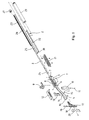
- FIG. 1 in an exploded view schematically compressed air rifle a buttstock 1, a forearm 2 releasably connected thereto, and a barrel 3, which is guided and supported in the forearm 2.
- the buttstock 1 consists of a Shaped body with a rear, bent down end part 4 and a front Receiving part 5, in which a trigger and trigger mechanism with a trigger lever 6 and a shot valve 7 is integrated.
- a trigger and trigger mechanism with a trigger lever 6 and a shot valve 7 is integrated.
- the front receiving part 5 of the rear shaft 1 are In addition, the not shown in detail charging and system parts and the like. Housed.
- the trigger parts, charging parts, the firing valve and the rear end of the barrel are directly in the or mounted on the buttstock 1.
- the shot pressure chamber or Schlag Sharing Service incorporated directly as a hole in the buttstock 1.
- the Deduction mechanism directly integrated in the buttstock 1. It is thus not a separate one Trigger housing required.
- the adjustment for the trigger are immediate mounted in the buttstock 1.
- the Butt stock 1 On the upper side of the front receiving part 5, the Butt stock 1 also designed as a dovetail guide integrated guide 8 for mounting a diopter 9, a riflescope or similar aiming device on.
- a handle 10 is behind the trigger 6 a cylinder screw 11 fastened.
- a jaw plate 12 may be connected via a carrier 13 in a recess 14 inserted at the top of the rear end portion 4 on the buttstock 1 and be fixed by a lateral screw 15.
- a recess 16 at the back of the Backshaft 1 is also a butt plate 17 can be used.
- a hand rest 21 is further fastened.
- Butt stock 1 is made as a molded part from one piece and can e.g. as aluminum casting or the like.
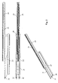
- the forearm 2 shown separately in Figures 2 and 3 consists of a Profile body 22 with an integrated barrel jacket 23 in which the barrel 3 out and about Support rings 24 and 25 is supported.
- the running jacket 23 extends beyond the front End of the barrel 3, so that this is taken up to the front within the barrel jacket 23 is.
- the profile body 22 also includes on the top of the barrel jacket 23 a integrated Komuza 26 on which a comtunnel 27 or a corresponding Target device is mountable.
- the Komique 26 is in the illustrated embodiment also designed as a dovetail guide.
- the profile body 22 includes one of Front accessible receiving opening 28 into which a cylindrical shown in Figure 1 Pressure vessel 29 can be used.
- the forearm 2 At the bottom of the profile body 22 is also a T-shaped guide groove 30 for attachment of the hand rest 21 of a hand stop or Like. Integrated. At its rear end, the forearm 2 has a recess 31 for the front receiving part 8 of the rear shaft 1. At the rear end of the fore-end 2 can also lateral holes 32 for mounting screws for the connection of Rear stock 1 and forearm 2 may be provided.
- Running jacket 23 has a through opening 33 with a circular cross-section, in which the in Figure 1 shown housed 3 and supported on the support rings 24 and 25.
- Profile body 22 is also designed as Schwabenschwanz Entry and on the top the running jacket 23 extending Kommé 26 integrated.
- Die Receiving opening 28 Located below the opening 33 within the profile body 22, the receiving opening 28 for the pressure vessel 29. Die Receiving opening 28 has a substantially circular cross-section. Below the receiving opening 28 is in the profile body 22 also the T-shaped Guide groove 30 integrated.
- the profile body 22 is suitably made of light metal, preferably an aluminum alloy.
- the invention is not limited to the one described above and shown in the drawing Embodiment limited. So it can be e.g. instead of the compressed air or Gas pressure guns also act around an explosive gun.
Landscapes
- Engineering & Computer Science (AREA)
- General Engineering & Computer Science (AREA)
- Toys (AREA)
- Telescopes (AREA)
- Orthopedics, Nursing, And Contraception (AREA)
- Joining Of Building Structures In Genera (AREA)
Abstract
Description
- Figur 1
- ein Sportgewehr in einer Explosionsansicht;
- Figur 2
- einen Vorderschaft des in Figur 1 dargestellten Sportgewehrs in einer Seitenansicht, Draufsicht und einer Perspektive und
- Figur 3
- den in Figur 3 gezeigten Vorderschaft in einer vergrößerten Frontansicht.
Claims (12)
- Gewehr, insbesondere Sportgewehr, mit einem Schaft (1, 2), einem Lauf (3) und einem Abzugs- und Auslösemechanismus (6, 7), dadurch gekennzeichnet, dass der Schaft (1, 2) einen Hinterschaft (1) und einem mit diesem lösbar verbundenen Vorderschaft (2) umfaßt, wobei der Vorderschaft (2) aus einem einteiligen Profilkörper (22) mit integriertem Laufmantel (23) besteht.
- Gewehr nach Anspruch 1, dadurch gekennzeichnet, dass der Profilkörper (22) einen integrierten Kornträger (26) enthält.
- Gewehr nach Anspruch 1 oder 2, dadurch gekennzeichnet, dass der Profilkörper (22) eine integrierte Führungsnut (30) enthält.
- Gewehr nach einem der Ansprüche 1 bis 3, dadurch gekennzeichnet, dass sich der Laufmantel (23) über das vordere Ende des Laufs (3) erstreckt und diesen vollständig umgibt.
- Gewehr nach einem der Ansprüche 1 bis 4, dadurch gekennzeichnet, dass der Laufmantel (23) eine durchgehende Öffnung (33) mit kreisrundem Querschnitt aufweist, in welcher der Lauf (3) über Stützringe (24, 25) abgestützt ist.
- Gewehr nach einem der Ansprüche 1 bis 5, dadurch gekennzeichnet, dass der Profilkörper (22) eine integrierte Aufnahmeöffnung (28) für einen Druckbehälter (29) aufweist.
- Gewehr nach einem der Ansprüche 1 bis 6, dadurch gekennzeichnet, dass der Vorderschaft (2) an seinem hinteren Ende eine Aussparung (31) für ein vorderes Aufnahmeteil (8) des Hinterschafts (1) enthält.
- Gewehr nach einem der Ansprüche 1 bis 7, dadurch gekennzeichnet, dass der Hinterschaft (1) aus einem Stück mit einer integrierten Führung (8) zur Befestigung eines Diopters (9) oder einer anderen geeigneten Zielfernrichtung besteht.
- Gewehr nach einem der Ansprüche 1 bis 8, dadurch gekennzeichnet, dass in den Hinterschaft (1) der Abzugs- und Auslösemechanismus (6, 7) integriert ist.
- Gewehr nach einem der Ansprüche 1 bis 9, dadurch gekennzeichnet, dass an dem Hinterschaft (1) ein Griffstück (10) befestigbar ist.
- Gewehr nach einem der Ansprüche 1 bis 10, dadurch gekennzeichnet, dass an dem Hinterschaft (1) eine Schaftkappenplatte (17) mit einer Schaftkappe (20) montierbar ist.
- Gewehr nach einem der Ansprüche 1 bis 11, dadurch gekennzeichnet, dass an dem Hinterschaft (1) eine Backenplatte (12) befestigbar ist.
Applications Claiming Priority (2)
| Application Number | Priority Date | Filing Date | Title |
|---|---|---|---|
| DE20315989U DE20315989U1 (de) | 2003-10-17 | 2003-10-17 | Gewehr |
| DE20315989U | 2003-10-17 |
Publications (2)
| Publication Number | Publication Date |
|---|---|
| EP1524485A1 true EP1524485A1 (de) | 2005-04-20 |
| EP1524485B1 EP1524485B1 (de) | 2008-06-25 |
Family
ID=34223613
Family Applications (1)
| Application Number | Title | Priority Date | Filing Date |
|---|---|---|---|
| EP04022908A Expired - Lifetime EP1524485B1 (de) | 2003-10-17 | 2004-09-25 | Gewehr mit einem am Vorderschaft integrierten Laufmantel |
Country Status (4)
| Country | Link |
|---|---|
| US (1) | US20050183316A1 (de) |
| EP (1) | EP1524485B1 (de) |
| AT (1) | ATE399299T1 (de) |
| DE (2) | DE20315989U1 (de) |
Families Citing this family (1)
| Publication number | Priority date | Publication date | Assignee | Title |
|---|---|---|---|---|
| DE102017130382A1 (de) * | 2017-12-18 | 2019-07-18 | German Sport Guns Gmbh | Luftgewehr |
Citations (4)
| Publication number | Priority date | Publication date | Assignee | Title |
|---|---|---|---|---|
| US1428081A (en) * | 1921-04-19 | 1922-09-05 | Fuchs Johann | Rifle |
| GB836697A (en) * | 1955-06-25 | 1960-06-09 | Francis Henry Woodcock | Improvements in or relating to small arms |
| US4388773A (en) * | 1980-03-07 | 1983-06-21 | Fabrica D'armi Pietro Beretta S.P.A. | Lever-type closing device for blocking and unblocking the barrel of automatic, portable firearms |
| US20030150151A1 (en) * | 2002-02-09 | 2003-08-14 | Manfred Orth | Rifle comprising a stock, a forearm and a barrel |
Family Cites Families (18)
| Publication number | Priority date | Publication date | Assignee | Title |
|---|---|---|---|---|
| US160935A (en) * | 1875-03-16 | Improvement in stocks for fire-arms | ||
| US988202A (en) * | 1910-10-19 | 1911-03-28 | Paul Mauser | Firearm. |
| US1206234A (en) * | 1915-08-20 | 1916-11-28 | Albert K Lovell | Metal stock and receiver for firearms. |
| BE387572A (de) * | 1931-04-07 | |||
| US2436175A (en) * | 1942-05-23 | 1948-02-17 | Ernest C Neal | Automatic firearm |
| US2483752A (en) * | 1945-11-10 | 1949-10-04 | Associated Dev And Res Corp | Combined magazine receiver and barrel for toy guns |
| US2674822A (en) * | 1951-05-03 | 1954-04-13 | Rene R Studler | Forearm and handguard protector |
| BE559092A (de) * | 1957-05-20 | |||
| FR1197324A (fr) * | 1958-06-19 | 1959-11-30 | Manufrance | Guides-protecteurs pour fusils de chasse semi-automatiques |
| US3023527A (en) * | 1958-12-15 | 1962-03-06 | Remington Arms Co Inc | Firearm having receiver bearing surfaces of synthetic resinous material |
| DE1428627C2 (de) * | 1963-12-12 | 1974-08-01 | Fa. Carl Walther, 7900 Ulm | Druckluftschußwaffe |
| US3939589A (en) * | 1973-01-19 | 1976-02-24 | Tellie Paul E | Firearms with forestock |
| DE2445909A1 (de) * | 1974-09-26 | 1976-04-15 | Schirnecker Hans Ludwig | Feuerwaffe |
| DE8803831U1 (de) * | 1988-03-22 | 1988-05-05 | UMAREX Sportwaffen GmbH & Co KG, 5760 Arnsberg | Druckluftschußwaffe |
| FR2664969B1 (fr) * | 1990-07-20 | 1994-05-06 | Industrias El Gamo Sa | Perfectionnements apportes aux procedes de fabrication de carabines d'air comprime, a canon basculant, et carabine obtenue par leur mise en óoeuvre. |
| US5048215A (en) * | 1990-08-30 | 1991-09-17 | Calico Light Weapon Systems | Front grip for a firearm |
| US6301817B1 (en) * | 1996-11-14 | 2001-10-16 | Aaron G. Hogue | Long gun stock |
| US20040226211A1 (en) * | 2003-05-16 | 2004-11-18 | Ra Brands. L.L.C. | Composite receiver for firearms |
-
2003
- 2003-10-17 DE DE20315989U patent/DE20315989U1/de not_active Expired - Lifetime
-
2004
- 2004-09-25 EP EP04022908A patent/EP1524485B1/de not_active Expired - Lifetime
- 2004-09-25 AT AT04022908T patent/ATE399299T1/de active
- 2004-09-25 DE DE502004007432T patent/DE502004007432D1/de not_active Expired - Lifetime
- 2004-10-12 US US10/963,425 patent/US20050183316A1/en not_active Abandoned
Patent Citations (4)
| Publication number | Priority date | Publication date | Assignee | Title |
|---|---|---|---|---|
| US1428081A (en) * | 1921-04-19 | 1922-09-05 | Fuchs Johann | Rifle |
| GB836697A (en) * | 1955-06-25 | 1960-06-09 | Francis Henry Woodcock | Improvements in or relating to small arms |
| US4388773A (en) * | 1980-03-07 | 1983-06-21 | Fabrica D'armi Pietro Beretta S.P.A. | Lever-type closing device for blocking and unblocking the barrel of automatic, portable firearms |
| US20030150151A1 (en) * | 2002-02-09 | 2003-08-14 | Manfred Orth | Rifle comprising a stock, a forearm and a barrel |
Also Published As
| Publication number | Publication date |
|---|---|
| EP1524485B1 (de) | 2008-06-25 |
| DE20315989U1 (de) | 2005-02-24 |
| US20050183316A1 (en) | 2005-08-25 |
| ATE399299T1 (de) | 2008-07-15 |
| DE502004007432D1 (de) | 2008-08-07 |
Similar Documents
| Publication | Publication Date | Title |
|---|---|---|
| EP3368853B1 (de) | Adapter zur anbringung wenigstens einer zusatzeinrichtung an einer selbstlade-feuerwaffe und mit diesem ausgestattete selbstlade-feuerwaffe | |
| DE102018132756B4 (de) | Umrüstsatz für eine Kurzwaffe | |
| EP4015978B1 (de) | Hinterschaft einer handfeuerwaffe und handfeuerwaffe mit einem derartigen hinterschaft | |
| DE102008007341A1 (de) | Zusatzgriff für eine Handfeuerwaffe | |
| EP0460362A2 (de) | Laufwechselsystem für eine rückstossarme Feuerwaffe,insbesondere für Pistolen,Maschinenpistolen | |
| DE202012011647U1 (de) | Komponententräger für eine Feuerwaffe | |
| EP1303735B1 (de) | Waffensystem | |
| WO2004085950A2 (de) | Adapter | |
| EP1924815B1 (de) | Gaszylinderbauteil und handfeuerwaffe | |
| DE2349339B2 (de) | Gasdruckladeeinrichtung für eine Selbstladewaffe | |
| DE10126761B4 (de) | Kurzrepetiergewehr | |
| DE102018132757A1 (de) | Umrüstsatz für eine Kurzwaffe | |
| EP3973244B1 (de) | Obergehäuse für eine feuerwaffe | |
| DE29923688U1 (de) | Gewehr | |
| EP1524485B1 (de) | Gewehr mit einem am Vorderschaft integrierten Laufmantel | |
| AT516501B1 (de) | Feuerwaffe vom Drehkopfverschluss-Typ | |
| DE10002587C2 (de) | Tiefliegende Halterungsvorrichtung zur Befestigung eines Zielfernrohres auf Jagd- und Sportwaffen | |
| EP1471325B1 (de) | Vorderschaft aus Kunststoff | |
| DE3522155C2 (de) | Faustfeuerwaffe | |
| DE4317310A1 (de) | Schußwaffe | |
| EP1388723B1 (de) | Langwaffe zu Wettkampfzwecken | |
| DE2816128A1 (de) | Mehrlaeufiges gewehr | |
| EP1703246B1 (de) | Mehrläufige Handfeuerwaffe | |
| DE102016102403A1 (de) | Kipplaufwaffe | |
| DE202016100700U1 (de) | Kipplaufwaffe |
Legal Events
| Date | Code | Title | Description |
|---|---|---|---|
| PUAI | Public reference made under article 153(3) epc to a published international application that has entered the european phase |
Free format text: ORIGINAL CODE: 0009012 |
|
| AK | Designated contracting states |
Kind code of ref document: A1 Designated state(s): AT BE BG CH CY CZ DE DK EE ES FI FR GB GR HU IE IT LI LU MC NL PL PT RO SE SI SK TR |
|
| AX | Request for extension of the european patent |
Extension state: AL HR LT LV MK |
|
| 17P | Request for examination filed |
Effective date: 20051020 |
|
| AKX | Designation fees paid |
Designated state(s): AT BE BG CH CY CZ DE DK EE ES FI FR GB GR HU IE IT LI LU MC NL PL PT RO SE SI SK TR |
|
| GRAP | Despatch of communication of intention to grant a patent |
Free format text: ORIGINAL CODE: EPIDOSNIGR1 |
|
| GRAS | Grant fee paid |
Free format text: ORIGINAL CODE: EPIDOSNIGR3 |
|
| GRAA | (expected) grant |
Free format text: ORIGINAL CODE: 0009210 |
|
| AK | Designated contracting states |
Kind code of ref document: B1 Designated state(s): AT BE BG CH CY CZ DE DK EE ES FI FR GB GR HU IE IT LI LU MC NL PL PT RO SE SI SK TR |
|
| REG | Reference to a national code |
Ref country code: GB Ref legal event code: FG4D Free format text: NOT ENGLISH |
|
| REG | Reference to a national code |
Ref country code: CH Ref legal event code: NV Representative=s name: LUCHS & PARTNER PATENTANWAELTE Ref country code: CH Ref legal event code: EP |
|
| REF | Corresponds to: |
Ref document number: 502004007432 Country of ref document: DE Date of ref document: 20080807 Kind code of ref document: P |
|
| REG | Reference to a national code |
Ref country code: IE Ref legal event code: FG4D Free format text: LANGUAGE OF EP DOCUMENT: GERMAN |
|
| PG25 | Lapsed in a contracting state [announced via postgrant information from national office to epo] |
Ref country code: SI Free format text: LAPSE BECAUSE OF FAILURE TO SUBMIT A TRANSLATION OF THE DESCRIPTION OR TO PAY THE FEE WITHIN THE PRESCRIBED TIME-LIMIT Effective date: 20080625 Ref country code: FI Free format text: LAPSE BECAUSE OF FAILURE TO SUBMIT A TRANSLATION OF THE DESCRIPTION OR TO PAY THE FEE WITHIN THE PRESCRIBED TIME-LIMIT Effective date: 20080625 |
|
| PG25 | Lapsed in a contracting state [announced via postgrant information from national office to epo] |
Ref country code: NL Free format text: LAPSE BECAUSE OF FAILURE TO SUBMIT A TRANSLATION OF THE DESCRIPTION OR TO PAY THE FEE WITHIN THE PRESCRIBED TIME-LIMIT Effective date: 20080625 Ref country code: PL Free format text: LAPSE BECAUSE OF FAILURE TO SUBMIT A TRANSLATION OF THE DESCRIPTION OR TO PAY THE FEE WITHIN THE PRESCRIBED TIME-LIMIT Effective date: 20080625 |
|
| NLV1 | Nl: lapsed or annulled due to failure to fulfill the requirements of art. 29p and 29m of the patents act | ||
| PG25 | Lapsed in a contracting state [announced via postgrant information from national office to epo] |
Ref country code: SE Free format text: LAPSE BECAUSE OF FAILURE TO SUBMIT A TRANSLATION OF THE DESCRIPTION OR TO PAY THE FEE WITHIN THE PRESCRIBED TIME-LIMIT Effective date: 20080925 Ref country code: PT Free format text: LAPSE BECAUSE OF FAILURE TO SUBMIT A TRANSLATION OF THE DESCRIPTION OR TO PAY THE FEE WITHIN THE PRESCRIBED TIME-LIMIT Effective date: 20081125 Ref country code: CZ Free format text: LAPSE BECAUSE OF FAILURE TO SUBMIT A TRANSLATION OF THE DESCRIPTION OR TO PAY THE FEE WITHIN THE PRESCRIBED TIME-LIMIT Effective date: 20080625 Ref country code: ES Free format text: LAPSE BECAUSE OF FAILURE TO SUBMIT A TRANSLATION OF THE DESCRIPTION OR TO PAY THE FEE WITHIN THE PRESCRIBED TIME-LIMIT Effective date: 20081006 |
|
| REG | Reference to a national code |
Ref country code: IE Ref legal event code: FD4D |
|
| PG25 | Lapsed in a contracting state [announced via postgrant information from national office to epo] |
Ref country code: RO Free format text: LAPSE BECAUSE OF FAILURE TO SUBMIT A TRANSLATION OF THE DESCRIPTION OR TO PAY THE FEE WITHIN THE PRESCRIBED TIME-LIMIT Effective date: 20080625 Ref country code: SK Free format text: LAPSE BECAUSE OF FAILURE TO SUBMIT A TRANSLATION OF THE DESCRIPTION OR TO PAY THE FEE WITHIN THE PRESCRIBED TIME-LIMIT Effective date: 20080625 |
|
| BERE | Be: lapsed |
Owner name: S.A.T. SWISS ARMS TECHNOLOGY A.G. Effective date: 20080930 |
|
| PG25 | Lapsed in a contracting state [announced via postgrant information from national office to epo] |
Ref country code: BG Free format text: LAPSE BECAUSE OF FAILURE TO SUBMIT A TRANSLATION OF THE DESCRIPTION OR TO PAY THE FEE WITHIN THE PRESCRIBED TIME-LIMIT Effective date: 20080925 Ref country code: IE Free format text: LAPSE BECAUSE OF FAILURE TO SUBMIT A TRANSLATION OF THE DESCRIPTION OR TO PAY THE FEE WITHIN THE PRESCRIBED TIME-LIMIT Effective date: 20080625 Ref country code: DK Free format text: LAPSE BECAUSE OF FAILURE TO SUBMIT A TRANSLATION OF THE DESCRIPTION OR TO PAY THE FEE WITHIN THE PRESCRIBED TIME-LIMIT Effective date: 20080625 Ref country code: MC Free format text: LAPSE BECAUSE OF NON-PAYMENT OF DUE FEES Effective date: 20080930 Ref country code: EE Free format text: LAPSE BECAUSE OF FAILURE TO SUBMIT A TRANSLATION OF THE DESCRIPTION OR TO PAY THE FEE WITHIN THE PRESCRIBED TIME-LIMIT Effective date: 20080625 |
|
| PLBE | No opposition filed within time limit |
Free format text: ORIGINAL CODE: 0009261 |
|
| STAA | Information on the status of an ep patent application or granted ep patent |
Free format text: STATUS: NO OPPOSITION FILED WITHIN TIME LIMIT |
|
| GBPC | Gb: european patent ceased through non-payment of renewal fee |
Effective date: 20080925 |
|
| 26N | No opposition filed |
Effective date: 20090326 |
|
| REG | Reference to a national code |
Ref country code: FR Ref legal event code: ST Effective date: 20090529 |
|
| PG25 | Lapsed in a contracting state [announced via postgrant information from national office to epo] |
Ref country code: BE Free format text: LAPSE BECAUSE OF NON-PAYMENT OF DUE FEES Effective date: 20080930 |
|
| PG25 | Lapsed in a contracting state [announced via postgrant information from national office to epo] |
Ref country code: IT Free format text: LAPSE BECAUSE OF FAILURE TO SUBMIT A TRANSLATION OF THE DESCRIPTION OR TO PAY THE FEE WITHIN THE PRESCRIBED TIME-LIMIT Effective date: 20080625 |
|
| PG25 | Lapsed in a contracting state [announced via postgrant information from national office to epo] |
Ref country code: FR Free format text: LAPSE BECAUSE OF NON-PAYMENT OF DUE FEES Effective date: 20080930 |
|
| PG25 | Lapsed in a contracting state [announced via postgrant information from national office to epo] |
Ref country code: GB Free format text: LAPSE BECAUSE OF NON-PAYMENT OF DUE FEES Effective date: 20080925 |
|
| PG25 | Lapsed in a contracting state [announced via postgrant information from national office to epo] |
Ref country code: LU Free format text: LAPSE BECAUSE OF NON-PAYMENT OF DUE FEES Effective date: 20080925 Ref country code: HU Free format text: LAPSE BECAUSE OF FAILURE TO SUBMIT A TRANSLATION OF THE DESCRIPTION OR TO PAY THE FEE WITHIN THE PRESCRIBED TIME-LIMIT Effective date: 20081226 Ref country code: CY Free format text: LAPSE BECAUSE OF FAILURE TO SUBMIT A TRANSLATION OF THE DESCRIPTION OR TO PAY THE FEE WITHIN THE PRESCRIBED TIME-LIMIT Effective date: 20080625 |
|
| PG25 | Lapsed in a contracting state [announced via postgrant information from national office to epo] |
Ref country code: TR Free format text: LAPSE BECAUSE OF FAILURE TO SUBMIT A TRANSLATION OF THE DESCRIPTION OR TO PAY THE FEE WITHIN THE PRESCRIBED TIME-LIMIT Effective date: 20080625 |
|
| PG25 | Lapsed in a contracting state [announced via postgrant information from national office to epo] |
Ref country code: GR Free format text: LAPSE BECAUSE OF FAILURE TO SUBMIT A TRANSLATION OF THE DESCRIPTION OR TO PAY THE FEE WITHIN THE PRESCRIBED TIME-LIMIT Effective date: 20080926 |
|
| PGFP | Annual fee paid to national office [announced via postgrant information from national office to epo] |
Ref country code: AT Payment date: 20100924 Year of fee payment: 7 |
|
| PGFP | Annual fee paid to national office [announced via postgrant information from national office to epo] |
Ref country code: CH Payment date: 20100930 Year of fee payment: 7 Ref country code: DE Payment date: 20101104 Year of fee payment: 7 |
|
| REG | Reference to a national code |
Ref country code: CH Ref legal event code: PL |
|
| REG | Reference to a national code |
Ref country code: DE Ref legal event code: R119 Ref document number: 502004007432 Country of ref document: DE Effective date: 20120403 |
|
| PG25 | Lapsed in a contracting state [announced via postgrant information from national office to epo] |
Ref country code: CH Free format text: LAPSE BECAUSE OF NON-PAYMENT OF DUE FEES Effective date: 20110930 Ref country code: LI Free format text: LAPSE BECAUSE OF NON-PAYMENT OF DUE FEES Effective date: 20110930 Ref country code: DE Free format text: LAPSE BECAUSE OF NON-PAYMENT OF DUE FEES Effective date: 20120403 |
|
| REG | Reference to a national code |
Ref country code: AT Ref legal event code: MM01 Ref document number: 399299 Country of ref document: AT Kind code of ref document: T Effective date: 20110925 |
|
| PG25 | Lapsed in a contracting state [announced via postgrant information from national office to epo] |
Ref country code: AT Free format text: LAPSE BECAUSE OF NON-PAYMENT OF DUE FEES Effective date: 20110925 |