EP1523919A1 - Support et article nettoyant utilisant ledit support - Google Patents
Support et article nettoyant utilisant ledit support Download PDFInfo
- Publication number
- EP1523919A1 EP1523919A1 EP03741481A EP03741481A EP1523919A1 EP 1523919 A1 EP1523919 A1 EP 1523919A1 EP 03741481 A EP03741481 A EP 03741481A EP 03741481 A EP03741481 A EP 03741481A EP 1523919 A1 EP1523919 A1 EP 1523919A1
- Authority
- EP
- European Patent Office
- Prior art keywords
- handle
- support member
- cleaning
- locking member
- locking
- Prior art date
- Legal status (The legal status is an assumption and is not a legal conclusion. Google has not performed a legal analysis and makes no representation as to the accuracy of the status listed.)
- Granted
Links
Images


Classifications
-
- A—HUMAN NECESSITIES
- A47—FURNITURE; DOMESTIC ARTICLES OR APPLIANCES; COFFEE MILLS; SPICE MILLS; SUCTION CLEANERS IN GENERAL
- A47L—DOMESTIC WASHING OR CLEANING; SUCTION CLEANERS IN GENERAL
- A47L13/00—Implements for cleaning floors, carpets, furniture, walls, or wall coverings
- A47L13/10—Scrubbing; Scouring; Cleaning; Polishing
- A47L13/38—Other dusting implements
-
- A—HUMAN NECESSITIES
- A47—FURNITURE; DOMESTIC ARTICLES OR APPLIANCES; COFFEE MILLS; SPICE MILLS; SUCTION CLEANERS IN GENERAL
- A47L—DOMESTIC WASHING OR CLEANING; SUCTION CLEANERS IN GENERAL
- A47L13/00—Implements for cleaning floors, carpets, furniture, walls, or wall coverings
- A47L13/10—Scrubbing; Scouring; Cleaning; Polishing
- A47L13/20—Mops
- A47L13/24—Frames for mops; Mop heads
- A47L13/254—Plate frames
- A47L13/256—Plate frames for mops made of cloth
-
- B—PERFORMING OPERATIONS; TRANSPORTING
- B25—HAND TOOLS; PORTABLE POWER-DRIVEN TOOLS; MANIPULATORS
- B25G—HANDLES FOR HAND IMPLEMENTS
- B25G1/00—Handle constructions
- B25G1/06—Handle constructions reversible or adjustable for position
Definitions
- the present invention relates to a device for holding a disposable or reusable cleaning wiper and a cleaning tool constructed of the holding device and the cleaning wiper.
- Japanese Unexamined Patent Publication Nos. 9-154791 and 9-38009 disclose cleaning tools for holding a cleaning cloth comprising nonwoven fabric and the like, in which a head for supporting the cleaning cloth is provided at a front end of a short handle or axially extendable handle that can be held with one hand.
- the head disclosed in the above-mentioned Patent Publications is fixed in position so as not to move at the front end of the handle, the handle held with hand for cleaning a surface to be cleaned with the cleaning cloth attached to the head need be turned in various directions in accordance with the shape of the surface to be cleaned. Therefore, it is not suitable for cleaning a variously oriented surface to be cleaned such as furniture surface.
- Japanese Unexamined Patent Publication Nos. 51-85273 and 2002-17640 disclose cleaning tools in which a brush-like cleaning device is attached to a front end of a handle so as to be adjustable in position.
- the brush-like cleaning device used for these cleaning tools is pivotally attached to the front end of the handle.
- a plurality of recesses are formed in an outer periphery of a rotary portion that rotates together with the cleaning device, while a locking member for fitting in the recesses are provided in the handle, so that the position of the brush-like cleaning device can be changed and fixed by fitting the locking member in the recesses.
- the locking member cannot enter the recess if the rotary ring is turned or the operating part is pushed forward by hand before the locking member is exactly confronted by the recess, so that the locking member sometimes fails in fitting into the recess. Accordingly, the operation of the rotary ring or the operating part must be done after the locking member is confronted by the recess, so that it tends to take much time to certainly fix the cleaning device in position.
- the cleaning devices disclosed in the two Patent Publications still moreover, although the position of the brush-like cleaning device can be changed within a predetermined angular range, the cleaning device cannot be folded back to overlie the handle. That is, the cleaning tools disclosed in the two Patent Publications are not intended to support a disposable cleaning wiper, but the brush-like cleaning device for a long time use is attached to the handle. Therefore, the holding device is intended to be left attached even when it is not used, not assuming such a usage that the cleaning tool is folded back for storage with a wiper removed therefrom, unlike a cleaning tool to which a disposable wiper is intended to be attached.
- the present invention has been worked out in view of the shortcomings in the prior art set forth above. It is therefore an object of the present invention to provide a holding device, wherein the position of a support member to which a cleaning wiper is to be attached can be changed with a simple operation and the support member can be stabilized in predetermined positions without causing unexpected turn, and a cleaning tool with the holding device.
- a holding device for a cleaning wiper comprising:
- the locking member can be released from the recesses by moving the locking member away from the recesses against the biasing force of the biasing member, thereby permitting the support member to turn. Thereafter, when the operating force to the locking member is eliminated, the locking member moves along the axis of the handle due to the biasing force, whereby the locking member fits in one recess so that the support member goes to an engaged and fixed state (locked state).
- the locking member can automatically fit in the recess due to the biasing force so that the support member goes to the engaged and fixed state. That is, when the position of the support member is to be changed, the support member can automatically go to the engaged and fixed state such that the locking member is moved away from the recess by operation of the operating member, the operating member is let go of during a turn of the support member, and then the support member is turned only a little more.
- the operation for changing the position of the support member is quite simple.
- the locking member since the locking member is so provided axially movably inside the handle as to fit in the recess of the support member, the locking member can be made thick as well as the support member can be made wide at its portion having the recesses. Accordingly, the locking strength when the locking member fits in the recess can be increased.
- the handle can be made thin when the locking member is provided axially movably.
- the pivot connection between the handle and the support member can be of a simple construction and the radius from the pivot axis to the sliding surfaces can be made large to increase the fixing strength when the locking member is engaged with and fixed to the recess. Accordingly, when the support member goes to the engaged and fixed state, the position of the support member can be stabilized so as not to cause unexpected change.
- the present invention may be constructed such that the sliding surfaces are formed on an imaginary cylindrical surface with center at the pivot axis.
- the sliding surfaces are part of the cylindrical surface, when the support member is turned with the locking member in contact with the sliding surface, the locking member can smoothly slide on the sliding surface to fit into the recess.
- the sliding surfaces located between adjacent recesses may be flat surfaces extending in a direction tangential to an imaginary circle with center at the pivot axis.
- the present invention may be constructed such that the support member has a cleaning support surface for pressing a cleaning wiper attached thereto against a surface to be cleaned, wherein selective engagement of the locking member in the recesses permits a stepwise change of angle between the shaft axis and the cleaning support surface.
- the handle With the stepwise change of the angle of the cleaning support surface for pressing the cleaning wiper against a surface to be cleaned, the handle can be held with hand always in suitable positions for cleaning operation, so that an object such as furniture having variously oriented surfaces to be cleaned, ceiling, and the like can be easily cleaned.
- one of the recesses is a fold locking recess and when the locking member engages in the fold locking recess, the support member is folded back to substantially overlie the handle.
- the support member when the holding device is not used, the support member can be folded back to substantially overlie the handle with the cleaning wiper removed from the support member, for instance, so that a large storage space is not required.
- the present invention may be constructed such that the operating member is a push button that is externally exposed on an outer periphery of the handle and movable in a direction crossing the shaft axis, and at least one of the push button and the locking member has an inclined sliding surface inclined to both a direction along which the push button is to be pushed and a direction along which the locking member is movable, wherein a sliding component force acting on the inclined sliding surface as the push button is pushed permits the locking member to move against the biasing force of the biasing member.
- the handle can be made thin, as set forth above.
- the push button is provided to be movable in a direction crossing the shaft axis of the handle, the operation for releasing the engagement and fixation (lock) between the locking member and the recess can be performed quite easily.
- the present invention may be constructed such that the operating member is a sliding button that is externally exposed on an outer periphery of the handle and movable along the shaft axis, wherein the sliding button permits the locking member to move against the biasing force of the biasing member.
- the sliding button is thus provided to be movable axially of the handle, the inner structure of the handle can be made simple, and even if the handle is made thin, the locking member can be certainly operated.
- a cleaning tool comprising: the foregoing holding device; and a cleaning wiper to be attached to the support member, wherein the cleaning wiper is a disposable wiper comprising nonwoven fabric, paper or a combination of nonwoven fabric and a bundle of fibers, and the cleaning wiper is supported by the support member with the support member inserted into holding spaces formed in the cleaning wiper.
- the cleaning wiper can be made soft, it can easily be attached to the support member or replaced.
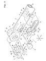
- Figs. 1A, 1B and 1C are general side views showing a holding device according to a first embodiment of the present invention, wherein Fig. 1A shows a state where a cleaning support surface of a support member is oriented parallel with a shaft axis of a handle, Fig. 1B shows a state where the cleaning support surface is oriented perpendicular to the shaft axis of the handle, and Fig. 1C shows a state where the support member is folded back to substantially overlie the handle.
- Fig. 2 is a perspective view showing a structure of the support member and a cleaning wiper to be attached to the support member;
- Fig. 3 is an exploded perspective view showing a pivot connection between the handle and the support member and a locking mechanism;
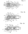
- Fig. 4 is a sectional view taken along an XY-plane, showing the pivot connection and the locking mechanism;
- Figs 5A and 5B and Figs. 6A and 6B are sectional views taken along a YZ-plane, showing the support member in different positions.
- a holding device 1 has a handle 2 and a housing handle 3.
- the handle 2 is illustrated as projecting forwardly from the housing handle 3, but the handle 2 can be retracted into the housing handle 3 so as to decrease the length of the assembly of the handle 2 and the housing handle 3.
- the housing handle 3 may be a telescopic handle so as to increase the length of the assembly of the handle 2 and the housing handle 3.
- the handle 2 is a cylinder of a hollow circular cross-section.
- the housing handle 3 is also a cylinder of a hollow circular cross-section. Referring to Fig. 1A, the shaft axis of the handle 2 and the housing handle 3 is indicated by Os.
- a support member 4 is pivotally connected to the front end of the handle 2 through a pivot connection 5.
- the pivot axis of the support member 4 at the pivot connection 5 is indicated by Or.
- the pivot axis Or is oriented in a direction perpendicularly intersecting the shaft axis Os of the handle 2.
- the support member 4 is pivotable about the pivot axis Or, and after the support member 4 is turned to respective positions, the support member 4 can be engaged and fixed (locked) by a locking mechanism 6 provided inside the handle 2.
- the lower surface of the support member 4 is a cleaning support surface 4a for pressing a cleaning wiper 8 attached to the support member 4 against a surface to be cleaned.
- the support member 4 can be engaged and fixed at five different positions.
- Fig. 1A shows a first cleaning position (i), in which the cleaning support surface 4a of the support member 4 is substantially parallel with the shaft axis Os of the handle 2, a second cleaning position (ii), in which the cleaning support surface 4a is turned by ⁇ 1 downwardly from the first cleaning position (i), and a third cleaning position (iii), in which the cleaning support surface 4a is turned by ⁇ 1 upwardly from the first cleaning position (i).
- Fig. 1B shows a fourth cleaning position (iv), in which the cleaning support surface 4a is further turned by ⁇ 1 upwardly from the third cleaning position (iii), and at this time, the cleaning support surface 4a becomes substantially perpendicular to the shaft axis Os.
- the support member 4 is further turned clockwise by ⁇ 2 from the fourth cleaning position (iv) of Fig. 1B, the support member 4 thus folded back overlies the handle 2 to take a folded position (v), wherein the cleaning support surface 4a faces upward and becomes substantially parallel with the shaft axis Os.
- the pivot angles ⁇ 1 of the support member 4 between adjacent cleaning positions are equal, while the pivot angel ⁇ 2 of the support member 4 from the fourth cleaning position (iv) to the folded position (v) is set larger than the pivot angles ⁇ 1 between adjacent cleaning positions. For instance, ⁇ 1 is 45 degrees, and ⁇ 2 is 90 degrees.
- a push button 70 as operating member for releasing the engagement and fixation (lock) through the locking mechanism 6, wherein the push button 70 projects outwardly beyond the outer periphery of the handle 2.
- the push button 70 is so positioned as not to interfere with the operation of the support member 4 in the folded position (v).
- Individual components constituting the handle 2, the housing handle 3, the support member 4, the pivot connection 5 and the locking mechanism 6 are all made of synthetic resin, such as ABS, vinyl chloride, PE (polyethylene), PP (polypropylene) and PET (polyethylene terephthalate), except for coil spring.
- synthetic resin such as ABS, vinyl chloride, PE (polyethylene), PP (polypropylene) and PET (polyethylene terephthalate), except for coil spring.
- the support body 4 has an arm 14 extending forwardly from the pivot connection 5, and the arm 14 is bifurcated to provide support strips 11, 11 in the form of parallel flat plates.
- the arm 14 is bifurcated to provide support strips 11, 11 in the form of parallel flat plates.
- two thin deformable projections 12, 12 are integrally formed.
- a clip 13 is integrally formed to extend forwardly between the support strips 11, 11.
- the lower surfaces of the support strips 11, 11 are regarded as the cleaning support surface 4a.
- the cleaning wiper 8 of Fig. 2 is a disposable, soft wiper, of which a main body 21 comprises a nonwoven fabric, a stack of nonwoven fabrics, a stack of papers, a foamed resin material, a stack of a nonwoven fabric and a bundle of fibers that is referred to as tow, or the like.
- a holding sheet 22 that comprises a nonwoven fabric or the like.
- the main body 21 and the holding sheet 22 are joined together at a pair of longitudinally extending side bond lines 23, 23 and a center bond line 24 extending parallel with and between the two side bond lines 23, 23.
- holding spaces 25, 25 Between the main body 21 and the holding sheet 22, there are formed holding spaces 25, 25 individually defined between one side bond line 23 and the center bond line 24.
- the individual holding spaces 25 have openings 25a, 25a on longitudinally opposite sides of the main body 21.
- the main body 21 of the cleaning wiper 8 beneath the cleaning support surface 4a i.e., the lower surfaces of the support strips 11, 11
- a surface to be cleaned such as floor and furniture.
- a washable (reusable) cleaning wiper may be attached to the support member 4, in place of the disposable wiper.
- the support member 4 is integrally formed, at its rear end of the arm 14, with a generally disc-shaped rotary portion 31, and a shaft hole 32 is formed to passes through the rotary portion 31 in the X-direction.
- the handle 2 is integrally formed, at its front end, with a pair of disc-shaped support portions 33, 33 to have a support space 34 between the support portions 33, 33. Support holes 35, 35 are formed to pass through the support portions 33, 33 in the X-direction.
- the thickness of the rotary portion 31 formed in the support member 4 is substantially equal to the width of the support space 34, so that the rotary portion 31 can be inserted into the support space 34 substantially without play.
- a first support shaft 36a is inserted into the support hole 35 from outside one support portion 33, while a second support shaft 36b is inserted into the support hole 35 from outside the other support portion 33.
- the first and second support shafts 36a, 36b are then inserted into the shaft hole 32 of the rotary portion 31 to fit each other within the shaft hole 32, wherein the first and second support shafts 36a, 36b may be bonded and fixed to each other, if desired.
- the shaft axis of the first and second support shafts 36a, 36b is the pivot axis Or.
- the pivot axis Or is oriented in a direction perpendicularly intersecting the shaft axis Os of the handle 2.
- the rotary portion 31, being integral with the support member 4 has first, second third and fourth recesses 38a, 38b, 38c and 38d formed in circumferentially spaced relation toward the pivot axis Or.
- the individual recesses 38a, 38b, 38c and 38d are formed linearly along the X-direction (direction parallel with the pivot axis Or) at a constant width.
- adjacent recesses i.e., the first and second recesses 38a and 38b, the first and third recesses 38a and 38c, and the third and fourth recesses 38c and 38d
- ⁇ 1 is 45 degrees, for instance.
- a fold locking recess 38e is provided at a position spaced counterclockwise apart from the fourth recess 38d by ⁇ 2.
- the ⁇ 2 is 90 degrees, for instance.
- a first sliding surface 39a is provided between the first and second recesses 38a and 38b
- a second sliding surface 39b is provided between the first and third recesses 38a and 38c
- a third sliding surface 39c is provided between the third and fourth recesses 38c and 38d.
- a fold sliding surface 39d is provided between the fourth recesses 38d and the fold locking recess 38e.
- the individual sliding surfaces 39a, 39b, 39c and 39d are formed on an imaginary cylindrical surface with radius R and center at the pivot axis Or.
- the rotary portion 31 of the support member 4 is held between the support portions 33 and 33 provided at the front end of the handle 2, not only the width but also the radius R of the rotary portion 31 can be made relatively large, so that the strength of engagement and fixation (locking strength) at the time when a locking projection 53 (which will be described later in detail) fits in the recess can be increased.
- the handle 2 is a cylinder having a mechanism housing space 2a inside of it.
- a partition 41 is integrally formed to separate the mechanism housing space 2a, at its front side adjacent the support portions 33, from the support space 34, and a rectangular window 42 is formed to pass through the partition 41 axially of the handle 2 (i.e., along the shaft axis Os).
- the handle 2 At a location closely spaced apart from the support portions 33 toward the rear side (toward the housing handle 3), the handle 2 has an operating hole 43 passing through the cylinder wall of the handle 2 in the X-direction. At a location spaced apart from the operating hole 43 toward the rear side, there is also formed a small-diameter fitting hole 44 passing through the cylinder wall in the X-direction.
- a pair of sliding grooves 2b and 2c are formed to extend axially of the handle 2 from the inward surface of the partition 41. The sliding grooves 2b and 2c are located in opposite positions vertically (in the Z-direction).
- the locking member 50 has a sliding body 51, whose upper and lower surfaces 51a and 51b are curved surfaces having the same curvature as the inner periphery of the handle 2 that defines the mechanism housing space 2a, so that when the locking member 50 is inserted into the mechanism housing space 2a, the upper and lower surfaces 51a and 51b can slide on the inner periphery defining the mechanism housing space 2a.
- the sliding body 51 also has a rib 51c extending along the Y-direction on the upper surface 51a and a rib 51d extending along the Y-direction on the lower surface 51b. Since the ribs 51c and 51d can slidingly fit in the sliding grooves 2b and 2c, the locking member 50 is permitted to move axially of the handle 2 without rotating inside the mechanism housing space 2a.
- a sliding shaft 52 of a rectangular cross-section is provided axially of the handle 2 to extend forwardly from the sliding body 51.
- the sliding shaft 52 is inserted into the window 42 formed in the partition 41.
- the locking projection 53 of a rectangular cross-section is integrally formed and is permitted to project into the support space 34.
- the sliding body 51 has inclined sliding surfaces 51e and 51f that are located in opposite positions across the sliding shaft 52 vertically (in the Z-direction).
- the inclined sliding surfaces 51e and 51f are inclined to both the Y-direction along which is the axis of the handle 2 extends and the X-direction along which the push button 70 is to be pushed.
- a guide shaft 54 of a circular cross-section is integrally formed to extend rearwardly from the sliding body 51 in the axial direction of the handle 2.
- a compression coil spring 55 is provided as biasing member.
- a stopper 60 is located at a position spaced apart from the partition 41 toward the rear side.
- the stopper 60 as prepared separately from the handle 2, has a disc-shaped stopper wall 61 that is opposite the partition 41, and a circular guide hole 62 is formed centrally of the stopper wall 61 to pass through it axially of the handle 2.
- the stopper 60 has a pair of resilient arms 63 and 64 extending rearwardly from the stopper wall 61. As shown in Fig.
- one resilient arm 63 is integrally formed with a fitting claw 63a for fitting in a groove formed in the inner periphery of the handle 2, while the other resilient arm 64 is integrally formed with a fitting projection 65 for fitting in the fitting hole 44 to appear on the outer periphery of the handle 2.
- the stopper 60 is assembled in the mechanism housing space 2a such that the fitting claw 63a of the resilient arm 63 fits in the groove formed in the inner periphery of the handle 2 while the fitting projection 65 fits in the fitting hole 44, thereby securing the stopper 60 so as not to slip off.
- the guide shaft 54 of the locking member 50 is inserted into the guide hole 62 of the stopper wall 61, so that the compression coil spring 55 is disposed between the partition 41 and the stopper wall 61 in a compressed state. Due to a biasing force of the compression coil spring 55, the locking member 50 is always biased toward the support space 34.
- the locking member 50 can be removed out of the mechanism housing space 2a by pushing the fitting projection 65 with a finger to release the fitting projection 65 inwardly from the fitting hole 44.
- the push button 70 as operating member is disposed.
- the push button 70 is integrally formed with a pair of operating arms 71 and 72 that are opposite one another vertically (in the Z-direction): the operating arm 71 having an engaging claw 71a that projects outwardly; the operating arm 72 having an engaging claw (not shown) that likewise projects outwardly.
- the push button 70 is inserted into the mechanism housing space 2a of the handle 2 to project outwardly through the operating hole 43.
- the push button 70 thus assembled is permitted to project outwardly a predetermined distance, but prevented from slipping out of the operating hole 43 by contact of the engaging claw 71a of the operating arm 71 and the engaging claw (not shown) of the operating arm 72 with a stopper (not shown) provided in the mechanism housing space 2a.
- the push button 70 is provided movably in the X-direction.
- the operating arms 71 and 72 of the push button 70 have contact portions 71b and 72b for facing the sliding body 51 of the locking member 50.
- the contact portions 71b and 72b are inclined in the same direction as the inclined sliding surfaces 51e and 51f of the sliding body 51, so that the contact portions 71b and 72b are in sliding contact with the inclined sliding surfaces 51e and 51f.
- the push button 70 is projecting beyond the outer periphery of the handle 2 due to a sliding component force of the inclined sliding surfaces 51e and 51f, as shown in Fig. 4.
- the push button 70 thus projecting can be operated from outside the outer periphery by pushing.
- the push button 70 is first pushed along the X-direction of Fig. 3.
- the inclined sliding surfaces 51e and 51f are pushed by the contact portions 71b and 72b and their component force makes the locking member 50 move away from the support space 34 against the spring force of the compression coil spring 55.
- the locking projection 53 of the locking member 50 comes out of the first recess 38a to release the engagement and fixation of the support member 4.
- the support member 4 After the engagement and fixation of the support member 4 is released, the support member 4 is turned while the push button 70 is being kept pushed, and then, the pressing force against the push button 70 is eliminated at the time when the locking projection 53 is confronted by any one of the recesses 38b, 38c, 38d and 38e.
- the locking member 50 moves forward due to the biasing force of the compression coil spring 55 so that the locking projection 53 fits in the confronting one of the recesses for engagement and fixation of the support member 4 in a selected position.
- the support member 4 When the locking projection 53 fits in the recess 38b, the support member 4 is in the second cleaning position (ii); when the locking projection 53 fits in the recess 38c, the support member 4 is in the third cleaning position (iii); when the locking projection 53 fits in the recess 38d, the support member 4 is in the fourth cleaning position (iv); and when the locking projection 53 fits in the fold locking recess 38e, the support member 4 is in the folded position (v).
- the locking projection 53 can certainly fit in one of the recesses that is the closest to the locking projection 53 in the turning direction of the support member 4. That is, it is not necessary to keep applying the pressing force against the push button 70 until the locking projection 53 is aligned with the recess.
- the locking projection 53 can likewise fit in the second and fourth recesses 38b and 38d and the fold locking recess 38e.
- Fig. 6A shows a state where the locking projection 53 fits in the fourth recess 38d for engaging and fixing the support member 4 in the fourth cleaning position (iv).
- the tip end of the locking projection 53 is pressed against the fold sliding surface 39d. Accordingly, as the support member 4 is turned to the position of Fig. 6B, the tip end of the locking projection 53 slides along the fold sliding surface 39d and then fits in the fold locking recess 38e, thereby engaging and fixing the support member 4 in the folded position (v).
- the support member 4 can be engaged and fixed in the respective positions with a simple operation that involves push and quick release of the push button 70. Folding back the support member 4 against the handle 2 into the folded position (v) and maintaining the support member 4 in the folded position (v) can also be performed only by pushing the push button 70 once and subsequently turning the support member 4.
- the operation of the push button 70 is quite simple because the push button 70 can be operated only by pushing in a direction perpendicularly intersecting the shaft axis Os of the handle 2.
- the push button 70 is so positioned as not to overlap with the support member 4 in the folded position (v) of Fig. 1C, the push button 70 can be easily pushed even in the folded position (v).
- the cleaning tool in which the cleaning wiper 8 is attached to the support member 4 can be used for cleaning upper surfaces of furniture and the like with the cleaning support surface 4a of the support member 4 engaged and fixed in the first cleaning position (i) of Fig. 1A or the second cleaning position (ii) and for cleaning floor surfaces and the like with the cleaning support surface 4a engaged and fixed in the third cleaning position (iii) or the fourth cleaning position (iv) of Fig. 1B.
- the support member 4 can be turned from the fourth cleaning position (iv) into the folded position (v) of Fig. 1C.
- the holding device 1 In the folded position (v), the holding device 1 can be compactly stored with the cleaning wiper 8 removed from the support member 4.
- the holding device 1 in the folded position (v) can be made more compact with the handle 2 retracted into the housing handle 3 to decrease the entire handle length for storage in a narrow space.
- Fig. 7 is an exploded perspective view showing a portion of a holding device 101 according to a second embodiment of the present invention.
- the holding device 101 has a locking mechanism 106 whose construction is different from that of the locking mechanism 6 of the first embodiment, but a locking member 150 provided in the locking mechanism 106 with a different support structure operates in the same manner as the locking member 50 of the locking mechanism 6.
- the support member 4 and the pivot connection 5 have the same construction as those of the holding device 1 according to the first embodiment.
- the pivotal operation of the support member 4 and the operation for engaging and fixing the support member 4 in the individual positions can be performed in the same manner as described with reference to Figs. 1A, 1B, 1C, 4, 5A, 5B, 6A and 6B.
- Only the portions of the holding device 101 having constructions different from those of the holding device 1 will be described.
- Fig. 7 shows a handle 102 that is of a cylindrical shape and formed, at its front end, with the support portions 33, 33 for constituting the pivot connection 5 and the support space 34 between the support portions 33, 33.
- a ring-shaped stopper 141 is integrally formed to project inwardly from the inner periphery, and an engaging hole 141a is formed centrally of the stopper 141 to pass through it axially of the handle 102.
- a mechanism housing space 102b is provided inside the handle 102.
- upper and lower wall surfaces 102d and 102e opposite one another in the Z-direction are part of the inner periphery of the cylinder, while side wall surfaces 102f and 102g extending in the Z-direction are flat surfaces in parallel with the YZ-plane.
- a predetermined width of engaging rib 102h is formed on the upper wall surface 102d to extend forwardly from the stopper 141, while an engaging rib 102i is also formed on the lower wall surface 102e to extend forwardly from the stopper 141.
- an opening 142 is formed to communicate with the support space 34.
- the opening shape of the opening 142 is such that upper and lower edges 142a and 142d are so arcuate as to continue to the upper and lower wall surfaces 102d and 102e, respectively, and two side edges 142c and 142d are so linear as to continue to the two side wall surfaces 102f and 102g, respectively.
- the handle 102 At a location between the stopper 141 and the opening 142, the handle 102 has an operating hole 143 passing through the cylinder wall of the handle 102 in the X-direction.
- a guide member 160 is housed in the mechanism housing space 102b of the handle 102.
- upper and lower surfaces 161a and 161b are curved surfaces that match the upper and lower wall surfaces 102d and 102e defining the mechanism housing space 102b
- side surfaces 161c and 161d are flat surfaces that match the two side wall surfaces 102f and 102g defining the mechanism housing space 102b.
- the guide member 160 is integrally formed with engaging arms 162, 162 extending rearwardly from vertically opposite positions of a rear end surface 161e, and the individual engaging arms 162, 162 are integrally formed, at their tip ends, with outwardly directed engaging claws 162a, 162a.
- shoulders 163, 163 are formed between the rear end surface 161e and the upper surface 161a and between the rear end surface 161e and the lower surface 161b.
- a sliding space 164 is formed to pass through the guide member 160 in the X-direction perpendicularly intersecting the axial direction (the Y-direction) of the handle 102.
- a wall 165 for closing the opening 142 of the handle 102 is provided, and a rectangular sliding hole 166 is formed in the wall 165.
- a circular guide hole 167 is formed to communicate with the sliding space 164.
- engaging projections 168, 168 for preventing the push button 70 from slipping out are formed to project toward the sliding space 164.
- the locking member 150 is housed in the sliding space 164.
- the locking member 150 functions in the same manner as the locking member 50 of the first embodiment, and is integrally formed, at its front end facing the support space 34, with a locking projection 151 of a rectangular cross-section.
- Stoppers 152 and 153 are formed at the rear end of the locking projection 151 to project in the X-direction, wherein inclined sliding surfaces 154a and 154b are formed in the stopper 153 in vertically opposite positions across the locking projection 151.
- the inclined sliding surfaces 154a and 154b are formed in the same angle as the inclined sliding surfaces 51e and 51f formed in the locking member 50 of the first embodiment.
- a guide shaft 155 is integrally formed to extend rearwardly.
- the compression coil spring 55 is provided as biasing member.
- the push button 70 identical to that used in the first embodiment is used as operating member.
- the compression coil spring 55 is disposed around the guide shaft 155 of the locking member 150 and then the locking projection 151 and the guide shaft 155 are inserted into the sliding hole 166 and the guide hole 167. This assembly is performed such that one of the locking projection 151 and the guide shaft 155 is inserted into the hole 166 or 167 and then shifted in the Y-direction to let the other into the hole.
- the compression coil spring 55 is located between the stoppers 152 and 153 and the inner wall surface of the rear end surface 161e.
- the guide member 160 in which the locking member 150 and the compression coil spring 55 are assembled is inserted into the mechanism housing space 102b through the opening 142 of the handle 102.
- the shoulders 163 and 163 at the rear end of the guide member 160 abut against the front end surfaces of the engaging ribs 102h and 102i, while the engaging arms 162 and 162 enter the engaging hole 141a so that engaging claws 162a and 162a of the engaging arms 162 and 162 engage a rear-side engaging surface 141b of the stopper 141.
- the guide member 160 can be housed in the mechanism housing space 102b while being prevented from moving axially of the handle 102 and rotating about the shaft axis Os.
- the opening 142 of the handle 102 is closed by the wall 165 of the guide member 160.
- the pivot connection 5 is assembled.
- the locking projection 151 of the locking member 150 fits in any one of the recesses 38a, 38b, 38c, 38d and 38e of the rotary portion 31 of the support member 4 or abuts against any one of the sliding surfaces 39a, 39b, 39c and 39d.
- the push button 70 is inserted into the operating hole 143 from outside the handle 102.
- the operating arms 71 and 72 of the push button 70 are elastically deformed to decrease the opposition interval therebetween so that the engaging claw 71a of the operating arm 71 and the engaging claw (not shown) of the operating arm 72 slide along the upper and lower wall surfaces of the guide member 160 that define the sliding space 164 therebetween.
- the engaging claw 71a of the operating arm 71 and the engaging claw (not shown) of the operating arm 72 engage the engaging projections 168 and 168 projecting toward the sliding space 164, so that the push button 70 is retained so as not to slip out of the guide member 160.
- the contact portions 71b and 72b of the operating arms 71 and 72 are brought into sliding contact with the inclined sliding surfaces 154a and 154b of the locking member 150.
- the locking mechanism 106 thus assembled can operate in the same manner as the locking mechanism 6 of the first embodiment as shown in Fig. 4. That is, the locking projection 151 subjected to the biasing force of the compression coil spring 55 can fit in any one of the recesses 38a, 38b, 38c, 38d and 38e of the rotary portion 31.
- the push button 70 is pushed, then, the locking member 150 moves away from the support space 34 due to slide between the contact portions 71b and 72b and the inclined sliding surfaces 154a and 154b, thereby releasing the fit of the locking projection 151 in the recess.
- the assembly is quite simple, so that the assembly can be performed efficiently.
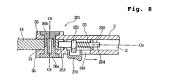
- Fig. 8 shows a holding device 201 according to a third embodiment of the present invention, which is a sectional view taken along the same plane as Fig. 4.
- the holding device 201 only the locking member and the operating member have different constructions from those of the holding device 1 of the first embodiment, but the other portions have the same constructions as those of the holding device 1. Therefore, the detailed description of the portions having the same constructions as those of the holding device 1 of the first embodiment will be omitted by designating them by the common reference numerals.
- a locking member 250 is provided in the mechanism housing space 2a of the handle 2.
- the locking member 250 has a sliding body 251 axially slidingly supported in the mechanism housing space 2a and a locking projection 253 on the front side for facing the recesses 38a, 38b, 38c, 38d and 38e and the sliding surfaces 39a, 39b, 39c and 39d provided in the rotary portion 31 of the support member 4.
- the locking member 250 also has a guide shaft 254 on the rear side, around which the compression coil spring 55 is provided, so that the locking member 250 is always biased forwardly of the handle 2 due to the spring force of the compression coil spring 55.
- the locking member 250 is provided along with a sliding button 270 as operating member.
- the sliding button 270 may be integral with or separate from the locking member 250.
- the sliding button 270 projects out of the handle 2 through the operating hole 243 so that the sliding operation of the sliding button 270 can be performed from outside the handle 2.
- the sliding button 270 is separate from the locking member 250, as the sliding button 270 is slid in the direction of the arrow, the locking member 250 is moved in the direction of the arrow with pressed by the sliding button 270. In this case, the locking member 250 and the sliding button 270 are directly or indirectly engaged together through appropriate means.
- the engagement and fixation of the locking projection to one of the recesses 38a, 38b, 38c, 38d and 38e can be released by operating the push button or the sliding button, and subsequently, the locking projection sliding on one of the sliding surfaces 39a, 39b, 39c and 39d can automatically fit in the adjacent recess.
- the position of the support member 4 can be easily changed, and the support member 4 can be always stabilized in one of the positions (i), (ii), (iii), (iv) and (v) by letting the locking projection fit in one of the recesses 38a, 38b, 38c, 38d and 38e.
- the locking mechanism since the locking mechanism is housed in the mechanism housing space of the handle so that only the push button or the sliding button projects beyond the outer periphery of the handle, the locking mechanism does not appear on the outer periphery of the handle to provide a compact appearance.
- the locking member since the locking member is provided axially movably in the handle, the locking mechanism can be housed in a thin handle. If the operating member is the push button 70 to be operated by pushing in a direction perpendicularly intersecting the shaft axis Os as shown in Figs. 3 and 7, it can be operated easily. If the operating member is the sliding button 270 to be operated by sliding in the same direction as the locking member as shown in Fig. 8, on the other hand, the locking mechanism can be made more simple to make the handle much thinner.
- the locking projection of the locking member can be made thicker within the inner diameter of the handle.
- the recesses 38a-38e of the rotary portion 31 can be of an increased width in the X-direction, the strength of engagement and fixation when the locking projection fits in one of the recesses 38a, 38b, 38c, 38d and 38e can be increased.
- the shaft axis Os of the handle and the pivot axis Or of the support member have been described as perpendicularly intersecting each other in the foregoing embodiments, the axes Os and Or need not intersect each other exactly perpendicularly, as well as a plane inclusive of the axis Os and a plane inclusive of the axis Or need not be common.
- the width of the recesses 38a, 38b, 38c, 38d and 38e formed in the rotary portion 31 may be constant in a direction normal to the pivot axis Or or may be radially increased in the normal direction.
- the locking projection of the locking member may be of any shape as long as can enter the recesses 38a, 38b, 38c, 38d and 38e to stabilize the support member 4.
- the width of the recesses 38a, 38b, 38c, 38d and 38e is radially increased as set forth above and that the locking projection is in the shape of a square rod, because the locking projection subjected to the spring force of the compression coil spring 55 can be certainly brought into contact with the slopes of the recesses 38a, 38b, 38c, 38d and 38e, so that the support member 4 can be certainly engaged and fixed through the locking projection.
- the angle between the first recess 38a and the second recess 38b, the angle between the first recess 38a and the third recess 38c, and the angle between the third recess 38c and the fourth recess 38d are all ⁇ 1 (45 degrees), but these angles between the recesses need not be equal and the angle ⁇ 1 need not be 45 degrees.
- At least a few of components constituting the handle 2, 102, the housing handle 3, the pivot connection 5 and the locking mechanism 6, 106 may be made of metal such as aluminum or alloy such as aluminum alloy, instead of synthetic resin.
- the position of the support member to which a cleaning wiper is to be attached can be changed with a simple operation.
- the support member can be stabilized in predetermined positions without causing unexpected turn.
Landscapes
- Engineering & Computer Science (AREA)
- Mechanical Engineering (AREA)
- Cleaning Implements For Floors, Carpets, Furniture, Walls, And The Like (AREA)
Applications Claiming Priority (3)
| Application Number | Priority Date | Filing Date | Title |
|---|---|---|---|
| JP2002212532 | 2002-07-22 | ||
| JP2002212532A JP4041706B2 (ja) | 2002-07-22 | 2002-07-22 | 清掃用保持具およびその清掃用保持具を用いた清掃物品 |
| PCT/JP2003/009156 WO2004008935A1 (fr) | 2002-07-22 | 2003-07-18 | Support et article nettoyant utilisant ledit support |
Publications (3)
| Publication Number | Publication Date |
|---|---|
| EP1523919A1 true EP1523919A1 (fr) | 2005-04-20 |
| EP1523919A4 EP1523919A4 (fr) | 2008-09-17 |
| EP1523919B1 EP1523919B1 (fr) | 2010-11-17 |
Family
ID=30767810
Family Applications (1)
| Application Number | Title | Priority Date | Filing Date |
|---|---|---|---|
| EP03741481A Expired - Lifetime EP1523919B1 (fr) | 2002-07-22 | 2003-07-18 | Support et article nettoyant utilisant ledit support |
Country Status (16)
| Country | Link |
|---|---|
| US (1) | US7293317B2 (fr) |
| EP (1) | EP1523919B1 (fr) |
| JP (1) | JP4041706B2 (fr) |
| KR (1) | KR101004306B1 (fr) |
| CN (1) | CN1306904C (fr) |
| AR (1) | AR040609A1 (fr) |
| AT (1) | ATE488169T1 (fr) |
| AU (1) | AU2003281463B2 (fr) |
| CA (1) | CA2492582C (fr) |
| DE (1) | DE60334993D1 (fr) |
| EG (1) | EG24557A (fr) |
| ES (1) | ES2355720T3 (fr) |
| MX (1) | MXPA05000910A (fr) |
| MY (1) | MY169757A (fr) |
| TW (1) | TWI273901B (fr) |
| WO (1) | WO2004008935A1 (fr) |
Cited By (10)
| Publication number | Priority date | Publication date | Assignee | Title |
|---|---|---|---|---|
| WO2007044249A1 (fr) * | 2005-09-30 | 2007-04-19 | S. C. Johnson & Son, Inc. | Instrument de nettoyage extensible presentant deux tetes de support |
| WO2008002429A1 (fr) * | 2006-06-26 | 2008-01-03 | S. C. Johnson & Son, Inc. | Tampon de nettoyage ou d'époussetage sans franges |
| WO2008048608A2 (fr) * | 2006-10-18 | 2008-04-24 | S. C. Jonhson & Son, Inc. | Outil de nettoyage souple avec tampon non tissé remplaçable et réservoir de liquide de nettoyage |
| EP2174577A1 (fr) * | 2007-08-01 | 2010-04-14 | Kao Corporation | Outil de nettoyage, et outil en forme de baguette |
| US7740412B2 (en) | 2005-01-28 | 2010-06-22 | S.C. Johnson & Son, Inc. | Method of cleaning using a device with a liquid reservoir and replaceable non-woven pad |
| US7886396B2 (en) | 2004-12-14 | 2011-02-15 | S.C. Johnson & Son, Inc. | Adjustable holder for cleaning implement having two support heads |
| US7976235B2 (en) | 2005-01-28 | 2011-07-12 | S.C. Johnson & Son, Inc. | Cleaning kit including duster and spray |
| ITPD20120137A1 (it) * | 2012-05-04 | 2013-11-05 | T T S S R L Tecno Trolley System | Base per mop dotata di limitatore di rotazione |
| US8893347B2 (en) | 2007-02-06 | 2014-11-25 | S.C. Johnson & Son, Inc. | Cleaning or dusting pad with attachment member holder |
| ITMI20131818A1 (it) * | 2013-11-04 | 2015-05-05 | Nespoli Group S P A | Dispositivo per la rimozione di peli, pelucchi ed altro da tessuti e/o indumenti |
Families Citing this family (71)
| Publication number | Priority date | Publication date | Assignee | Title |
|---|---|---|---|---|
| JP4463062B2 (ja) * | 2004-09-30 | 2010-05-12 | リョービ株式会社 | 作業機 |
| JP4785369B2 (ja) | 2004-11-16 | 2011-10-05 | ユニ・チャーム株式会社 | 清掃用物品 |
| TWM272500U (en) * | 2004-12-22 | 2005-08-11 | Rock Tone Entpr Co Ltd | Dust removal whisk structure |
| US20060171767A1 (en) * | 2005-01-28 | 2006-08-03 | Hoadley David A | Cleaning device with liquid reservoir and replaceable non-woven pad |
| US8931971B2 (en) * | 2005-01-28 | 2015-01-13 | S.C. Johnson & Son, Inc. | Cleaning pad impregnated with a volatile liquid for improved dust adhesion |
| US7566671B2 (en) * | 2005-01-28 | 2009-07-28 | S.C. Johnson & Son, Inc. | Cleaning or dusting pad |
| SE530086C2 (sv) * | 2005-06-30 | 2008-02-26 | Haakan Kronogaard | Redskap samt förfarande för dess användning |
| CA2625482C (fr) * | 2005-10-19 | 2014-01-21 | Kao Corporation | Outil de nettoyage |
| JP4657075B2 (ja) * | 2005-10-21 | 2011-03-23 | 花王株式会社 | 清掃用物品 |
| ES2397856T3 (es) * | 2006-03-09 | 2013-03-11 | Kao Corporation | Artículo de limpieza y método de producción |
| US7574768B2 (en) * | 2006-07-18 | 2009-08-18 | Kimberly-Clark Worldwide, Inc. | Quick-release handle and interchangeable cleaning system |
| US7735182B2 (en) * | 2006-07-18 | 2010-06-15 | Kimberly-Clark Worldwide, Inc. | Mop assembly with reversible head |
| US7624468B2 (en) * | 2006-07-18 | 2009-12-01 | Kimberly-Clark Worldwide, Inc. | Wet mop with multi-layer substrate |
| US7650665B2 (en) | 2006-07-18 | 2010-01-26 | Kimberly-Clark Worlwide, Inc. | Mop assembly with fastener channels |
| US20080052856A1 (en) * | 2006-08-31 | 2008-03-06 | George Lin | Angle-adjustable bath brush |
| JP4976211B2 (ja) * | 2007-06-20 | 2012-07-18 | ユニ・チャーム株式会社 | 清掃用具 |
| ITMO20070215A1 (it) * | 2007-06-22 | 2008-12-23 | Nuova F Lli Dondi S R L | Attrezzo per pulire superfici |
| JP5001079B2 (ja) * | 2007-07-10 | 2012-08-15 | 花王株式会社 | 清掃具 |
| JP5119069B2 (ja) * | 2008-07-11 | 2013-01-16 | キクロン株式会社 | 清掃具取り付け構造 |
| US8578564B2 (en) | 2009-11-05 | 2013-11-12 | The Procter & Gamble Company | Handle for removable cleaning implement |
| EP3539439B1 (fr) * | 2010-04-29 | 2022-06-08 | Diversey, Inc. | Outil et procédé de nettoyage de sol |
| JP5606397B2 (ja) * | 2011-05-31 | 2014-10-15 | 株式会社オーエ | 清掃具 |
| CN103040420B (zh) * | 2011-10-17 | 2015-11-25 | 杨雅菁 | 折叠式除尘掸 |
| US9408522B2 (en) * | 2012-03-09 | 2016-08-09 | 3M Innovative Properties Company | Fryer cleaning tool with cleaning head with cleaning pad slidably mountable thereon |
| TW201340926A (zh) * | 2012-04-13 | 2013-10-16 | Ya-Jing Yang | 自動對摺變長變短的除塵撢手柄 |
| CN104540670B (zh) | 2012-06-18 | 2017-03-29 | 约翰逊父子公司 | 清洁工具 |
| US9775486B2 (en) | 2012-11-09 | 2017-10-03 | 3M Innovative Properties Company | Cleaning pad with support body |
| CN103022079B (zh) | 2012-12-12 | 2015-05-20 | 京东方科技集团股份有限公司 | 阵列基板及其制备方法、有机发光二极管显示装置 |
| TWI576079B (zh) * | 2013-03-28 | 2017-04-01 | Oimo Ind Co Ltd | Three-dimensional cyclone dust |
| US9255369B2 (en) * | 2013-11-01 | 2016-02-09 | Black Diamond Equipment, Ltd. | Collapsable shovel handle |
| USD779143S1 (en) | 2014-04-25 | 2017-02-14 | Unger Marketing International, Llc | Window scraper |
| EP2995321B1 (fr) | 2014-09-15 | 2017-07-26 | Procter & Gamble International Operations SA | Produit de biens de consommation contenant des nanofibrilles de chitine, de la lignine et un polymère ou copolymère |
| US20160106294A1 (en) | 2014-10-16 | 2016-04-21 | The Procter & Gamble Company | Kit having a package containing cleaning implements, package therefor and blank therefor |
| US10575703B2 (en) | 2015-04-29 | 2020-03-03 | Unger Marketing International, Llc | Versatile cleaning devices |
| USD782271S1 (en) | 2015-04-29 | 2017-03-28 | Unger Marketing International, Llc | Tool handle |
| KR101686044B1 (ko) * | 2015-07-14 | 2016-12-13 | 신만철 | 청소용 밀대 |
| CN204889883U (zh) * | 2015-07-27 | 2015-12-23 | 嘉兴捷顺旅游制品有限公司 | 平板拖把 |
| JP6490537B2 (ja) * | 2015-08-21 | 2019-03-27 | 株式会社ダスキン | 片側押ボタン型払拭体保持具及び清掃具 |
| JP6588805B2 (ja) * | 2015-11-10 | 2019-10-09 | 株式会社アイセン | 折り畳み式清掃具 |
| JP6588811B2 (ja) * | 2015-12-07 | 2019-10-09 | 株式会社アイセン | 二部材連結構造及びそれを用いた清掃具 |
| EP3390718B1 (fr) | 2015-12-15 | 2021-03-03 | The Procter and Gamble Company | Structures fibreuses comprenant des zones présentant différents niveaux d'additifs solides |
| WO2017106417A1 (fr) | 2015-12-15 | 2017-06-22 | The Procter & Gamble Company | Structures fibreuses pre-humidifiées présentant une capacité accrue |
| EP3702527B1 (fr) | 2015-12-15 | 2021-10-27 | The Procter & Gamble Company | Structures fibreuses comprenant des régions présentant différentes valeurs de propriété intensives micro-ct et pentes de transition associées |
| EP3390722B1 (fr) | 2015-12-15 | 2020-07-15 | The Procter and Gamble Company | Structures fibreuses comprenant au moins trois zones |
| WO2017106421A2 (fr) | 2015-12-15 | 2017-06-22 | The Procter & Gamble Company | Structures fibreuses préhumidifiées |
| WO2017106416A1 (fr) | 2015-12-15 | 2017-06-22 | The Procter & Gamble Company | Structures fibreuses préhumidifiées à longévité accrue |
| WO2017106422A1 (fr) | 2015-12-15 | 2017-06-22 | The Procter & Gamble Company | Structures fibreuses préhumidifiées compressibles |
| US9963230B2 (en) | 2016-01-11 | 2018-05-08 | The Procter & Gamble Company | Aerial drone cleaning device and method of cleaning a target surface therewith |
| BR112018016788A2 (pt) * | 2016-02-17 | 2018-12-26 | Ecolab Usa Inc | ferramenta de limpeza. |
| KR101769706B1 (ko) | 2016-03-14 | 2017-08-21 | 신만철 | 청소용 밀대 |
| WO2017160901A1 (fr) | 2016-03-15 | 2017-09-21 | The Procter & Gamble Company | Procédé et appareil de fabrication d'un article absorbant comprenant une source laser à impulsions ultracourtes |
| EP3429526B1 (fr) | 2016-03-15 | 2019-12-18 | The Procter and Gamble Company | Procédé et appareil de fabrication d'un article absorbant comprenant une source laser à impulsions ultracourtes |
| US20170266056A1 (en) | 2016-03-15 | 2017-09-21 | The Procter & Gamble Company | Method and Apparatus for Manufacturing an Absorbent Article Including an Ultra Short Pulse Laser Source |
| US11172803B2 (en) | 2016-08-12 | 2021-11-16 | The Procter & Gamble Company | Cleaning sheets having coating thereon |
| EP3551150A1 (fr) | 2016-12-08 | 2019-10-16 | The Procter and Gamble Company | Structures fibreuses dotées d'une surface de contact |
| CA3043530C (fr) | 2016-12-08 | 2021-06-01 | The Procter & Gamble Company | Tampon de nettoyage possedant des structures fibreuses a coeur fendu |
| EP3551022B1 (fr) | 2016-12-08 | 2022-11-23 | The Procter & Gamble Company | Serpillère de nettoyage humidifiée |
| US10759153B2 (en) | 2017-12-07 | 2020-09-01 | The Procter & Gamble Company | Flexible bonding |
| WO2019133497A1 (fr) * | 2017-12-27 | 2019-07-04 | Sharkninja Operating Llc | Appareil de nettoyage avec unité de peignage sélectionnable permettant de retirer des débris d'un rouleau de nettoyage |
| JP6567116B1 (ja) | 2018-03-20 | 2019-08-28 | ユニ・チャーム株式会社 | 清掃具用のアーム部 |
| JP7008553B2 (ja) * | 2018-03-20 | 2022-01-25 | ユニ・チャーム株式会社 | 清掃具 |
| CN108406676B (zh) * | 2018-03-30 | 2023-09-08 | 钦州学院 | 一种基于船舶基座垫块的研配方法 |
| US11135707B2 (en) * | 2018-04-26 | 2021-10-05 | Hersh Designs LLC | Wrench assembly |
| US11576550B2 (en) | 2018-05-29 | 2023-02-14 | Unger Marketing International, Llc | Flat headed mop |
| US11389986B2 (en) | 2018-12-06 | 2022-07-19 | The Procter & Gamble Company | Compliant anvil |
| USD922712S1 (en) | 2019-01-28 | 2021-06-15 | Unger Marketing International, Llc | Flat headed mop |
| USD923896S1 (en) | 2019-05-28 | 2021-06-29 | Unger Marketing International, Llc | Floor cleaning system |
| USD915703S1 (en) | 2019-05-28 | 2021-04-06 | Unger Marketng International, Llc | Flat headed mop |
| DE102020108193A1 (de) * | 2020-03-25 | 2021-09-30 | Airbus Operations Gmbh | Mehrzweckwerkzeug für Flugbegleiter |
| US11219995B1 (en) * | 2020-10-29 | 2022-01-11 | Lone Star College System District | Pivoting assembly, tool, and method of use |
| KR102349700B1 (ko) * | 2020-12-14 | 2022-01-12 | 정연우 | 다용도 청소장치 |
Citations (7)
| Publication number | Priority date | Publication date | Assignee | Title |
|---|---|---|---|---|
| US612491A (en) * | 1898-10-18 | John j | ||
| US881782A (en) * | 1907-04-24 | 1908-03-10 | George F Elliott | Intrenching-tool. |
| US5414889A (en) * | 1994-01-14 | 1995-05-16 | M. B. Walton, Inc. | Broom with position-maintaining multi-angle handle interconnector |
| JPH09154791A (ja) * | 1995-12-08 | 1997-06-17 | Kao Corp | 清掃布及び清掃具 |
| US5862723A (en) * | 1997-06-20 | 1999-01-26 | Rowlands; Albert J. | Pivot head wrench |
| US6315341B1 (en) * | 2000-08-11 | 2001-11-13 | Sandra Leon | Shovel having an adjustable blade angle |
| JP2002017640A (ja) * | 2000-07-04 | 2002-01-22 | Teramoto Corp | 清掃用具のヘッドホルダ |
Family Cites Families (19)
| Publication number | Priority date | Publication date | Assignee | Title |
|---|---|---|---|---|
| US357408A (en) * | 1887-02-08 | Spade | ||
| US261894A (en) * | 1882-08-01 | Manure-fork | ||
| US1427865A (en) * | 1921-11-22 | 1922-09-05 | Szabo Joseph | Digging implement |
| US1570189A (en) * | 1924-12-17 | 1926-01-19 | Sturm John Simon | Adjustable shovel |
| US2740146A (en) * | 1953-06-09 | 1956-04-03 | Sidney P Vaughn | Sponge mop with adjustable handle and squeezer means |
| JPS5185273A (ja) * | 1975-01-22 | 1976-07-26 | Takeshi Abiru | Burashihorudaa |
| JPS5340271A (en) | 1976-09-27 | 1978-04-12 | Hitachi Ltd | Semiconductor diffusing method |
| CN85202172U (zh) * | 1985-06-11 | 1986-03-26 | 郭家明 | 多功能清洁器 |
| US4658461A (en) * | 1985-10-02 | 1987-04-21 | The Wooster Brush Company | Flat pad applicator |
| JPH0361057U (fr) * | 1989-10-17 | 1991-06-14 | ||
| US5110230A (en) * | 1991-02-22 | 1992-05-05 | Cole Jr Mark F | Adjustable swimming-pool cleaning tool |
| CN2164785Y (zh) * | 1993-04-13 | 1994-05-18 | 李志明 | 多功能清洁擦 |
| JPH0938009A (ja) | 1995-08-01 | 1997-02-10 | Kao Corp | 清掃布、清掃具の柄及び清掃具 |
| JPH1043116A (ja) | 1996-08-05 | 1998-02-17 | Kao Corp | 清掃具の柄 |
| JPH10309251A (ja) * | 1997-05-13 | 1998-11-24 | Lion Corp | 掃除具 |
| US5926896A (en) * | 1997-11-25 | 1999-07-27 | Rubbermaid Commercial Products Llc | Collapsible cleaning implement |
| CA2229825A1 (fr) * | 1998-02-18 | 1999-08-18 | Chia-Hao Wu | Brosse multi-fonctions pour le dos |
| JP3061057U (ja) * | 1999-01-27 | 1999-09-14 | 株式会社東北石橋 | 自在ヘッド形式の柄付きブラシ |
| JP4643819B2 (ja) * | 2000-12-11 | 2011-03-02 | 株式会社ダスキン | 柄付モップ把持具 |
-
2002
- 2002-07-22 JP JP2002212532A patent/JP4041706B2/ja not_active Expired - Lifetime
-
2003
- 2003-07-14 TW TW092119159A patent/TWI273901B/zh not_active IP Right Cessation
- 2003-07-17 MY MYPI20032694A patent/MY169757A/en unknown
- 2003-07-18 AT AT03741481T patent/ATE488169T1/de not_active IP Right Cessation
- 2003-07-18 EP EP03741481A patent/EP1523919B1/fr not_active Expired - Lifetime
- 2003-07-18 KR KR1020057001090A patent/KR101004306B1/ko active IP Right Grant
- 2003-07-18 CA CA002492582A patent/CA2492582C/fr not_active Expired - Lifetime
- 2003-07-18 ES ES03741481T patent/ES2355720T3/es not_active Expired - Lifetime
- 2003-07-18 WO PCT/JP2003/009156 patent/WO2004008935A1/fr active Application Filing
- 2003-07-18 CN CNB038164426A patent/CN1306904C/zh not_active Expired - Fee Related
- 2003-07-18 MX MXPA05000910A patent/MXPA05000910A/es active IP Right Grant
- 2003-07-18 DE DE60334993T patent/DE60334993D1/de not_active Expired - Lifetime
- 2003-07-18 AU AU2003281463A patent/AU2003281463B2/en not_active Ceased
- 2003-07-21 AR AR20030102611A patent/AR040609A1/es active IP Right Grant
- 2003-07-22 EG EG2003070713A patent/EG24557A/xx active
-
2004
- 2004-12-14 US US11/012,949 patent/US7293317B2/en not_active Expired - Fee Related
Patent Citations (7)
| Publication number | Priority date | Publication date | Assignee | Title |
|---|---|---|---|---|
| US612491A (en) * | 1898-10-18 | John j | ||
| US881782A (en) * | 1907-04-24 | 1908-03-10 | George F Elliott | Intrenching-tool. |
| US5414889A (en) * | 1994-01-14 | 1995-05-16 | M. B. Walton, Inc. | Broom with position-maintaining multi-angle handle interconnector |
| JPH09154791A (ja) * | 1995-12-08 | 1997-06-17 | Kao Corp | 清掃布及び清掃具 |
| US5862723A (en) * | 1997-06-20 | 1999-01-26 | Rowlands; Albert J. | Pivot head wrench |
| JP2002017640A (ja) * | 2000-07-04 | 2002-01-22 | Teramoto Corp | 清掃用具のヘッドホルダ |
| US6315341B1 (en) * | 2000-08-11 | 2001-11-13 | Sandra Leon | Shovel having an adjustable blade angle |
Non-Patent Citations (1)
| Title |
|---|
| See also references of WO2004008935A1 * |
Cited By (19)
| Publication number | Priority date | Publication date | Assignee | Title |
|---|---|---|---|---|
| US7802340B2 (en) | 2004-12-14 | 2010-09-28 | S.C. Johnson & Son, Inc. | Extendable cleaning implement having two support heads |
| US7886396B2 (en) | 2004-12-14 | 2011-02-15 | S.C. Johnson & Son, Inc. | Adjustable holder for cleaning implement having two support heads |
| US8657515B2 (en) | 2005-01-28 | 2014-02-25 | S.C. Johnson & Son, Inc. | Cleaning kit including duster and spray |
| US7740412B2 (en) | 2005-01-28 | 2010-06-22 | S.C. Johnson & Son, Inc. | Method of cleaning using a device with a liquid reservoir and replaceable non-woven pad |
| US7891898B2 (en) | 2005-01-28 | 2011-02-22 | S.C. Johnson & Son, Inc. | Cleaning pad for wet, damp or dry cleaning |
| US7976235B2 (en) | 2005-01-28 | 2011-07-12 | S.C. Johnson & Son, Inc. | Cleaning kit including duster and spray |
| WO2007044249A1 (fr) * | 2005-09-30 | 2007-04-19 | S. C. Johnson & Son, Inc. | Instrument de nettoyage extensible presentant deux tetes de support |
| WO2008002429A1 (fr) * | 2006-06-26 | 2008-01-03 | S. C. Johnson & Son, Inc. | Tampon de nettoyage ou d'époussetage sans franges |
| WO2008048608A2 (fr) * | 2006-10-18 | 2008-04-24 | S. C. Jonhson & Son, Inc. | Outil de nettoyage souple avec tampon non tissé remplaçable et réservoir de liquide de nettoyage |
| WO2008048608A3 (fr) * | 2006-10-18 | 2008-06-12 | S C Jonhson & Son Inc | Outil de nettoyage souple avec tampon non tissé remplaçable et réservoir de liquide de nettoyage |
| US8893347B2 (en) | 2007-02-06 | 2014-11-25 | S.C. Johnson & Son, Inc. | Cleaning or dusting pad with attachment member holder |
| EP2174577A1 (fr) * | 2007-08-01 | 2010-04-14 | Kao Corporation | Outil de nettoyage, et outil en forme de baguette |
| US8595884B2 (en) | 2007-08-01 | 2013-12-03 | Kao Corporation | Cleaning tool and stick-like tool |
| US8813298B2 (en) | 2007-08-01 | 2014-08-26 | Kao Corporation | Cleaning tool and stick-like tool |
| EP2174577A4 (fr) * | 2007-08-01 | 2010-12-15 | Kao Corp | Outil de nettoyage, et outil en forme de baguette |
| WO2013164800A1 (fr) * | 2012-05-04 | 2013-11-07 | T.T.S. S.R.L. | Base de balai-éponge pourvue d'un limiteur de rotation articulé |
| ITPD20120137A1 (it) * | 2012-05-04 | 2013-11-05 | T T S S R L Tecno Trolley System | Base per mop dotata di limitatore di rotazione |
| RU2598144C2 (ru) * | 2012-05-04 | 2016-09-20 | Т.Т.С. С.Р.Л. | Основа швабры с шарнирным ограничителем вращения |
| ITMI20131818A1 (it) * | 2013-11-04 | 2015-05-05 | Nespoli Group S P A | Dispositivo per la rimozione di peli, pelucchi ed altro da tessuti e/o indumenti |
Also Published As
| Publication number | Publication date |
|---|---|
| CA2492582C (fr) | 2008-07-29 |
| EP1523919B1 (fr) | 2010-11-17 |
| MY169757A (en) | 2019-05-15 |
| KR101004306B1 (ko) | 2010-12-28 |
| TWI273901B (en) | 2007-02-21 |
| CA2492582A1 (fr) | 2004-01-29 |
| JP2004049619A (ja) | 2004-02-19 |
| AU2003281463A1 (en) | 2004-02-09 |
| EG24557A (en) | 2009-10-12 |
| US20050102781A1 (en) | 2005-05-19 |
| DE60334993D1 (de) | 2010-12-30 |
| EP1523919A4 (fr) | 2008-09-17 |
| WO2004008935A1 (fr) | 2004-01-29 |
| CN1306904C (zh) | 2007-03-28 |
| TW200401623A (en) | 2004-02-01 |
| AU2003281463B2 (en) | 2009-01-08 |
| ATE488169T1 (de) | 2010-12-15 |
| JP4041706B2 (ja) | 2008-01-30 |
| CN1668240A (zh) | 2005-09-14 |
| AR040609A1 (es) | 2005-04-13 |
| KR20050026502A (ko) | 2005-03-15 |
| ES2355720T3 (es) | 2011-03-30 |
| MXPA05000910A (es) | 2005-03-23 |
| US7293317B2 (en) | 2007-11-13 |
Similar Documents
| Publication | Publication Date | Title |
|---|---|---|
| AU2003281463B2 (en) | Holder and cleaning implement using the holder | |
| US8156603B2 (en) | Cleaning tool | |
| US5937471A (en) | Multipurpose floor cleaning device | |
| US7055204B2 (en) | Cleaning device | |
| EP1974648B1 (fr) | Elément de nettoyage et outil de nettoyage | |
| CA2627876A1 (fr) | Element et outil de nettoyage | |
| JP4113740B2 (ja) | 清掃用保持具およびその清掃用保持具を用いた清掃物品 | |
| JP6656880B2 (ja) | カバー付き清掃具のカバー開閉方法及びカバー付き清掃具 | |
| JP2006141623A (ja) | クリップ | |
| JP6490537B2 (ja) | 片側押ボタン型払拭体保持具及び清掃具 | |
| JP3182554B2 (ja) | 髪梳き用剃刀の替え刃と髪梳き用剃刀 | |
| JP2002017640A (ja) | 清掃用具のヘッドホルダ | |
| JP2010274026A (ja) | モップ、およびモップと収容ケースとのセット | |
| JP5961425B2 (ja) | 清掃体ホルダ、清掃用具 | |
| JP2007068772A (ja) | 清掃具 | |
| JP5114231B2 (ja) | 清掃部材、およびこの清掃部材を備えた清掃具 | |
| JP2001218719A (ja) | 柄付きモップ把持具 | |
| JP3208914U (ja) | 綴じ具及びそれを備えたファイル | |
| JPH081906Y2 (ja) | ファイル用綴込用具 | |
| JP2003135354A (ja) | 清掃具 | |
| JP2023037164A (ja) | ちりとり | |
| JP3105597U (ja) | ブラシ | |
| CN113840563A (zh) | 清扫工具 | |
| JP2020188823A (ja) | 清掃具 | |
| JP2001341481A (ja) | 綴じ具 |
Legal Events
| Date | Code | Title | Description |
|---|---|---|---|
| PUAI | Public reference made under article 153(3) epc to a published international application that has entered the european phase |
Free format text: ORIGINAL CODE: 0009012 |
|
| 17P | Request for examination filed |
Effective date: 20041209 |
|
| AK | Designated contracting states |
Kind code of ref document: A1 Designated state(s): AT BE BG CH CY CZ DE DK EE ES FI FR GB GR HU IE IT LI LU MC NL PT RO SE SI SK TR |
|
| AX | Request for extension of the european patent |
Extension state: AL LT LV MK |
|
| DAX | Request for extension of the european patent (deleted) | ||
| A4 | Supplementary search report drawn up and despatched |
Effective date: 20080819 |
|
| 17Q | First examination report despatched |
Effective date: 20081111 |
|
| GRAP | Despatch of communication of intention to grant a patent |
Free format text: ORIGINAL CODE: EPIDOSNIGR1 |
|
| GRAS | Grant fee paid |
Free format text: ORIGINAL CODE: EPIDOSNIGR3 |
|
| GRAA | (expected) grant |
Free format text: ORIGINAL CODE: 0009210 |
|
| AK | Designated contracting states |
Kind code of ref document: B1 Designated state(s): AT BE BG CH CY CZ DE DK EE ES FI FR GB GR HU IE IT LI LU MC NL PT RO SE SI SK TR |
|
| REG | Reference to a national code |
Ref country code: GB Ref legal event code: FG4D |
|
| REG | Reference to a national code |
Ref country code: CH Ref legal event code: EP |
|
| REG | Reference to a national code |
Ref country code: IE Ref legal event code: FG4D |
|
| REF | Corresponds to: |
Ref document number: 60334993 Country of ref document: DE Date of ref document: 20101230 Kind code of ref document: P |
|
| REG | Reference to a national code |
Ref country code: NL Ref legal event code: T3 |
|
| REG | Reference to a national code |
Ref country code: ES Ref legal event code: FG2A Ref document number: 2355720 Country of ref document: ES Kind code of ref document: T3 Effective date: 20110330 |
|
| REG | Reference to a national code |
Ref country code: SK Ref legal event code: T3 Ref document number: E 8580 Country of ref document: SK |
|
| PG25 | Lapsed in a contracting state [announced via postgrant information from national office to epo] |
Ref country code: BG Free format text: LAPSE BECAUSE OF FAILURE TO SUBMIT A TRANSLATION OF THE DESCRIPTION OR TO PAY THE FEE WITHIN THE PRESCRIBED TIME-LIMIT Effective date: 20110217 Ref country code: PT Free format text: LAPSE BECAUSE OF FAILURE TO SUBMIT A TRANSLATION OF THE DESCRIPTION OR TO PAY THE FEE WITHIN THE PRESCRIBED TIME-LIMIT Effective date: 20110317 Ref country code: SI Free format text: LAPSE BECAUSE OF FAILURE TO SUBMIT A TRANSLATION OF THE DESCRIPTION OR TO PAY THE FEE WITHIN THE PRESCRIBED TIME-LIMIT Effective date: 20101117 Ref country code: AT Free format text: LAPSE BECAUSE OF FAILURE TO SUBMIT A TRANSLATION OF THE DESCRIPTION OR TO PAY THE FEE WITHIN THE PRESCRIBED TIME-LIMIT Effective date: 20101117 Ref country code: FI Free format text: LAPSE BECAUSE OF FAILURE TO SUBMIT A TRANSLATION OF THE DESCRIPTION OR TO PAY THE FEE WITHIN THE PRESCRIBED TIME-LIMIT Effective date: 20101117 Ref country code: CY Free format text: LAPSE BECAUSE OF FAILURE TO SUBMIT A TRANSLATION OF THE DESCRIPTION OR TO PAY THE FEE WITHIN THE PRESCRIBED TIME-LIMIT Effective date: 20101117 Ref country code: SE Free format text: LAPSE BECAUSE OF FAILURE TO SUBMIT A TRANSLATION OF THE DESCRIPTION OR TO PAY THE FEE WITHIN THE PRESCRIBED TIME-LIMIT Effective date: 20101117 |
|
| REG | Reference to a national code |
Ref country code: HU Ref legal event code: AG4A Ref document number: E010189 Country of ref document: HU |
|
| PG25 | Lapsed in a contracting state [announced via postgrant information from national office to epo] |
Ref country code: EE Free format text: LAPSE BECAUSE OF FAILURE TO SUBMIT A TRANSLATION OF THE DESCRIPTION OR TO PAY THE FEE WITHIN THE PRESCRIBED TIME-LIMIT Effective date: 20101117 |
|
| PG25 | Lapsed in a contracting state [announced via postgrant information from national office to epo] |
Ref country code: RO Free format text: LAPSE BECAUSE OF FAILURE TO SUBMIT A TRANSLATION OF THE DESCRIPTION OR TO PAY THE FEE WITHIN THE PRESCRIBED TIME-LIMIT Effective date: 20101117 Ref country code: DK Free format text: LAPSE BECAUSE OF FAILURE TO SUBMIT A TRANSLATION OF THE DESCRIPTION OR TO PAY THE FEE WITHIN THE PRESCRIBED TIME-LIMIT Effective date: 20101117 |
|
| PLBE | No opposition filed within time limit |
Free format text: ORIGINAL CODE: 0009261 |
|
| STAA | Information on the status of an ep patent application or granted ep patent |
Free format text: STATUS: NO OPPOSITION FILED WITHIN TIME LIMIT |
|
| 26N | No opposition filed |
Effective date: 20110818 |
|
| REG | Reference to a national code |
Ref country code: DE Ref legal event code: R097 Ref document number: 60334993 Country of ref document: DE Effective date: 20110818 |
|
| PG25 | Lapsed in a contracting state [announced via postgrant information from national office to epo] |
Ref country code: MC Free format text: LAPSE BECAUSE OF NON-PAYMENT OF DUE FEES Effective date: 20110731 |
|
| REG | Reference to a national code |
Ref country code: CH Ref legal event code: PL |
|
| PG25 | Lapsed in a contracting state [announced via postgrant information from national office to epo] |
Ref country code: CH Free format text: LAPSE BECAUSE OF NON-PAYMENT OF DUE FEES Effective date: 20110731 Ref country code: LI Free format text: LAPSE BECAUSE OF NON-PAYMENT OF DUE FEES Effective date: 20110731 |
|
| PG25 | Lapsed in a contracting state [announced via postgrant information from national office to epo] |
Ref country code: TR Free format text: LAPSE BECAUSE OF FAILURE TO SUBMIT A TRANSLATION OF THE DESCRIPTION OR TO PAY THE FEE WITHIN THE PRESCRIBED TIME-LIMIT Effective date: 20101117 |
|
| REG | Reference to a national code |
Ref country code: GR Ref legal event code: EP Ref document number: 20100402950 Country of ref document: GR Effective date: 20110119 |
|
| REG | Reference to a national code |
Ref country code: FR Ref legal event code: PLFP Year of fee payment: 14 |
|
| REG | Reference to a national code |
Ref country code: FR Ref legal event code: PLFP Year of fee payment: 15 |
|
| REG | Reference to a national code |
Ref country code: FR Ref legal event code: PLFP Year of fee payment: 16 |
|
| PGFP | Annual fee paid to national office [announced via postgrant information from national office to epo] |
Ref country code: GR Payment date: 20210611 Year of fee payment: 19 Ref country code: IT Payment date: 20210610 Year of fee payment: 19 Ref country code: NL Payment date: 20210615 Year of fee payment: 19 Ref country code: SK Payment date: 20210615 Year of fee payment: 19 Ref country code: FR Payment date: 20210611 Year of fee payment: 19 Ref country code: CZ Payment date: 20210629 Year of fee payment: 19 |
|
| PGFP | Annual fee paid to national office [announced via postgrant information from national office to epo] |
Ref country code: BE Payment date: 20210617 Year of fee payment: 19 Ref country code: GB Payment date: 20210623 Year of fee payment: 19 |
|
| PGFP | Annual fee paid to national office [announced via postgrant information from national office to epo] |
Ref country code: LU Payment date: 20210712 Year of fee payment: 19 Ref country code: IE Payment date: 20210712 Year of fee payment: 19 |
|
| PGFP | Annual fee paid to national office [announced via postgrant information from national office to epo] |
Ref country code: ES Payment date: 20210804 Year of fee payment: 19 Ref country code: HU Payment date: 20210616 Year of fee payment: 19 Ref country code: DE Payment date: 20210622 Year of fee payment: 19 |
|
| REG | Reference to a national code |
Ref country code: DE Ref legal event code: R119 Ref document number: 60334993 Country of ref document: DE |
|
| REG | Reference to a national code |
Ref country code: NL Ref legal event code: MM Effective date: 20220801 |
|
| REG | Reference to a national code |
Ref country code: SK Ref legal event code: MM4A Ref document number: E 8580 Country of ref document: SK Effective date: 20220718 |
|
| GBPC | Gb: european patent ceased through non-payment of renewal fee |
Effective date: 20220718 |
|
| REG | Reference to a national code |
Ref country code: BE Ref legal event code: MM Effective date: 20220731 |
|
| PG25 | Lapsed in a contracting state [announced via postgrant information from national office to epo] |
Ref country code: LU Free format text: LAPSE BECAUSE OF NON-PAYMENT OF DUE FEES Effective date: 20220718 Ref country code: FR Free format text: LAPSE BECAUSE OF NON-PAYMENT OF DUE FEES Effective date: 20220731 Ref country code: CZ Free format text: LAPSE BECAUSE OF NON-PAYMENT OF DUE FEES Effective date: 20220718 |
|
| PG25 | Lapsed in a contracting state [announced via postgrant information from national office to epo] |
Ref country code: SK Free format text: LAPSE BECAUSE OF NON-PAYMENT OF DUE FEES Effective date: 20220718 Ref country code: HU Free format text: LAPSE BECAUSE OF NON-PAYMENT OF DUE FEES Effective date: 20220719 Ref country code: GR Free format text: LAPSE BECAUSE OF NON-PAYMENT OF DUE FEES Effective date: 20230209 Ref country code: GB Free format text: LAPSE BECAUSE OF NON-PAYMENT OF DUE FEES Effective date: 20220718 Ref country code: DE Free format text: LAPSE BECAUSE OF NON-PAYMENT OF DUE FEES Effective date: 20230201 Ref country code: BE Free format text: LAPSE BECAUSE OF NON-PAYMENT OF DUE FEES Effective date: 20220731 |
|
| PG25 | Lapsed in a contracting state [announced via postgrant information from national office to epo] |
Ref country code: NL Free format text: LAPSE BECAUSE OF NON-PAYMENT OF DUE FEES Effective date: 20220801 |
|
| PG25 | Lapsed in a contracting state [announced via postgrant information from national office to epo] |
Ref country code: IT Free format text: LAPSE BECAUSE OF NON-PAYMENT OF DUE FEES Effective date: 20220718 Ref country code: IE Free format text: LAPSE BECAUSE OF NON-PAYMENT OF DUE FEES Effective date: 20220718 |
|
| REG | Reference to a national code |
Ref country code: ES Ref legal event code: FD2A Effective date: 20230830 |
|
| PG25 | Lapsed in a contracting state [announced via postgrant information from national office to epo] |
Ref country code: ES Free format text: LAPSE BECAUSE OF NON-PAYMENT OF DUE FEES Effective date: 20220719 |