EP1522993B1 - Urträger für magnetische Übertragung - Google Patents
Urträger für magnetische Übertragung Download PDFInfo
- Publication number
- EP1522993B1 EP1522993B1 EP04020418A EP04020418A EP1522993B1 EP 1522993 B1 EP1522993 B1 EP 1522993B1 EP 04020418 A EP04020418 A EP 04020418A EP 04020418 A EP04020418 A EP 04020418A EP 1522993 B1 EP1522993 B1 EP 1522993B1
- Authority
- EP
- European Patent Office
- Prior art keywords
- projection
- master carrier
- magnetic
- transfer
- magnetic recording
- Prior art date
- Legal status (The legal status is an assumption and is not a legal conclusion. Google has not performed a legal analysis and makes no representation as to the accuracy of the status listed.)
- Expired - Lifetime
Links
- 230000005291 magnetic effect Effects 0.000 title claims description 131
- 230000002093 peripheral effect Effects 0.000 claims description 42
- 238000000034 method Methods 0.000 claims description 9
- 239000010410 layer Substances 0.000 description 7
- 230000002459 sustained effect Effects 0.000 description 6
- 239000000969 carrier Substances 0.000 description 5
- 230000015572 biosynthetic process Effects 0.000 description 2
- 230000005294 ferromagnetic effect Effects 0.000 description 2
- 238000004519 manufacturing process Methods 0.000 description 2
- 239000010409 thin film Substances 0.000 description 2
- 230000002708 enhancing effect Effects 0.000 description 1
- 238000012986 modification Methods 0.000 description 1
- 230000004048 modification Effects 0.000 description 1
- 238000000206 photolithography Methods 0.000 description 1
- 239000002344 surface layer Substances 0.000 description 1
- 238000013518 transcription Methods 0.000 description 1
- 230000035897 transcription Effects 0.000 description 1
Images


Classifications
-
- G—PHYSICS
- G11—INFORMATION STORAGE
- G11B—INFORMATION STORAGE BASED ON RELATIVE MOVEMENT BETWEEN RECORD CARRIER AND TRANSDUCER
- G11B5/00—Recording by magnetisation or demagnetisation of a record carrier; Reproducing by magnetic means; Record carriers therefor
- G11B5/86—Re-recording, i.e. transcribing information from one magnetisable record carrier on to one or more similar or dissimilar record carriers
- G11B5/865—Re-recording, i.e. transcribing information from one magnetisable record carrier on to one or more similar or dissimilar record carriers by contact "printing"
Definitions
- the present invention relates to a master carrier for magnetic transfer, which magnetically transfers carried information onto a slave medium that is a magnetic recording medium by being brought into intimate contact with each other.
- a hard disk 1 has a plural number of servo zones 2 where a servo signal is written in the radius direction, and the position adjustment of a recording head 5 provided in the tip of a positioner 4 rotating around an axis 3 is indicated.
- a transfer magnetic field is applied to a master carrier (patterned master), the master carrier having an transfer pattern corresponding to preformat information such as servo signals and having at least a magnetic layer thereon as a surface layer, in the state that the master carrier is brought into intimate contact with a slave medium that is a magnetic recording medium having a magnetic recording part, thereby transferring and recording a magnetic pattern corresponding to the information carried on the master carrier onto the slave medium.
- a master carrier patterned master
- the master carrier having an transfer pattern corresponding to preformat information such as servo signals and having at least a magnetic layer thereon as a surface layer
- a master carrier 6 has a preformat information writing region 7 where a projection transfer pattern corresponding to the preformat information such as a servo signal is formed as described previously, and a magnetic layer is formed on this transfer pattern (for example, see U.S. Patent No.6,347,016 ).
- US 2002/0150794 A1 relates to a master disc and a method for manufacturing a magnetic disc using the same.
- a master disc capable of conducting a preformat-recording by a magnetic transcription without causing any unevenness over an entire magnetic disc is provided.
- the master disc is provided with a radial land portion where an array of ferromagnetic thin films is formed and a concave portion against the land portion.
- a master information carrier includes a high-level region and a low-level region that are formed on a non-magnetic base.
- the high-level region includes a ferromagnetic thin film pattern that corresponds to preformat information signals.
- the master carrier 6 causes deformation in a difference portion in level by projections constructing the transfer pattern of the preformat information writing region 7 of the master carrier 6.
- This difference in level is a boundary portion of the preformat information writing region 7 and is present in not only the peripheral direction but also the inner radius side and the outer radius side in the radius direction of the master carrier 6.
- the surface of the slave medium 8 is damaged by an edge portion of the transfer pattern of the preformat information writing region 7.
- this invention has been made, and its object is to provide a master carrier for magnetic transfer capable of performing magnetic transfer surely by bringing it into intimate contact with a slave medium satisfactorily without causing obstacles such as deformation and damage.
- the master carrier for magnetic transfer of the invention comprises a support having an information writing region where a projection transfer pattern having a first projection corresponding to information to be transferred onto a magnetic recording medium is formed; and a magnetic layer formed on the transfer pattern of the support, the master carrier being constructed such that a second projection is provided on the surface of the support with the exception of the information writing region and that the surface of the support with the exception of the information writing region is sustained by the second projection at the time when the magnetic recording medium and the support are brought into intimate contact with each other.
- first projection as used herein means a projection of the transfer pattern corresponding to information to be transferred onto a magnetic recording medium
- second projection means a projection to be provided to sustain a part of the support.
- this master carrier for magnetic transfer since the surface of the support with the exception of the information writing regions having a projection transfer pattern is sustained by the second projection, the deformation caused by a difference in level as formed in the surrounding of the transfer pattern is prevented. Also, because of the matter that the deformation of the master carrier is prevented, damage caused when an edge portion of the transfer pattern bites into the surface of the magnetic recording medium is prevented.
- the master carrier for magnetic transfer of the invention is characterized in that the upper surface of the second projection is formed so as to have a height the same as the height of the transfer pattern projection from the surface of the support.
- the second projection provided on the surface of the support with the exception of the information writing region has a height the same as the height of the transfer pattern projection from the surface of the support, deformation at the time of magnetic transfer and damage onto the magnetic recording medium caused by the deformation can be prevented more surely.
- the master carrier for magnetic transfer of the invention is characterized in that the second projection is formed in a plural number of lines concentrically or radially against the master carrier, and a depression is provided between the second projections.
- magnetic transfer onto the magnetic recording medium can be performed without causing obstacles such as deformation and damage. Moreover, it is possible to obtain good adhesion to the magnetic recording medium.
- the master carrier for magnetic transfer of the invention is characterized in that the second projection is provided in a plural number of positions in the dispersed state against the surface of the master carrier.
- this master carrier for magnetic transfer obstacles such as deformation and damage at the time of magnetic transfer can be prevented by the second projection. Also, air between the master carrier and the magnetic recording medium is introduced to outside from a space between the second projections, whereby good adhesion can be obtained.
- the master carrier for magnetic transfer of the invention is characterized in that a gap generated by the second projection at the time when it comes into intimate contact with the magnetic recording medium is communicated between the central side and the outer peripheral end of the master carrier.
- magnetic transfer onto the magnetic recording medium can be performed without causing obstacles such as deformation and damage. Moreover, by introducing air to outside, it is possible to obtain good adhesion to the magnetic recording medium.
- the master carrier for magnetic transfer of the invention is characterized in that a plural number of the projections are set up so as to have an alignment pitch of from 0.1 ⁇ m to 1.5 mm.
- magnetic transfer onto the magnetic recording medium can be performed without causing obstacles such as deformation and damage while supporting a region with the exception of the preformat information writing region at a good plane pressure at the time of magnetic transfer. Moreover, it is possible to obtain good adhesion to the magnetic recording medium.
- the master carrier for magnetic transfer of the invention since the surface of the support with the exception of the information writing region having a projection transfer pattern is sustained by the projection, the deformation caused by a difference in level as formed in the surrounding of the transfer pattern is prevented. Also, because of the matter that the deformation of the master carrier is prevented, damage caused when an edge portion of the transfer pattern bites into the surface of the magnetic recording medium is prevented.
- Fig. 1 is a perspective view of a slave medium and a master carrier for explaining the magnetic transfer
- Fig. 2 is a cross-sectional view for explaining the principle of magnetic transfer.
- each of master carriers 100 has a transfer pattern having a projection of a format signal such as a servo signal and a magnetic layer 13 thereon to a surface of a support 11. Further, a transfer magnetic field is applied to the master carriers 100 in the state that they are respectively brought into intimate contact with the front and back surfaces of a slave medium 19 having magnetic recording sections 17 on the front and back surfaces of a support 15, thereby transferring and recording a magnetic pattern corresponding to information carried on each of the master carriers 100 onto the slave medium 19 that is a magnetic recording medium.
- a transfer magnetic field is applied to the master carriers 100 in the state that they are respectively brought into intimate contact with the front and back surfaces of a slave medium 19 having magnetic recording sections 17 on the front and back surfaces of a support 15, thereby transferring and recording a magnetic pattern corresponding to information carried on each of the master carriers 100 onto the slave medium 19 that is a magnetic recording medium.
- the slave medium 19 in which an initial magnetic field Hin going in one direction is previously imparted to the magnetic recording section 17 as shown in Fig. 2A is brought into intimate contact with the master carrier 100 and applied with a transfer magnetic field Hdu as shown in Fig. 2B .
- this transfer magnetic field Hdu is absorbed into the magnetic layer 13 portion of a projection 23 of a transfer pattern 21 with which the slave medium 19 is brought into intimate contact.
- the initial magnetic field Hin of the slave medium 19 in this portion is not reversed, whereas the initial magnetic field Hdu in other portion is reversed.
- a magnetized pattern corresponding to the transfer pattern 21 of the master carrier 100 is transferred and recorded onto the slave medium 19 as shown in Fig. 2C .
- Fig. 3 is a perspective view for explaining the structure of a master carrier according to the First Embodiment.
- this master carrier 100 has a preformat information writing region 25 (hereinafter referred to as "information writing region”) in which a plural number of projection transfer patterns 21 corresponding to the preformat information such as a servo signal are substantially radially formed towards the radius direction, and a space between the information writing regions 25 is defined as a data region 26.
- information writing region a preformat information writing region 25 (hereinafter referred to as "information writing region") in which a plural number of projection transfer patterns 21 corresponding to the preformat information such as a servo signal are substantially radially formed towards the radius direction, and a space between the information writing regions 25 is defined as a data region 26.
- a projection 27 is formed in both or either one of the inner peripheral side and the outer peripheral side of the information writing region 25 (in the drawing, the outer peripheral side is mainly illustrated and explained as one example). That is, the projection 27 is formed on the surface of the support 11 with the exception of the information writing region 25.
- This projection 27 is, for example, formed by a process such as photo-lithography, EB exposure, and laser exposure and is formed integrally with the support 11.
- the projection 27 is positioned adjacent to the transfer pattern 21 of the information writing region 25.
- the upper surface of the projection 27 is formed so as to have a substantially same height as that of the projection 23 of the transfer pattern 21 formed in the information writing region 25, which projects from the surface of the support 11.
- the transfer pattern 21 of the information writing region 25 and the projection 27 of the master carrier 100 come into contact with the slave medium19 as shown in Fig. 4 .
- the projection 27 is constructed such that it does not have a magnetic layer to be formed on the transfer pattern 21, thereby having a non-magnetic surface property, since the magnetic information does not remain in the slave medium 19 after the transfer, it is not necessary to make the drive side to read and write signals take a specific countermeasure. Also, in the case where the projection 27 is made so as to have a magnetic surface property by forming a magnetic layer, it is possible to prepare the projection 27 at the same time with the formation of the transfer pattern 21.
- the master carrier 100 of this Embodiment by bringing the master carrier 100 into intimate contact with the slave medium 19, it is possible to perform magnetic transfer free from signal failure onto the slave medium 19 satisfactorily without causing obstacles such as deformation of the transfer pattern 21 and damage onto the surface of the slave medium 19.
- Fig. 5 is a perspective view of a part of an outer peripheral portion of the master carrier.
- a projection 29 is radially provided in the inner and outer peripheral sides of the information writing region 25.
- the projection 29 is provided and formed in a plural number of lines with a space radially against the peripheral direction, and a depression 31 is provided between the projections 29. Accordingly, for the sake of performing magnetic transfer, when the master carrier 200 and the slave medium 19 are superposed, air between the master carrier 200 and the slave medium 19 is introduced to outside in the depression 31, whereby good adhesion between the master carrier 200 and the slave medium 19 can be obtained.
- this master carrier 200 air between the master carrier 200 and the slave medium 19 can be completely released with good efficiency from the inside to the outside or from the outside to the inside in the radius direction, whereby good adhesion between the master carrier 200 and the slave medium 19 can be obtained rapidly and surely. Accordingly, it is designed to realize tact-up of the treatment. Further, it is possible to perform magnetic transfer with good signal quality onto the slave support 19 without causing obstacles such as deformation and damage.
- the projection 29 provided in the inner and outer peripheral sides of the information writing region 25 is provided continuously in such a manner that it is engaged with the projection 23 of the transfer pattern 21.
- the projection 29 is limited to one in which it is continued to the projection 23 of the transfer pattern 21.
- Fig. 6 is a perspective view of a part of an outer peripheral portion of the master carrier. As shown in Fig. 6 , in this master carrier 210, the projection 29 is discontinued to the projection 23 of the transfer part 21 while providing a gap.
- this master carrier 210 it is also possible to perform magnetic transfer onto the slave medium 19 without causing obstacles such as deformation and damage. Moreover, it is possible to obtain good adhesion to the slave medium 19.
- the master carriers by providing the projection 29 at a pitch the same as in the projection 23 of the transfer pattern 21, these master carriers are constructed in such a manner that the projection 29 can be simply formed at the same time with the formation of the transfer pattern 21.
- the invention is not limited thereto.
- a pitch between the projections 29 may be deviated from that between the projections 23 of the transfer pattern 21. In this way, it is possible to have a phase deviation at the alignment positions of the projection 23 of the transfer pattern 21.
- the pressure at the time of transfer is further dispersed so that the difference in level is generated more difficulty. Further, deformation of the master carrier and damage of the slave medium are prevented more surely.
- Fig. 7 is a perspective view of a part of an outer peripheral portion of the master carrier. As shown in this drawing, in this master carrier 220, the projection 29 is aligned at a pitch of approximately two times of the pitch between the projections 23 of the transfer pattern 21.
- this master carrier 220 it is also possible to perform magnetic transfer onto the slave medium 19 without causing obstacles such as deformation and damage. Moreover, it is possible to obtain good adhesion to the slave medium 19.
- the width of the projection 29 is equal to that of the projection 23 of the transfer pattern 21.
- the width of the projection 29 may not be equal to that of the projection 23 of the transfer pattern 21.
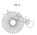
- Fig. 8 is a perspective view of a part of an outer peripheral portion of the master carrier.
- the width size of the projection 29 is larger than that of the projection 23 of the transfer pattern 21. In this way, it is possible to set up the width size of the projection 29 at an optimum width for the purposes of enhancing the adhesion and making it smooth to release the residual air.
- this master carrier 230 it is possible to perform magnetic transfer onto the slave medium 19 without causing obstacles such as deformation and damage. Moreover, it is possible to obtain good adhesion to the slave medium 19.
- Fig. 9 is a perspective view of a part of an outer peripheral portion of the master carrier.
- a projection 33 is provided concentrically along the peripheral direction of the master carrier 300 in both or either one of the inner peripheral side and the outer peripheral side of the information writing region 25.
- this master carrier 300 for the sake of performing magnetic transfer, when the master carrier 300 and the slave medium 19 are superposed, the outer peripheral side of the transfer pattern 21 is sustained by the projection 33. Accordingly, by bringing the mater carrier 300 into intimate contact with the slave medium 19, it is possible to perform magnetic transfer onto the slave medium 19 satisfactorily without causing obstacles such as deformation of the transfer pattern 21 and damage onto the surface of the slave medium 19.
- Fig. 10 is a perspective view of a part of an outer peripheral portion of the master carrier.
- a depression part 35 is provided radially in its radius direction.
- this master carrier 310 since the radial depression 35 is provided, for the sake of performing magnetic transfer, when the master carrier 310 and the slave medium 19 are superposed, air between the master carrier 310 and the slave medium 19 is introduced outside in the radius direction in the depression 35, whereby good adhesion between the master carrier 310 and the slave medium 19 can be obtained.
- this master carrier 310 it is possible to perform magnetic transfer onto the slave medium 19 without causing obstacles such as deformation and damage. Moreover, it is possible to obtain good adhesion to the slave medium 19.
- Fig. 11 is a perspective view of a part of an outer peripheral portion of the master carrier.
- a depression 37 is provided in a plural number of positions in the dispersed state against the surface of the master carrier 400 in both or either one of the inner peripheral side and the outer peripheral side of the information writing region 25.
- the surrounds of these projections 37 become a depression 39.
- this master carrier 400 for the sake of performing magnetic transfer, when the master carrier 400 and the slave medium 19 are superposed, the inner and outer peripheral sides of the transfer pattern 21 are sustained by the projections 37. Accordingly, by bringing the mater carrier 400 into intimate contact with the slave medium 19, it is possible to perform magnetic transfer onto the slave medium 19 satisfactorily without causing obstacles such as deformation of the transfer pattern 21 and damage onto the surface of the slave medium 19.
- this master carrier 400 by providing the projections 37 in a plural number of positions in the dispersed state, the surroundings of the projections 37 become the depression 39. Accordingly, for the sake of performing magnetic transfer, when the master carrier 400 and the slave medium 19 are superposed, air between the master carrier 400 and the slave medium 19 can be introduced to outside in the depression 39, whereby good adhesion between the master carrier 400 and the slave medium 19 can be obtained.
- this master carrier 400 it is possible to perform magnetic transfer onto the slave medium 19 without causing obstacles such as deformation and damage. Moreover, it is possible to obtain good adhesion to the slave medium 19.
- a gap generated by the projection 27, 29, 33 or 37 is communicated between the central side and the outer peripheral end of the master carrier 100, 200, 210, 220, 230, 300, 310 or 400.
- an alignment pitch of the projection 27, 29, 33 or 37 is set up at from 0.1 ⁇ m to 1.5 mm.
- the projection 27, 29, 33 or 37 is provided in the outer peripheral side of the information writing region 25.
- the position of the projection 27, 29, 33 or 37 is not limited to only the outer peripheral side of the information writing region 25 and is effective so far as the projection 27, 29, 33 or 37 is provided in a region other than the information writing region 25.
- Fig. 12 is a plan view to show portions suitable for providing a projection in the foregoing master carriers.
- the projection 27, 29, 33 or 37 is provided in both or either one of an outer peripheral side A of the information writing region 25 and a side portion C or D of the information writing region 25, and preferable also in an inner peripheral side B.
Landscapes
- Magnetic Record Carriers (AREA)
Claims (12)
- Urträger (100, 210, 220, 230, 300, 310, 400) zur magnetischen Übertragung, umfassend:eine Auflage (11) mit einer Informationsschreiberegion (25), wo ein Vorsprungs-Übertragungsmuster (21) mit einem ersten Vorsprung (23) ausgebildet ist; undeine magnetische Schicht (13) auf dem Übertragungsmuster der Auflage,wobei der Urträger einen zweite Vorsprung (27, 29, 33, 37) auf einer Oberfläche der Auflage aufweist, dadurchgekennzeichnet, dass
der erste Vorsprung einer auf ein magnetisches Aufnahmemedium (19) zu übertragenden Information entspricht und der zweite Vorsprung an entweder der äußeren Umfangsseite der Informationsschreiberegion oder dem Seitenabschnitt der Informationsschreiberegion oder an beiden ausgebildet ist,
wobei der erste Vorsprung und der zweite Vorsprung untereinander unterbrochen sind, wobei der zweite Vorsprung in einer Region ausgebildet ist, wo die Informationsschreiberegion nicht ausgebildet ist, um die Region, wo die Informationsschreiberegion nicht ausgebildet ist zu erhalten, während das magnetische Aufnahmemedium und die Auflage in engen Kontakt miteinander gebracht werden. - Urträger zur magnetischen Übertragung nach Anspruch 1, wobei der zweite Vorsprung eine obere Oberfläche aufweist und die obere Oberfläche im Wesentlichen eine selbe Höhe wie die des ersten Vorsprungs des Übertragungsmusters über der Oberfläche der Auflage hat.
- Urträger zur magnetischen Übertragung nach Anspruch 1, wobei der Urträger mindestens zwei Linien (29, 33) mit dem zweiten Vorsprung aufweist, wobei die Linien in einem konzentrischen Muster oder einem radialen Muster gegen die Oberfläche des Urträgers angeordnet sind und eine zweite Vertiefung (31) zwischen den Linien ausgebildet ist.
- Urträger zur magnetischen Übertragung nach Anspruch 1, wobei der Urträger mindestens zwei zweite Vorsprünge in einem verteilten Zustand gegen die Oberfläche des Urträgers aufweist.
- Urträger zur magnetischen Übertragung nach Anspruch 1, wobei ein Spalt, der durch die zweiten Vorsprünge zu einer Zeit erzeugt wird, zu der das magnetische Aufnahmemedium und die Auflage in engen Kontakt miteinander gebracht werden, zwischen einer zentralen Seite des Urträgers und einem äußeren umfangseitigen Ende des Urträgers kommuniziert wird.
- Urträger zur magnetischen Übertragung nach Anspruch 1, wobei die zweiten Vorsprünge so angeordnet sind, dass sie einen Ausrichtungsabstand von 0,1µm bis 1,5mm haben.
- Verfahren zum Herstellen eines vorformatierten magnetischen Aufnahmemediums (19), welches die folgenden Schritte umfasst:Vorbereiten eines Urträgers (100, 210, 220, 230, 300, 310, 400),Vorbereiten eines Hilfsmediums (19) mit einer nichtmagnetischen Auflage (15) mit einer magnetischen Aufnahmeschicht (17) darauf,anfängliches Magnetisieren der magnetischen Aufnahmeschicht des Hilfsmediums in eine vorbestimmte Ausrichtung,Bringen einer Oberfläche des Urmediums in einen engen Kontakt mit der magnetischen Aufnahmeschicht des Hilfsmediums unter einem vorbestimmten Druck, um einen verbundenen Körper zu bilden, undAnwenden eines magnetischen Übertragungsfelds auf den verbundenen Körper in einer der vorbestimmten Ausrichtung entgegen gesetzten Ausrichtung, dadurch Erhalten des magnetischen Aufnahmemediums mit den aufgenommenen Daten,wobei der Urträger zur magnetischen Übertragung umfasst: eine Auflage (11) mit einer Informationsschreiberegion (25), wo ein Vorsprungs-Übertragungsmuster (21) mit einem ersten Vorsprung (23) ausgebildet ist; undeine magnetische Schicht (13) auf dem Übertragungsmuster der Auflage, wobei der Urträger einen zweiten Vorsprung (27, 29, 33, 37) auf der Oberfläche der Auflage aufweist; dadurch gekennzeichnet, dassder erste Vorsprung einer auf das magnetische Aufnahmemedium zu übertragenden Information entspricht und der zweite Vorsprung entweder an der äußeren Umfangsseite der Informationsschreiberegion oder dem Seitenabschnitt der Informationsschreiberegion oder an beiden ausgebildet ist, wobei der erste Vorsprung und der zweite Vorsprung untereinander unterbrochen sind, wobei der zweite Vorsprung in einer Region ausgebildet ist, wo die Informationsschreiberegion nicht ausgebildet ist, um die Region, wo die Informationsschreiberegion nicht ausgebildet ist, zu erhalten, während das magnetische Aufnahmemedium und die Auflage in engen Kontakt miteinander gebracht werden.
- Verfahren zum Herstellen eines vorformatierten magnetischen Aufnahmemediums nach Anspruch 7, wobei der zweite Vorsprung eine obere Oberfläche aufweist und die obere Oberfläche im Wesentlichen eine selbe Höhe wie die des ersten Vorsprungs des Übertragungsmusters über der Oberfläche der Auflage hat.
- Verfahren zum Herstellen eines vorformatierten magnetischen Aufnahmemediums nach Anspruch 7 oder 8, wobei der Urträger mindestens zwei Linien mit dem zweiten Vorsprung aufweist, wobei die Linien in einem konzentrischen Muster oder einem radialen Muster gegen die Oberfläche des Urträgers angeordnet sind, und eine zweite Vertiefung zwischen den Linien ausgebildet ist.
- Verfahren zum Herstellen eines vorformatierten magnetischen Aufnahmemediums nach einem der Ansprüche 7 bis 9, wobei der Urträger mindestens zwei zweite Vorsprünge in einem verteilten Zustand gegen die Oberfläche des Urträgers aufweist.
- Verfahren zum Herstellen eines vorformatierten magnetischen Aufnahmemediums nach einem der Ansprüche 7 bis 10, wobei ein Spalt, der durch die zweiten Vorsprünge zu einer Zeit erzeugt wird, zu der das magnetische Aufnahmemedium und die Auflage in engen Kontakt miteinander gebracht werden, zwischen einer zentralen Seite des Urträgers und einem äußeren umfangseitigen Ende des Urträgers kommuniziert.
- Verfahren zum Herstellen eines vorformatierten magnetischen Aufnahmemediums nach einem der Ansprüche 7 bis 11, wobei die zweiten Vorsprünge so angeordnet sind, dass sie einen Ausrichtungsabstand von 0,1µm bis 1,5mm aufweisen.
Applications Claiming Priority (2)
| Application Number | Priority Date | Filing Date | Title |
|---|---|---|---|
| JP2003303036A JP2005071536A (ja) | 2003-08-27 | 2003-08-27 | 磁気転写用マスター担体 |
| JP2003303036 | 2003-08-27 |
Publications (3)
| Publication Number | Publication Date |
|---|---|
| EP1522993A2 EP1522993A2 (de) | 2005-04-13 |
| EP1522993A3 EP1522993A3 (de) | 2006-05-03 |
| EP1522993B1 true EP1522993B1 (de) | 2008-06-18 |
Family
ID=34308388
Family Applications (1)
| Application Number | Title | Priority Date | Filing Date |
|---|---|---|---|
| EP04020418A Expired - Lifetime EP1522993B1 (de) | 2003-08-27 | 2004-08-27 | Urträger für magnetische Übertragung |
Country Status (4)
| Country | Link |
|---|---|
| US (1) | US7630153B2 (de) |
| EP (1) | EP1522993B1 (de) |
| JP (1) | JP2005071536A (de) |
| DE (1) | DE602004014453D1 (de) |
Families Citing this family (1)
| Publication number | Priority date | Publication date | Assignee | Title |
|---|---|---|---|---|
| JP4847489B2 (ja) * | 2008-03-27 | 2011-12-28 | 富士フイルム株式会社 | 磁気転写用マスター担体及びその製造方法 |
Family Cites Families (10)
| Publication number | Priority date | Publication date | Assignee | Title |
|---|---|---|---|---|
| TW342495B (en) | 1996-07-22 | 1998-10-11 | Matsushita Electric Industrial Co Ltd | Master information carrier, method of producing the same, and method for recording master information signal on magnetic recording medium |
| JP3329259B2 (ja) | 1998-03-20 | 2002-09-30 | 松下電器産業株式会社 | マスター情報担体、および、磁気記録媒体の製造方法 |
| JPH11296849A (ja) | 1998-04-10 | 1999-10-29 | Matsushita Electric Ind Co Ltd | マスター情報担体 |
| JP3333756B2 (ja) | 1999-05-25 | 2002-10-15 | 松下電器産業株式会社 | マスター情報担体およびその製造方法 |
| JP3715152B2 (ja) | 1999-10-22 | 2005-11-09 | 松下電器産業株式会社 | マスター情報担体の製造方法 |
| US6858329B2 (en) | 2000-03-31 | 2005-02-22 | Matsushita Electric Industrial Co., Ltd. | Master disc and method for manufacturing magnetic disc using the same |
| JP3963637B2 (ja) * | 2000-09-04 | 2007-08-22 | 富士フイルム株式会社 | 磁気転写方法 |
| JP2002251721A (ja) | 2001-02-22 | 2002-09-06 | Fuji Photo Film Co Ltd | 磁気転写用マスター担体 |
| US6980380B2 (en) * | 2001-12-28 | 2005-12-27 | Matsushita Electric Industrial Co., Ltd. | Master information carrier and method for manufacturing magnetic disk |
| US7218466B1 (en) * | 2002-06-28 | 2007-05-15 | Seagate Technology Llc | Contact printing of magnetic media with mechanically reinforced and/or gas venting stamper |
-
2003
- 2003-08-27 JP JP2003303036A patent/JP2005071536A/ja active Pending
-
2004
- 2004-08-27 EP EP04020418A patent/EP1522993B1/de not_active Expired - Lifetime
- 2004-08-27 US US10/927,010 patent/US7630153B2/en not_active Expired - Fee Related
- 2004-08-27 DE DE602004014453T patent/DE602004014453D1/de not_active Expired - Lifetime
Also Published As
| Publication number | Publication date |
|---|---|
| EP1522993A3 (de) | 2006-05-03 |
| US20050078392A1 (en) | 2005-04-14 |
| DE602004014453D1 (de) | 2008-07-31 |
| US7630153B2 (en) | 2009-12-08 |
| JP2005071536A (ja) | 2005-03-17 |
| EP1522993A2 (de) | 2005-04-13 |
Similar Documents
| Publication | Publication Date | Title |
|---|---|---|
| KR20020086291A (ko) | 자기전사용 마스터담체 | |
| KR20020088375A (ko) | 자기전사용 마스터담체 및 자기전사방법, 그리고자기전사용 마스터담체의 제작방법 | |
| KR20020018946A (ko) | 자기전사방법 | |
| EP1420399B1 (de) | Verfahren zum Schreiben eines Servosignalmusters für Magnetplatten mittels Elektronenstrahl | |
| EP1522993B1 (de) | Urträger für magnetische Übertragung | |
| KR20020062593A (ko) | 자기전사용 마스터담체 | |
| JP4118989B2 (ja) | 磁気転写装置 | |
| KR20030051281A (ko) | 자기전사용 마스터 담체 | |
| EP1580732B1 (de) | Magnetisches Auzeichnungsmedium, Verfahren zur Herstellung des magnetischen Auzeichnungsmediums, gemusterte Informationsträgermatrize für magnetische Übertragung, die während der Herstellung des magnetischen Aufzeichnungsmediums verwendet wird und magnetisches Aufzeichnungs/wiedergabegerät | |
| JP2003272142A (ja) | 磁気転写用マスター担体 | |
| US7139140B2 (en) | Method and apparatus of magnetically transferring information signal from master medium to slave medium | |
| US20040201912A1 (en) | Magnetic transfer master carrier | |
| US7368186B2 (en) | Master carrier for magnetic transfer | |
| KR20020088366A (ko) | 자기전사방법 및 자기전사장치 | |
| JP2008010028A (ja) | 垂直磁気記録媒体の磁気転写方法、垂直磁気記録媒体及び磁気記録装置 | |
| EP1691351A2 (de) | Plattenförmiges magnetisches Aufzeichnungsmedium | |
| US20050024757A1 (en) | Master carrier for magnetic transfer | |
| US20050277000A1 (en) | Process for producing magnetic recording medium with limited coercivity squareness ratio | |
| JP2007242165A (ja) | 垂直磁気転写用マスター媒体、垂直磁気転写方法、垂直磁気記録媒体、及び垂直磁気記録装置 | |
| JP2011090738A (ja) | 磁気転写用パターンの描画方法 | |
| JP2001273632A (ja) | 磁気転写方法 | |
| JP2004241023A (ja) | 磁気転写用マスター担体 | |
| JP2003016744A (ja) | 磁気記録媒体 | |
| JP2002216343A (ja) | 磁気転写用マスター担体 | |
| JP2003217115A (ja) | 磁気転写用磁気記録媒体 |
Legal Events
| Date | Code | Title | Description |
|---|---|---|---|
| PUAI | Public reference made under article 153(3) epc to a published international application that has entered the european phase |
Free format text: ORIGINAL CODE: 0009012 |
|
| AK | Designated contracting states |
Kind code of ref document: A2 Designated state(s): AT BE BG CH CY CZ DE DK EE ES FI FR GB GR HU IE IT LI LU MC NL PL PT RO SE SI SK TR |
|
| AX | Request for extension of the european patent |
Extension state: AL HR LT LV MK |
|
| PUAL | Search report despatched |
Free format text: ORIGINAL CODE: 0009013 |
|
| AK | Designated contracting states |
Kind code of ref document: A3 Designated state(s): AT BE BG CH CY CZ DE DK EE ES FI FR GB GR HU IE IT LI LU MC NL PL PT RO SE SI SK TR |
|
| AX | Request for extension of the european patent |
Extension state: AL HR LT LV MK |
|
| 17P | Request for examination filed |
Effective date: 20060907 |
|
| 17Q | First examination report despatched |
Effective date: 20061004 |
|
| AKX | Designation fees paid |
Designated state(s): DE FR GB |
|
| RAP1 | Party data changed (applicant data changed or rights of an application transferred) |
Owner name: FUJIFILM CORPORATION |
|
| 17Q | First examination report despatched |
Effective date: 20061004 |
|
| GRAP | Despatch of communication of intention to grant a patent |
Free format text: ORIGINAL CODE: EPIDOSNIGR1 |
|
| GRAS | Grant fee paid |
Free format text: ORIGINAL CODE: EPIDOSNIGR3 |
|
| GRAA | (expected) grant |
Free format text: ORIGINAL CODE: 0009210 |
|
| AK | Designated contracting states |
Kind code of ref document: B1 Designated state(s): DE FR GB |
|
| REG | Reference to a national code |
Ref country code: GB Ref legal event code: FG4D |
|
| REF | Corresponds to: |
Ref document number: 602004014453 Country of ref document: DE Date of ref document: 20080731 Kind code of ref document: P |
|
| PLBE | No opposition filed within time limit |
Free format text: ORIGINAL CODE: 0009261 |
|
| STAA | Information on the status of an ep patent application or granted ep patent |
Free format text: STATUS: NO OPPOSITION FILED WITHIN TIME LIMIT |
|
| 26N | No opposition filed |
Effective date: 20090319 |
|
| PGFP | Annual fee paid to national office [announced via postgrant information from national office to epo] |
Ref country code: GB Payment date: 20120822 Year of fee payment: 9 |
|
| PGFP | Annual fee paid to national office [announced via postgrant information from national office to epo] |
Ref country code: FR Payment date: 20120823 Year of fee payment: 9 Ref country code: DE Payment date: 20120822 Year of fee payment: 9 |
|
| GBPC | Gb: european patent ceased through non-payment of renewal fee |
Effective date: 20130827 |
|
| PG25 | Lapsed in a contracting state [announced via postgrant information from national office to epo] |
Ref country code: DE Free format text: LAPSE BECAUSE OF NON-PAYMENT OF DUE FEES Effective date: 20140301 |
|
| REG | Reference to a national code |
Ref country code: DE Ref legal event code: R119 Ref document number: 602004014453 Country of ref document: DE Effective date: 20140301 |
|
| REG | Reference to a national code |
Ref country code: FR Ref legal event code: ST Effective date: 20140430 |
|
| PG25 | Lapsed in a contracting state [announced via postgrant information from national office to epo] |
Ref country code: GB Free format text: LAPSE BECAUSE OF NON-PAYMENT OF DUE FEES Effective date: 20130827 |
|
| PG25 | Lapsed in a contracting state [announced via postgrant information from national office to epo] |
Ref country code: FR Free format text: LAPSE BECAUSE OF NON-PAYMENT OF DUE FEES Effective date: 20130902 |