EP1522810A2 - Wärmeübertrager für ein Kraftfahrzeug, insbesondere Kühlmittel/Luft-Kühler - Google Patents
Wärmeübertrager für ein Kraftfahrzeug, insbesondere Kühlmittel/Luft-Kühler Download PDFInfo
- Publication number
- EP1522810A2 EP1522810A2 EP20040021520 EP04021520A EP1522810A2 EP 1522810 A2 EP1522810 A2 EP 1522810A2 EP 20040021520 EP20040021520 EP 20040021520 EP 04021520 A EP04021520 A EP 04021520A EP 1522810 A2 EP1522810 A2 EP 1522810A2
- Authority
- EP
- European Patent Office
- Prior art keywords
- heat exchanger
- exchanger according
- coolant
- fastening elements
- leg
- Prior art date
- Legal status (The legal status is an assumption and is not a legal conclusion. Google has not performed a legal analysis and makes no representation as to the accuracy of the status listed.)
- Withdrawn
Links
- 239000002826 coolant Substances 0.000 title claims abstract description 30
- 238000001816 cooling Methods 0.000 claims description 31
- 238000002347 injection Methods 0.000 claims description 7
- 239000007924 injection Substances 0.000 claims description 7
- 239000003507 refrigerant Substances 0.000 claims description 7
- 239000003351 stiffener Substances 0.000 claims 1
- 238000001746 injection moulding Methods 0.000 abstract 1
- 239000003570 air Substances 0.000 description 23
- 238000009434 installation Methods 0.000 description 4
- 238000004519 manufacturing process Methods 0.000 description 3
- 238000004378 air conditioning Methods 0.000 description 1
- 239000012080 ambient air Substances 0.000 description 1
- 238000005452 bending Methods 0.000 description 1
- 230000002035 prolonged effect Effects 0.000 description 1
- 238000004904 shortening Methods 0.000 description 1
- 238000005507 spraying Methods 0.000 description 1
Images

Classifications
-
- F—MECHANICAL ENGINEERING; LIGHTING; HEATING; WEAPONS; BLASTING
- F28—HEAT EXCHANGE IN GENERAL
- F28D—HEAT-EXCHANGE APPARATUS, NOT PROVIDED FOR IN ANOTHER SUBCLASS, IN WHICH THE HEAT-EXCHANGE MEDIA DO NOT COME INTO DIRECT CONTACT
- F28D1/00—Heat-exchange apparatus having stationary conduit assemblies for one heat-exchange medium only, the media being in contact with different sides of the conduit wall, in which the other heat-exchange medium is a large body of fluid, e.g. domestic or motor car radiators
- F28D1/02—Heat-exchange apparatus having stationary conduit assemblies for one heat-exchange medium only, the media being in contact with different sides of the conduit wall, in which the other heat-exchange medium is a large body of fluid, e.g. domestic or motor car radiators with heat-exchange conduits immersed in the body of fluid
- F28D1/04—Heat-exchange apparatus having stationary conduit assemblies for one heat-exchange medium only, the media being in contact with different sides of the conduit wall, in which the other heat-exchange medium is a large body of fluid, e.g. domestic or motor car radiators with heat-exchange conduits immersed in the body of fluid with tubular conduits
- F28D1/0408—Multi-circuit heat exchangers, e.g. integrating different heat exchange sections in the same unit or heat exchangers for more than two fluids
- F28D1/0426—Multi-circuit heat exchangers, e.g. integrating different heat exchange sections in the same unit or heat exchangers for more than two fluids with units having particular arrangement relative to the large body of fluid, e.g. with interleaved units or with adjacent heat exchange units in common air flow or with units extending at an angle to each other or with units arranged around a central element
- F28D1/0435—Combination of units extending one behind the other
-
- B—PERFORMING OPERATIONS; TRANSPORTING
- B29—WORKING OF PLASTICS; WORKING OF SUBSTANCES IN A PLASTIC STATE IN GENERAL
- B29C—SHAPING OR JOINING OF PLASTICS; SHAPING OF MATERIAL IN A PLASTIC STATE, NOT OTHERWISE PROVIDED FOR; AFTER-TREATMENT OF THE SHAPED PRODUCTS, e.g. REPAIRING
- B29C33/00—Moulds or cores; Details thereof or accessories therefor
- B29C33/30—Mounting, exchanging or centering
- B29C33/306—Exchangeable mould parts, e.g. cassette moulds, mould inserts
-
- F—MECHANICAL ENGINEERING; LIGHTING; HEATING; WEAPONS; BLASTING
- F28—HEAT EXCHANGE IN GENERAL
- F28F—DETAILS OF HEAT-EXCHANGE AND HEAT-TRANSFER APPARATUS, OF GENERAL APPLICATION
- F28F9/00—Casings; Header boxes; Auxiliary supports for elements; Auxiliary members within casings
- F28F9/001—Casings in the form of plate-like arrangements; Frames enclosing a heat exchange core
- F28F9/002—Casings in the form of plate-like arrangements; Frames enclosing a heat exchange core with fastening means for other structures
-
- F—MECHANICAL ENGINEERING; LIGHTING; HEATING; WEAPONS; BLASTING
- F28—HEAT EXCHANGE IN GENERAL
- F28F—DETAILS OF HEAT-EXCHANGE AND HEAT-TRANSFER APPARATUS, OF GENERAL APPLICATION
- F28F2255/00—Heat exchanger elements made of materials having special features or resulting from particular manufacturing processes
- F28F2255/14—Heat exchanger elements made of materials having special features or resulting from particular manufacturing processes molded
- F28F2255/143—Heat exchanger elements made of materials having special features or resulting from particular manufacturing processes molded injection molded
Definitions
- the invention relates to a heat exchanger for a motor vehicle, in particular a coolant / air cooler according to the preamble of claim 1.
- Heat exchangers for motor vehicles such as coolant / air cooler, charge air / air cooler, Refrigerant / air condensers and / or oil / air coolers are usually arranged in the front engine compartment of the motor vehicle, wherein said heat exchanger often to a pre-assembled Cooling module are summarized.
- Such cooling module consisting of a coolant / air cooler, a Charge air / air cooler and a refrigerant / air condenser known.
- the Heat exchangers are firmly interconnected to form a structural unit, which is inserted into the vehicle and fastened there. For the attachment has one of the heat exchanger fastening elements z. B.
- the different Fastening elements through the use of so-called exchangeable inserts produced on the injection mold.
- the injection mold for spraying of the collecting tank comes with different interchangeable inserts, the especially to the different dimensions and positions of the fasteners are fitted, equipped so that the rest of the tool the same remains.
- the fasteners formed as a holder with an L-profile, with a (vertical) L-leg is integrated into the wall of the collecting tank and the other (horizontal) L-leg protrudes from the collection box and a foot for the Attachment of the heat exchanger forms.
- This foot has different Lengths, depending on installation requirements in the vehicle. This will be the Advantage achieved that the heat exchanger -. B. in the direction of travel Vehicle seen - in different positions, eg. B. 5 cm further fastened at the front with the same vehicle-fixed attachment points can.
- the L-legs stiffened by ribs, so that in cross section a U-profile with increased Resistance moment results.
- the ribbed L-profile is suitable in particular for receiving bending stresses, which in the prolonged foot increasingly occur.
- the upper fastening elements formed at the collecting boxes as open box sections, which can be sprayed on at different positions of the collecting tank are, for. B. on the front and on the back. This happens as well by replacing the inserts in the injection mold.
- upper fasteners is the heat exchanger or the cooling module attached to the upper cross member of the vehicle by there vehicle-mounted Engage mounting pins in the box profiles.
- the heat exchanger is used with the fasteners as a carrier for other heat exchangers such as B. a charge air cooler and / or a refrigerant condenser, as seen in the direction of air flow, in front of or behind the heat exchanger, which is formed in this case as a coolant air cooler, arranged are.
- the coolant air cooler is used with the fastening elements according to the invention as a carrier for the entire cooling module.
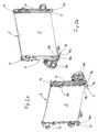
- Fig. 1, 1a, 1b and 1 show in different views, a cooling module 1, which is composed of a coolant radiator 2, a charge air cooler 3 and arranged between the two refrigerant condenser 4.
- the heat exchangers 2, 3, 4 are mechanically connected to each other in an unspecified manner here to form an assembly, the cooling module 1.
- the coolant cooler 2, which acts as a carrier for the entire cooling module 1, has a network (block) 5 soldered from flat tubes and corrugated ribs, not shown, and two laterally arranged collecting boxes 6, 7 made of plastic, each of which is mechanically connected to a metallic tubesheet 8, 9 are connected.
- the coolant radiator 2 is designed as a so-called cross-flow radiator, ie installed with horizontal pipes and vertical collecting tanks 6, 7 in the vehicle, not shown.
- the collecting tanks 6, 7 each have a coolant outlet nozzle 6a and a coolant inlet nozzle 7a, via which the connection to a coolant circuit (not shown) takes place.
- the intercooler 3, the charge air pipe 3a, 3b has, connected to an unillustrated charge air system and the refrigerant condenser 4 via a connecting flange 4a with a refrigerant circuit, not shown, of a vehicle air conditioning.
- the cooling module 1 is flowed through by ambient air in the direction of the arrows L.
- the support of the cooling module 1 via lower fasteners 10, 11 and upper fastening elements 12, 13 (FIG. 1 a), which in each case the coolant boxes 6, 7 are molded, d. H. integral with these in Plastic are formed.
- the lower fastening elements 10, 11 are designed as L-profiles and have on their underside each have a mounting pin 10a, 11a, by means of which the cooling module 1 in not shown elastic receiving bushes on a cross member, not shown of the vehicle is fixed.
- the distance, seen in the direction of travel, between the mounting pins 10a, 11a and the end face of the radiator network 5 is indicated by L1.
- the upper fastening elements 12, 13 are formed as open box sections, which on an unillustrated upper lock cross member of the vehicle are held.
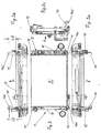
- Fig. 2a and 2b show two different perspective views of the coolant radiator 2 of FIG. 1, seen in the direction of travel, ie in the direction of the air outlet side of the network 5 and the open sides of the coolant pipe 6a, 7a and the charge air nozzle 3a, 3b.
- the fastening element 11 is molded in the form of an L-profile, ie in the form of a horizontally projecting foot which is stiffened by two lateral ribs 11 b, 11 c.
- the fastening element 10 likewise molded in the form of an L-profile, is injection-molded on the coolant box 7, wherein a horizontally protruding foot with stiffening ribs 10b, 10c can also be seen here.
- the fastening pins 10a, 11a are injection-molded, which serve to receive horizontal thrust forces.
- the upwardly open box section 12, 13 are arranged.
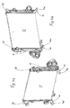
- FIG. 3a, 3b and 3c show different views, namely from the front, from above, from below and from the side of a second type of cooling module 1 ', which differs from the previously described cooling module 1 only by the dimensions and the positions of Fasteners 10 ', 11' 12 ', 13' different.
- this cooling module 1 ' corresponds in terms of number, size and design of the heat exchanger, the cooling module 1.
- L2 the distance of the mounting pins 10a', 11a 'of the end face 5' of the coolant radiator 2 denoted by L2.
- L2 is considerably larger than L1.
- the ratio L2 / L1 which results here from the graphic representation, however, is arbitrary and can vary up or down, z. B. by lengthening or shortening of the foot 10 ', 11'.
- the further views Fig. 3a and Fig. 3c also show the enlarged dimension L2 compared to the first embodiment of the cooling module 1.
- the upper attachment points are offset, ie the fasteners 12 ', 13' are located in the cooling module 1 'and at the coolant cooler 2 'on the back of the coolant boxes 6', 7 ', ie on the side of the air outlet surface 5'.
- the direction of flow of the air through the cooling module 1 ' is indicated by arrows L (the direction of travel, not shown, of the motor vehicle is the opposite direction).
- FIGS. 4a and 4b show two different perspective views of the coolant cooler 2 'with a view of its air outlet-side end face 5'.
- the perspective representation shows the different lengths of the feet or fastening elements 10 ', 11' in comparison to FIGS. 2a and 2b.
- the different positions of the upper fastening elements 12 'and 13' which are arranged here on the back of the coolant boxes 6 ', 7'. They are offset from the first type of cooling module 1 by approximately the same amount in the direction of air flow as the fastening pins 10a ', 11a'.
- the change in the dimensions of the lower fasteners of L1 to L2 and the change in the positions of the upper fasteners 12 ', 13' from the front to the back causes the installation of the cooling module that the cooling module 1 'by the difference L2 - L1 in the direction of travel in the vehicle moves forward - as already mentioned, at the same Attachment points in the vehicle, d. H. in the lower and upper cross member.
Landscapes
- Engineering & Computer Science (AREA)
- Mechanical Engineering (AREA)
- Physics & Mathematics (AREA)
- Thermal Sciences (AREA)
- General Engineering & Computer Science (AREA)
- Cooling, Air Intake And Gas Exhaust, And Fuel Tank Arrangements In Propulsion Units (AREA)
- Air-Conditioning For Vehicles (AREA)
Abstract
Description
- Fig. 1, 1a, 1b, 1c
- einen ersten Typ von Kühlmodul in einer Ansicht, einer Draufsicht, einer Ansicht von unten und einer Seitenansicht,
- Fig. 2a, 2b
- einen Kühlmittelkühler des Kühlmoduls in zwei verschiedenen perspektivischen Darstellungen mit Befestigungselementen,
- Fig. 3, 3a, 3b, 3c
- einen zweiten Typ von Kühlmodul mit veränderten Befestigungselementen in einer Ansicht, einer Draufsicht, einer Ansicht von unten und einer Seitenansicht und
- Fig. 4a, 4b
- den Kühlmittelkühler des Kühlmoduls gemäß Fig. 3 in zwei unterschiedlichen perspektivischen Darstellungen mit veränderten Befestigungselementen.
Claims (10)
- Wärmeübertrager für ein Kraftfahrzeug, insbesondere Kühlmittel/Luft-Kühler (2, 2'), welcher im Kraftfahrzeug an einem unteren Träger und einem oberen Querträger mittels oberen und unteren Befestigungselementen befestigbar ist, wobei der Wärmeübertrager (2, 2') Sammelkästen (6, 7, 6', 7') aus Kunststoff aufweist, an welche die Befestigungselemente anspritzbar sind, dadurch gekennzeichnet, dass die Befestigungselemente (10, 11, 12, 13; 10', 11', 12' 13') mit unterschiedlichen Positionen und/oder unterschiedlichen Abmessungen, insbesondere zwei Positionen und/oder zwei Abmessungen (L1, L2) herstellbar sind.
- Wärmeübertrager nach Anspruch 1, dadurch gekennzeichnet, dass die Sammelkästen (6, 6', 7, 7') in einem Spritzwerkzeug mit Wechseleinsätzen abspritzbar sind und dass die Befestigungselemente (10, 11, 12, 13; 10', 11', 12', 13') durch einen Austausch der Wechseleinsätze herstellbar sind.
- Wärmeübertrager nach Anspruch 1 oder 2, dadurch gekennzeichnet, dass die unteren Befestigungselemente (10, 11; 10', 11') als Halter mit einem L-Profil ausgebildet sind.
- Wärmeübertrager nach Anspruch 3, dadurch gekennzeichnet, dass ein L-Schenkel vom Sammelkasten (6, 7; 6', 7') abragt und der andere L-Schenkel in den Sammelkasten übergeht und dass der abragende L-Schenkel unterschiedliche Längen (L1, L2) aufweist.
- Wärmeübertrager nach Anspruch 4, dadurch gekennzeichnet, dass der abragende L-Schenkel (10, 11; 10', 11') durch Rippen (10b, 10c, 11 b, 11 c) versteift ist, die ein U-Profil bilden.
- Wärmeübertrager nach Anspruch 3, 4 oder5, dadurch gekennzeichnet, dass am dem Sammelkasten (6, 7; 6', 7') abgewandten Ende des abragenden Schenkels (10, 11; 10', 11') ein Haltezapfen (10a, 11 a; 10'a, 11'a) angeordnet ist.
- Wärmeübertrager nach Anspruch 7, dadurch gekennzeichnet, dass die oberen Befestigungselemente (12, 13; 12', 13') wechselweise auf unterschiedlichen Positionen des Sammelkastens (6, 7; 6', 7') angeordnet sind, insbesondere auf sich gegenüber liegenden Längsseiten der Sammelkästen.
- Wärmeübertrager nach einem der Ansprüche 1 bis 8, dadurch gekennzeichnet, dass die Sammelkästen (6, 7) jeweils mit Rohrböden (8, 9) verbunden sind, zwischen denen ein Rohr/Rippen-Block (5) angeordnet ist.
- Wärmeübertrager nach einem der Ansprüche 1 bis 9, dadurch gekennzeichnet, dass an dem Wärmeübertrager (2) weitere ein Kühlmodul (1) bildende Wärmeübertrager, insbesondere ein Ladeluft/Luft-Kühler (3) und/oder ein Kältemittel/Luft-Kondensator (4) befestigt sind.
- Wärmeübertrager nach einem der Ansprüche 1 bis 10, dadurch gekennzeichnet, dass der Wärmeübertrager, insbesondere der Kühlmittelkühler (2) als Querstrom-Wärmeübertrager mit seitlich und senkrecht angeordneten Sammelkästen (6, 7) ausgebildet ist.
Applications Claiming Priority (2)
| Application Number | Priority Date | Filing Date | Title |
|---|---|---|---|
| DE10347679A DE10347679A1 (de) | 2003-10-09 | 2003-10-09 | Wärmeübertrager für ein Kraftfahrzeug, insbesondere Kühlmittel/Luft-Kühler |
| DE10347679 | 2003-10-09 |
Publications (2)
| Publication Number | Publication Date |
|---|---|
| EP1522810A2 true EP1522810A2 (de) | 2005-04-13 |
| EP1522810A3 EP1522810A3 (de) | 2013-03-27 |
Family
ID=34306394
Family Applications (1)
| Application Number | Title | Priority Date | Filing Date |
|---|---|---|---|
| EP20040021520 Withdrawn EP1522810A3 (de) | 2003-10-09 | 2004-09-10 | Wärmeübertrager für ein Kraftfahrzeug, insbesondere Kühlmittel/Luft-Kühler |
Country Status (3)
| Country | Link |
|---|---|
| US (1) | US7172014B2 (de) |
| EP (1) | EP1522810A3 (de) |
| DE (1) | DE10347679A1 (de) |
Cited By (1)
| Publication number | Priority date | Publication date | Assignee | Title |
|---|---|---|---|---|
| LU102213B1 (en) * | 2020-11-18 | 2022-05-18 | Estra Automotive Systems Luxembourg S A R L | Cooling module for an internal combustion engine |
Families Citing this family (5)
| Publication number | Priority date | Publication date | Assignee | Title |
|---|---|---|---|---|
| FR2871739B1 (fr) * | 2004-06-21 | 2006-09-15 | Valeo Climatisation Sa | Boitier a couvercle d'etancheite externe et de calage, pour une installation de chauffage, ventilation et/ou climatisation d'habitacle |
| US7165537B2 (en) * | 2004-11-10 | 2007-01-23 | Honeywell International Inc. | Charge air cooler |
| DE102005008103A1 (de) * | 2005-02-21 | 2006-08-31 | Behr Gmbh & Co. Kg | Abgasturboladerbrennkraftmaschine |
| US9890692B1 (en) * | 2017-06-22 | 2018-02-13 | Brett Turnage | Modular intercooler system |
| US11320215B2 (en) | 2019-06-24 | 2022-05-03 | Denso International America, Inc. | Radiator including thermal stress countermeasure |
Citations (3)
| Publication number | Priority date | Publication date | Assignee | Title |
|---|---|---|---|---|
| DE19744173A1 (de) * | 1997-10-07 | 1999-04-08 | Opel Adam Ag | Elastische Abstützung eines Wärmetauschers für eine Brennkraftmaschine insbesondere in einem Kraftfahrzeug |
| DE19953787A1 (de) | 1999-11-09 | 2001-05-10 | Behr Gmbh & Co | Anordnung zur gegenseitigen Verbindung von zwei Wärmeübertragern |
| JP2002219951A (ja) * | 2001-01-25 | 2002-08-06 | Denso Corp | 車両用ラジエータの取付け構造 |
Family Cites Families (13)
| Publication number | Priority date | Publication date | Assignee | Title |
|---|---|---|---|---|
| US4940086A (en) * | 1987-04-16 | 1990-07-10 | Modine Manufacturing Company | Tank for a heat exchanger |
| DE9002438U1 (de) * | 1990-03-02 | 1990-04-12 | Süddeutsche Kühlerfabrik Julius Fr. Behr GmbH & Co KG, 7000 Stuttgart | Kunststoffwasserkasten für Wärmetauscher |
| US5160474A (en) * | 1990-12-21 | 1992-11-03 | Cadillac Rubber & Plastics, Inc. | Overmolded gasket, heat exchanger tank incorporating the same and method for making the same |
| DE4244037C2 (de) * | 1992-12-24 | 1995-10-05 | Behr Gmbh & Co | Kühlaggregat für einen Verbrennungsmotor |
| DE4244039C2 (de) * | 1992-12-24 | 1996-07-11 | Behr Gmbh & Co | Kühlmodul für Verbrennungskraftmaschinen |
| JP2612430B2 (ja) * | 1995-01-30 | 1997-05-21 | カルソニック株式会社 | ラジエータの取付及びラジエータの樹脂製下部タンク及びその製造方法並びにその製造用金型 |
| IT1310742B1 (it) * | 1999-11-26 | 2002-02-22 | Magneti Marelli Climat Srl | Gruppo di scambio termico per veicoli. |
| IT1321055B1 (it) * | 2000-11-10 | 2003-12-30 | Magneti Marelli Climat Srl | Radiatore per veicoli con perno di fissaggio sostituibile. |
| CA2448736C (en) * | 2001-06-05 | 2010-08-10 | Mikro Systems, Inc. | Methods for manufacturing three-dimensional devices and devices created thereby |
| DE10158436A1 (de) | 2001-11-29 | 2003-06-12 | Behr Gmbh & Co | Wärmetauscher |
| EP1319579B1 (de) * | 2001-12-07 | 2003-10-08 | DENSO THERMAL SYSTEMS S.p.A. | Vorassembliertes Frontmodul für Kraftfahrzeuge |
| DE10203521A1 (de) * | 2002-01-30 | 2003-07-31 | Modine Mfg Co | Schnellverschlusskupplung |
| DE10251777A1 (de) | 2002-11-05 | 2004-05-19 | Behr Gmbh & Co. | Sammelbehälter, Wärmetauscher und Kältemittelkreislauf |
-
2003
- 2003-10-09 DE DE10347679A patent/DE10347679A1/de not_active Withdrawn
-
2004
- 2004-09-10 EP EP20040021520 patent/EP1522810A3/de not_active Withdrawn
- 2004-10-07 US US10/959,951 patent/US7172014B2/en not_active Expired - Lifetime
Patent Citations (3)
| Publication number | Priority date | Publication date | Assignee | Title |
|---|---|---|---|---|
| DE19744173A1 (de) * | 1997-10-07 | 1999-04-08 | Opel Adam Ag | Elastische Abstützung eines Wärmetauschers für eine Brennkraftmaschine insbesondere in einem Kraftfahrzeug |
| DE19953787A1 (de) | 1999-11-09 | 2001-05-10 | Behr Gmbh & Co | Anordnung zur gegenseitigen Verbindung von zwei Wärmeübertragern |
| JP2002219951A (ja) * | 2001-01-25 | 2002-08-06 | Denso Corp | 車両用ラジエータの取付け構造 |
Cited By (1)
| Publication number | Priority date | Publication date | Assignee | Title |
|---|---|---|---|---|
| LU102213B1 (en) * | 2020-11-18 | 2022-05-18 | Estra Automotive Systems Luxembourg S A R L | Cooling module for an internal combustion engine |
Also Published As
| Publication number | Publication date |
|---|---|
| US20050092470A1 (en) | 2005-05-05 |
| DE10347679A1 (de) | 2005-05-04 |
| US7172014B2 (en) | 2007-02-06 |
| EP1522810A3 (de) | 2013-03-27 |
Similar Documents
| Publication | Publication Date | Title |
|---|---|---|
| DE4142023C2 (de) | Wärmetauschereinheit für Kraftfahrzeuge | |
| EP2044304B1 (de) | Wärmetauscher mit kupplungsanschluss, beispielsweise ladeluftkühler, und kupplungsanschluss für wärmetauscher | |
| DE102004058724B4 (de) | Wärmetauscher und Kühlmodul mit diesem | |
| DE69916015T2 (de) | Wärmeaustauschmodul mit lüfterhaube und wärmetauscher insbesondere für kraftfahrzeug | |
| DE3720483A1 (de) | Waermetauscher | |
| EP1724536B1 (de) | Wärmetauscher mit Akkumulator | |
| EP0864840B1 (de) | Wärmeübertrager für ein Kraftfahrzeug | |
| EP1714098B1 (de) | Anordnung zweier wärmeübertrager | |
| EP1676087A1 (de) | Kuhlmittelkuhler eines kraftfahrzeuges | |
| EP1676085B1 (de) | Wärmeübertrageranordnung | |
| EP1678456B1 (de) | Wärmeübertragermodul für ein kraftfahrzeug | |
| DE2558895A1 (de) | Waermetauscher, insbesondere kuehler, fuer fahrzeuge | |
| DE102005043937B4 (de) | Befestigungs- und Verbindungselement für Wärmeübertrager und Anordnung von Wärmeübertragern in einem Kraftfahrzeug | |
| EP1522810A2 (de) | Wärmeübertrager für ein Kraftfahrzeug, insbesondere Kühlmittel/Luft-Kühler | |
| EP1685357A1 (de) | Anordnung zur befestigung einer lüfterzarge | |
| DE69317086T2 (de) | Fahrzeugkühler | |
| DE19953785B4 (de) | Kühlermodul | |
| DE102007006241A1 (de) | Befestigungsanordnung für Wärmeübertrager | |
| DE102004024151A1 (de) | Frontende-Aufbau eines Fahrzeugs | |
| DE102023129755A1 (de) | Wärmeübertrageranordnung und Kraftfahrzeug | |
| DE202009011439U1 (de) | Anordnung zur Befestigung eines ersten Wärmeübertragers an einem zweiten Wärmeübertrager | |
| DE102004049670B4 (de) | Kraftstoffkühler, Kraftfahrzeug mit einem derartigen Kraftstoffkühler | |
| EP1650521A2 (de) | Anordnung zur gegenseitigen Befestigung von Wärmeübertragern, insbesondere in einem Kraftfahrzeug | |
| EP1816426B1 (de) | Wärmeübertrageranordnung, insbesondere eines Heckverdampfers in einem Kraftfahrzeug | |
| DE102021101772A1 (de) | Wärmetauscher mit Dichtleiste |
Legal Events
| Date | Code | Title | Description |
|---|---|---|---|
| PUAI | Public reference made under article 153(3) epc to a published international application that has entered the european phase |
Free format text: ORIGINAL CODE: 0009012 |
|
| AK | Designated contracting states |
Kind code of ref document: A2 Designated state(s): AT BE BG CH CY CZ DE DK EE ES FI FR GB GR HU IE IT LI LU MC NL PL PT RO SE SI SK TR |
|
| AX | Request for extension of the european patent |
Extension state: AL HR LT LV MK |
|
| PUAL | Search report despatched |
Free format text: ORIGINAL CODE: 0009013 |
|
| AK | Designated contracting states |
Kind code of ref document: A3 Designated state(s): AT BE BG CH CY CZ DE DK EE ES FI FR GB GR HU IE IT LI LU MC NL PL PT RO SE SI SK TR |
|
| AX | Request for extension of the european patent |
Extension state: AL HR LT LV MK |
|
| RIC1 | Information provided on ipc code assigned before grant |
Ipc: F28F 9/00 20060101ALI20130215BHEP Ipc: F28D 1/04 20060101AFI20130215BHEP |
|
| 17P | Request for examination filed |
Effective date: 20130927 |
|
| RBV | Designated contracting states (corrected) |
Designated state(s): AT BE BG CH CY CZ DE DK EE ES FI FR GB GR HU IE IT LI LU MC NL PL PT RO SE SI SK TR |
|
| AKX | Designation fees paid |
Designated state(s): DE FR |
|
| RAP1 | Party data changed (applicant data changed or rights of an application transferred) |
Owner name: MAHLE BEHR GMBH & CO. KG |
|
| 17Q | First examination report despatched |
Effective date: 20150327 |
|
| RIC1 | Information provided on ipc code assigned before grant |
Ipc: F28D 1/04 20060101ALI20190327BHEP Ipc: B29C 33/30 20060101AFI20190327BHEP Ipc: F28F 9/00 20060101ALI20190327BHEP |
|
| GRAP | Despatch of communication of intention to grant a patent |
Free format text: ORIGINAL CODE: EPIDOSNIGR1 |
|
| INTG | Intention to grant announced |
Effective date: 20190514 |
|
| STAA | Information on the status of an ep patent application or granted ep patent |
Free format text: STATUS: THE APPLICATION IS DEEMED TO BE WITHDRAWN |
|
| 18D | Application deemed to be withdrawn |
Effective date: 20190925 |