EP1522656B1 - Poignée de porte ou de couvercle d'un véhicule - Google Patents
Poignée de porte ou de couvercle d'un véhicule Download PDFInfo
- Publication number
- EP1522656B1 EP1522656B1 EP04023639A EP04023639A EP1522656B1 EP 1522656 B1 EP1522656 B1 EP 1522656B1 EP 04023639 A EP04023639 A EP 04023639A EP 04023639 A EP04023639 A EP 04023639A EP 1522656 B1 EP1522656 B1 EP 1522656B1
- Authority
- EP
- European Patent Office
- Prior art keywords
- tower
- handle according
- carrier
- arm
- locking
- Prior art date
- Legal status (The legal status is an assumption and is not a legal conclusion. Google has not performed a legal analysis and makes no representation as to the accuracy of the status listed.)
- Expired - Lifetime
Links
- 238000003780 insertion Methods 0.000 claims abstract description 17
- 230000037431 insertion Effects 0.000 claims abstract description 17
- 230000003014 reinforcing effect Effects 0.000 claims description 23
- 229920003023 plastic Polymers 0.000 claims description 2
- 239000004033 plastic Substances 0.000 claims description 2
- 238000010276 construction Methods 0.000 claims 1
- 230000000903 blocking effect Effects 0.000 description 8
- 230000004888 barrier function Effects 0.000 description 3
- 230000007704 transition Effects 0.000 description 2
- 238000004804 winding Methods 0.000 description 2
- 230000008878 coupling Effects 0.000 description 1
- 238000010168 coupling process Methods 0.000 description 1
- 238000005859 coupling reaction Methods 0.000 description 1
- 230000001419 dependent effect Effects 0.000 description 1
- 238000000605 extraction Methods 0.000 description 1
- 238000009434 installation Methods 0.000 description 1
- 239000007769 metal material Substances 0.000 description 1
- 230000002787 reinforcement Effects 0.000 description 1
Images



Classifications
-
- E—FIXED CONSTRUCTIONS
- E05—LOCKS; KEYS; WINDOW OR DOOR FITTINGS; SAFES
- E05B—LOCKS; ACCESSORIES THEREFOR; HANDCUFFS
- E05B79/00—Mounting or connecting vehicle locks or parts thereof
- E05B79/02—Mounting of vehicle locks or parts thereof
- E05B79/06—Mounting of handles, e.g. to the wing or to the lock
-
- E—FIXED CONSTRUCTIONS
- E05—LOCKS; KEYS; WINDOW OR DOOR FITTINGS; SAFES
- E05B—LOCKS; ACCESSORIES THEREFOR; HANDCUFFS
- E05B85/00—Details of vehicle locks not provided for in groups E05B77/00 - E05B83/00
- E05B85/10—Handles
Definitions
- the invention is directed to a handle specified in the preamble of claim 1.
- Art. To secure the insertion position of the tower in the carrier, there are various known measures in which a screw is involved.
- the tower is mounted by a Einrenkhik in the carrier.
- Einrenkhik the tower is first inserted into the carrier and then, parallel to the outside of the door, moved against the already previously mounted in the carrier handle.
- the end position of the tower in this shift is locked by a locking screw, which can be screwed laterally in the carrier.
- Another known measure for securing the tower is the use of a sliding in the carrier parallel to the door plane slide, which is displaced by a rotatably mounted in the carrier actuating screw ( DE 199 50 172 A1 . DE 101 46 026 C1 ).
- the carrier has blocking means which retract into the tower's anti-locking means and secure it in the inserted position in the carrier.
- the invention has for its object to develop a reliable device for handling mentioned in the preamble of claim 1 species, which secures the tower in its inserted position in the carrier in a new way. This is inventively achieved by the measures listed in claim 1, which have the following special significance.
- the invention proposes to pivotally support at least one control lever in the carrier, which has a blocking arm.
- This locking arm is associated with a locking opening on a side surface of the tower.
- the control lever is in a release position where its barrier arm is positioned outside the tower-side barrier opening. Then the tower can easily be plugged in and pulled out again.
- the control lever can also be transferred to a locked position, where its locking arm engages in the tower-side locking opening. Then the insertion position of the tower is held in the carrier.
- the locking lever is secured at least in its locked position.
- At least the reversal of the control lever between the release position and the blocking position can be effected in an advantageous manner by the tower located on the control surfaces, as proposed in claim 2. This relieves the fitter, who only needs to insert the tower into the carrier from the outside of the door.
- the reversal of the control lever in its lock-holding the locked position then takes place automatically.
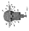
- a carrier 10, a door outer panel 11 and a tower 20 are shown in the drawings.
- the carrier 10 is mounted in the door interior of the inside of the door and comes to rest on the back 12 of the door outer panel 11.
- the tower 20 has in the present case a lock cylinder of the only one working end 15 can be seen, which cooperates with a lock not shown in detail inside the door.
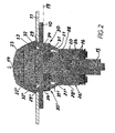
- a pulse spring whose windings 16 in the cross-sectional view of Fig. 2 are recognizable, ensures a defined zero position of the working end 15.
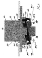
- the lock cylinder is how out Fig. 3 emerges, inserted from the outside of the door in the direction of the arrow 24.
- the carrier 10 has a passage 17 and the door outer panel 11 a cutout 18.
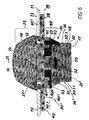
- the end position of the insertion movement is in Fig. 6 shown. As can be seen, then comes the tower 20 with its tower end 23 on the front side 13 of the door outer panel 11 to lie. The lock cylinder located inside the tower is then accessible from the outside of the door 13 for a key.
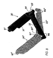
- the peculiarity of the invention is best seen in the cross-sectional view of Fig. 2 and in perspective representations of Fig. 7 and 8th to recognize.
- the invention has two control levers 30, 30 ', which are pivotally mounted on opposite sides of the tower 20, which by the position of the pivot axes 34, 34' in Fig. 2 is clear.
- the two control levers 30, 30 ' have an analogous structure, but are arranged in opposite directions to each other in the carrier and act together in unison with the tower 20 together. Because of their analogy, it is sufficient, based on Fig. 7 and 8th only to describe the structure of the one control lever 30, because it also determines the structure of the mirror image control lever 30 '.
- the control lever 30 includes three arms 31 to 33. These include first a locking arm 31 and a stop arm 32, the two each consist of transverse strips 35, 36. The longitudinal course of the strips 35, 36 extends parallel to the in Fig. 2 The two arms 31, 32 are thus formed by the cross section of the two strips 35, 36 and extend substantially parallel to the dot-dash line in Fig. 3 clarified tower axis 25.
- the third arm 33 should be referred to for even more apparent reasons "reinforcing arm”.
- the reinforcing arm 33 extends in the in Fig. 6 30.1 marked position of the control lever 30 substantially parallel to the aforementioned support plane 19 and thus perpendicular to the tower axis 25. The position 30.1 is then for the following reason a "locked position" of the control lever 30th
- the tower 20 has a rectangular cross-section with Fig. 6 recognizable, substantially planar side surfaces 26, 49, 26 '. On opposite side surfaces 26, 26 ', as is out Fig. 2 shows, the tower 20 with locking openings 21, 21 'provided. These consist of a continuous transverse channel 27, 27 ', the insertion of the movement 24 opposing inner channel side walls 28, 28' play a special role. In the final insertion position according to Fig. 2 namely, the two locking arms 31, 31 'engage in the locking openings 21, 21'.
- the tower 20 has in the transition region to its outer tower end 23 has a shoulder, in which there are two axial grooves 22, 22 ', which are open and linear in the insertion direction. In the case of insertion according to Fig. 2 drive the stop arms 32, 32 'in the axial grooves 22, 22' a.
- the pivot bearings 40, 40 'of the two control levers 30, 30' on the back 38 of the carrier 10 are arranged.
- spring means are provided, which consist of a formed on the carrier 10 spring tab 39 and 39 ', as from Fig. 4 can be seen. These spring lugs extend in extension of a section of the carrier-side counter bearing 42, 42 '.
- the spring lugs 39, 39 ' are endeavored already elsewhere, in connection with Fig. 2 explained torque 37 and 37 'on the two levers 30, 30' exercise.
- the support position 45, 45 'of the two-sided reinforcing arms 33, 33' is in the Fig. 6 . 7 indicated by the auxiliary lines 45, 45 '.
- the carrier 10 can withstand much higher extraction forces 14. It is advantageous at both ends of the in Fig. 7 shown strips 35, 36 provide two such reinforcing arms 33, 33 '. This gives in the blocking position 30.1, 30.1 'a frame-shaped structure, to which four reinforcing arms and the Both strips 31, 32 are involved. The tower 20 is then enclosed on all sides. This results in a very high pull-out strength.
Landscapes
- Lock And Its Accessories (AREA)
- Fittings On The Vehicle Exterior For Carrying Loads, And Devices For Holding Or Mounting Articles (AREA)
Claims (29)
- Poignée, pour portières ou couvercles de véhicules,
avec un support (10) servant de palier à la poignée et fixé à l'intérieur de la porte, depuis le côté intérieur de la portière (12),
avec une tour (20), soit présentant un cylindre de fermeture (15), soit réalisée sous forme d'élément factice de stylique,
tour qui est enfichée (24) après coup dans le support (10), depuis le côté extérieur de la portière, et dont l'extrémité de tour (23) vient se placer sur le côté extérieur (13) de la portière,
et avec une vis de sécurité (50), susceptible d'être vissée dans le support (10), assurant la position d'enfichage de la tour (20) dans le support (10),
caractérisée en ce que,
dans le support (10), est monté à pivotement au moins un levier de commande (30) présentant un bras de blocage (31),
en ce que la tour (20) comprend une ouverture de blocage (21) latérale pour le bras de blocage (31),
en ce que le levier de commande (30) est susceptible de pivoter, avec son bras de blocage (31), entre une position de blocage (30.1) s'engageant dans l'ouverture de blocage (21) de la tour (20), et une position de libération (30.2) se trouvant à l'extérieur de l'ouverture de blocage (21),
et en ce que la position de blocage (30.1) du levier de commande (30) est assurée au moyen de la vis de sécurité (50). - Poignée selon la revendication 1, caractérisée en ce que la tour (20) présente des surfaces de commande (43, 26), provoquant un mouvement de pivotement du levier de commande (30) lors de l'enfichage (24).
- Poignée selon la revendication 1 ou 2, caractérisée en ce que le levier de commande (30) présente un bras de butée (32) et la tour (20) présente une rainure axiale (22) ouverte axialement,
en ce que, lors de l'enfichage (24) de la tour (20), l'extrémité libre du bras de butée (32) pénètre dans la rainure axiale (22),
et en ce que l'extrémité introduite du bras de butée (32) vient en appui sur une paroi intérieure (29) de la rainure axiale (22), faisant qu'une continuation d'un mouvement de pivotement du levier de commande (30) est empêchée. - Poignée selon l'une des revendications 1 à 3, caractérisée en ce que le bras de blocage (31) et/ou le bras de butée (32) sont chacun composés de bandes (35, 36), réalisées d'une seule pièce avec les parties de palier de pivotement (41) du levier de commande (30),
et en ce que les bandes (35, 36) agissant en tant que bras de blocage (31) et/ou bras de butée (32) s'étendent certes sensiblement parallèlement à l'axe de palier de pivotement (34), mais transversalement à la direction d'enfichage (24) de la tour (20). - Poignée selon l'une ou plusieurs des revendications 1 à 4, caractérisée en ce que la tour (20) présente, au moins dans la zone axiale de l'ouverture de blocage (21), en observant en vue en coupe, un contour de forme rectangulaire.
- Poignée selon la revendication 4 ou 5, caractérisée en ce que l'ouverture de blocage (21) est composée d'un canal transversal (27) continu de façon linéaire, latéral, dans la tour (20),
en ce que, lorsque des forces d'extraction (14) sont exercées sur la tour (20) enfichée dans le support (10), la paroi latérale (28) intérieure du canal transversal (27) est pressée contre l'arête de bande libre par le bras de blocage (31) et exerce un couple de rotation (37) sur le levier de commande (30),
et en ce que ce couple de rotation (37) est supporté par la tour (20), par pressage de l'arête de bande libre du bras de butée (32) sur la paroi latérale extérieure (29) de la rainure axiale (22) linéaire. - Poignée selon l'une ou plusieurs des revendications 1 à 6, caractérisée en ce que les parties de palier (41) du levier de commande (30) sont logées à pivotement dans des parties de palier conjuguées (42) se trouvant sur le côté arrière (38) du support (10).
- Poignée selon l'une ou plusieurs des revendications 1 à 7, caractérisée en ce que les parties de palier du levier de commande (30) sont composées de deux tourillons de palier (41).
- Poignée selon la revendication 8, caractérisée en ce que les deux tourillons de palier (41) ressortent axialement aux extrémités de la bande (35, 36) servant de bras de blocage (31) et/ou de bras de butée (32) et s'étendent l'un par rapport à l'autre parallèlement et en sens inverse.
- Poignée selon l'une ou plusieurs des revendications 7 à 9, caractérisée en ce que les emplacements de contre-palier dans le support (10) sont composés de logements de palier (42), ouverts en direction du déplacement d'enfichage (24) de la tour (20).
- Poignée selon l'une ou plusieurs des revendications 1 à 10, caractérisée en ce que le support présente des moyens élastiques (39) visant à maintenir le levier de commande (30) pressé dans sa position de blocage (30.1).
- Poignée selon la revendication 11, caractérisée en ce que les moyens élastiques sont formés d'un ergot élastique (39) siégeant sur le support (10).
- Poignée selon la revendication 12, caractérisée en ce que l'ergot élastique (39) est réalisé d'une seule pièce à partir du matériau du support (10).
- Poignée selon la revendication 12, caractérisée en ce que l'ergot élastique (39) est réalisé à partir d'un prolongement d'un morceau partiel des emplacements de contre-palier (42) se trouvant sur le support (10).
- Poignée selon l'une ou plusieurs des revendications 1 à 14, caractérisée en ce que le levier de commande (30) présente un bras de renforcement (33), qui - en observant dans le cas où la tour (20) est enfichée - prend appui, à la position de blocage (30.1), sur la face arrière (38) du support (10).
- Poignée selon la revendication 15, caractérisée en ce que le bras de renforcement (33) s'étend le long d'une surface latérale (26) de la tour (20), voisine de la surface latérale (26), comportant l'ouverture de blocage (21), de la tour (20).
- Poignée selon l'une ou plusieurs des revendications 1 à 16, caractérisée en ce que le bras de renforcement (33) est réalisé de manière linéaire et, à la position de blocage (30.1), s'étend dans un plan parallèle (19) par rapport au canal transversal (27) de la tour (20) enfichée.
- Poignée selon la revendication 17, caractérisée en ce que le bras de renforcement (33) sert au mouvement de pivotement du levier de commande (30), entre la position de blocage (30.1) et la position de libération (30.2).
- Poignée selon la revendication 17 ou 18, caractérisée en ce que, lorsque le levier de commande (30) se trouve à la position de libération (30.2), le bras de renforcement (33) prend une allure d'inclinaison (44) par rapport au canal transversal (27) de la tour (20) enfichée.
- Poignée selon l'une ou plusieurs des revendications 15 à 19, caractérisée en ce que le levier de commande (30) présente deux bras de renforcement (33), entre lesquels la tour (20) est susceptible d'être enfichée (24) dans le support (10),
et en ce que les deux bras de renforcement (33), en cas d'enfichage, sont positionnés sur deux surfaces latérales (49), opposées l'une à l'autre, de la tour (20). - Poignée selon l'une ou plusieurs des revendications 1 à 20, caractérisée en ce que deux leviers de commande (30, 30') sont montés à pivotement sur le support (10), selon un agencement en sens inverse l'un par rapport à l'autre, et coopèrent avec la même tour (20).
- Poignée selon la revendication 21, caractérisée en ce que, lorsque les deux leviers de commande (30, 30') sont dans la position de blocage (30.1, 30.1'), les bras (33, 33') respectifs s'étendent par paires, les uns à côté des autres ou les uns au-dessus des autres dans le support (10) et prennent appui conjointement sur la face arrière (38) du support (10),
et en ce que la tour (20) est enfichée (24) dans le support (10), entre les deux paires de bras de renforcement (33, 33'). - Poignée selon les revendications 21 à 22, caractérisée en ce que, lorsque les deux leviers de commande (30, 30') sont dans la position de blocage (30.1, 30.1'), les deux bras de renforcement (33, 33') et les deux bandes (35, 36) forment un cadre fermé, entourant la tour (20) enfichée, dans une zone de hauteur.
- Poignée selon l'une ou plusieurs des revendications 21 à 23, caractérisée en ce que les deux extrémités des deux bras de renforcement (33, 33') de deux leviers de commande (30, 30') disposés selon une symétrie spéculaire sont munies, d'une part, de surfaces de coupole (46, 46') et, d'autre part, de surfaces de coupole conjuguées (47, 47'),
venant en prise ensemble lorsqu'on est à la position de blocage (30.1, 30.1'), et maintenant assemblés les bras de renforcement (30, 30') situés par paires les uns à côté des autres ou les uns au-dessus des autres. - Poignée selon la revendication 24, caractérisée en ce que les surfaces de coupole conjuguées sont composées de pièces de prolongement (47, 47') des tourillon de palier (41, 41') des deux leviers de commande (30, 30'), tandis que les surfaces de coupole sont formées de creusements (46, 46') sur les extrémités libres des bras de renforcement (33, 33'), recevant les tourillons de palier (41, 41') 41') lorsqu'on se trouve dans la position de blocage (30.1, 30.1').
- Poignée selon l'une ou plusieurs des revendications 1 à 25, caractérisée en ce que le support (10), conjointement avec les emplacements de palier conjugués (42, 42') et/ou le ou les leviers de commande (30, 30'), sont composés de matière synthétique.
- Poignée selon l'une ou plusieurs des revendications 1 à 26, caractérisée en ce que la vis de sécurité (50), à sa position assurée, bloque le levier de commande (30, 30') dans sa position de blocage (30.1, 30.1').
- Poignée selon la revendication 27, caractérisée en ce que la vis de sécurité (50) maintient le bras de renforcement (33, 33') dans sa position de pressage sur la face de pressage (38) du support (10).
- Poignée selon l'une ou plusieurs des revendications 1 à 28, caractérisée en ce que la vis de sécurité (50) fait partie d'une commande forcée, faisant pivoter le levier de commande (30) entre ses deux positions de pivotement (30.1 ; 30.2).
Applications Claiming Priority (2)
| Application Number | Priority Date | Filing Date | Title |
|---|---|---|---|
| DE10347296A DE10347296B4 (de) | 2003-10-08 | 2003-10-08 | Handhabe für Türen oder Klappen von Fahrzeugen |
| DE10347296 | 2003-10-08 |
Publications (3)
| Publication Number | Publication Date |
|---|---|
| EP1522656A2 EP1522656A2 (fr) | 2005-04-13 |
| EP1522656A3 EP1522656A3 (fr) | 2008-02-13 |
| EP1522656B1 true EP1522656B1 (fr) | 2009-06-03 |
Family
ID=34306372
Family Applications (1)
| Application Number | Title | Priority Date | Filing Date |
|---|---|---|---|
| EP04023639A Expired - Lifetime EP1522656B1 (fr) | 2003-10-08 | 2004-10-05 | Poignée de porte ou de couvercle d'un véhicule |
Country Status (3)
| Country | Link |
|---|---|
| EP (1) | EP1522656B1 (fr) |
| AT (1) | ATE433029T1 (fr) |
| DE (2) | DE10347296B4 (fr) |
Family Cites Families (3)
| Publication number | Priority date | Publication date | Assignee | Title |
|---|---|---|---|---|
| DE3030519C2 (de) * | 1980-08-13 | 1983-01-27 | Daimler-Benz Ag, 7000 Stuttgart | Außenliegender Ziehgriff, insbesondere für Kraftfahrzeugtüren |
| DE19950172B4 (de) * | 1999-10-19 | 2009-02-12 | Huf Hülsbeck & Fürst Gmbh & Co. Kg | Griffbeschlag, insbesondere für eine Kraftfahrzeugtür |
| DE10146026C1 (de) * | 2001-09-18 | 2002-10-31 | Huf Huelsbeck & Fuerst Gmbh | Griffbeschlag |
-
2003
- 2003-10-08 DE DE10347296A patent/DE10347296B4/de not_active Expired - Fee Related
-
2004
- 2004-10-05 AT AT04023639T patent/ATE433029T1/de not_active IP Right Cessation
- 2004-10-05 DE DE502004009555T patent/DE502004009555D1/de not_active Expired - Lifetime
- 2004-10-05 EP EP04023639A patent/EP1522656B1/fr not_active Expired - Lifetime
Also Published As
| Publication number | Publication date |
|---|---|
| DE10347296A1 (de) | 2005-05-19 |
| ATE433029T1 (de) | 2009-06-15 |
| EP1522656A2 (fr) | 2005-04-13 |
| DE10347296B4 (de) | 2005-12-29 |
| EP1522656A3 (fr) | 2008-02-13 |
| DE502004009555D1 (de) | 2009-07-16 |
Similar Documents
| Publication | Publication Date | Title |
|---|---|---|
| EP3612697B1 (fr) | Serrure pour véhicule à moteur | |
| DE69307433T2 (de) | Zentralisierter Steuermechanismus mit eingebauten Sicherheiten zur Verwendung in einer abgedichteten Übertragungseinrichtung zwischen zwei geschlossenen Räumen | |
| EP2877657B1 (fr) | Gâchette pour dispositif de protection d'accès à déverrouillage auxiliaire | |
| EP2581531B1 (fr) | Engrenage pour une espagnolette de fenêtre, de porte ou analogue | |
| DE3135401C2 (de) | Verriegelungseinrichtung für ein Tor mit einem ein- oder mehrteiligen Torblatt | |
| DE102007061055A1 (de) | Klappenanordnung | |
| EP2133494B1 (fr) | Dispositif de verrouillage de sécurité doté d'un dispositif de déverrouillage de secours | |
| DE69611719T2 (de) | Vorrichtung zur Führung, zum Antrieb und zur Verriegelung eines elektrischen oder elektronischen Ausrüstungseinschubs in einem Schrank | |
| DE69417499T2 (de) | Entkuppelbares Schloss für Kraftfahrzeuge und dgl. | |
| DE10021839A1 (de) | Elektromechanisch zu verriegelndes Möbelschloss | |
| DE19844593C1 (de) | Schließzylinder, insbesondere für Fahrzeuge | |
| EP2540616B1 (fr) | Mécanisme de fermeture pour portes coulissantes assistées | |
| DE102018124159A1 (de) | Flächenbündiger Betätigungsgriff für eine Schließvorrichtung | |
| DE10010501C2 (de) | Integrierte Schloß-/Griffanordnung | |
| EP0453626B1 (fr) | Dispositif de fermeture de levier pivotant et enfonçant muni d'une serrure | |
| DE102018133301A1 (de) | Schloss für ein Kraftfahrzeug | |
| DE10257688A1 (de) | Verschussvorrichtung für eine in einem Fahrzeug vorgesehene Öffnung mit einer einzigen Gleitführungsschiene sowie entsprechendes Fahrzeug | |
| EP1671001B1 (fr) | Serrure | |
| DE102006021172B4 (de) | Elektronischer Schlüssel mit mechanischem Notschlüssel für Verschlüsse in Fahrzeugen | |
| DE10036398A1 (de) | Vorrichtung zur Arretierung eines Schließzylindergehäuses | |
| DE2349760A1 (de) | Magnetisch betaetigbare steuereinrichtung | |
| WO2012126445A2 (fr) | Serrure de portière de véhicule à moteur | |
| DE10347296B4 (de) | Handhabe für Türen oder Klappen von Fahrzeugen | |
| DE19929103B4 (de) | Verschluss für Türen, Hauben, Klappen od.dgl., insbesondere Heckverschluss eines Fahrzeugs | |
| DE4405346C2 (de) | Vorrichtung zur Entriegelung und Verriegelung der Rücksitzlehne von Kfz |
Legal Events
| Date | Code | Title | Description |
|---|---|---|---|
| PUAI | Public reference made under article 153(3) epc to a published international application that has entered the european phase |
Free format text: ORIGINAL CODE: 0009012 |
|
| AK | Designated contracting states |
Kind code of ref document: A2 Designated state(s): AT BE BG CH CY CZ DE DK EE ES FI FR GB GR HU IE IT LI LU MC NL PL PT RO SE SI SK TR |
|
| AX | Request for extension of the european patent |
Extension state: AL HR LT LV MK |
|
| PUAL | Search report despatched |
Free format text: ORIGINAL CODE: 0009013 |
|
| AK | Designated contracting states |
Kind code of ref document: A3 Designated state(s): AT BE BG CH CY CZ DE DK EE ES FI FR GB GR HU IE IT LI LU MC NL PL PT RO SE SI SK TR |
|
| AX | Request for extension of the european patent |
Extension state: AL HR LT LV MK |
|
| 17P | Request for examination filed |
Effective date: 20080704 |
|
| AKX | Designation fees paid |
Designated state(s): AT BE BG CH CY CZ DE DK EE ES FI FR GB GR HU IE IT LI LU MC NL PL PT RO SE SI SK TR |
|
| GRAP | Despatch of communication of intention to grant a patent |
Free format text: ORIGINAL CODE: EPIDOSNIGR1 |
|
| GRAS | Grant fee paid |
Free format text: ORIGINAL CODE: EPIDOSNIGR3 |
|
| GRAA | (expected) grant |
Free format text: ORIGINAL CODE: 0009210 |
|
| AK | Designated contracting states |
Kind code of ref document: B1 Designated state(s): AT BE BG CH CY CZ DE DK EE ES FI FR GB GR HU IE IT LI LU MC NL PL PT RO SE SI SK TR |
|
| REG | Reference to a national code |
Ref country code: GB Ref legal event code: FG4D Free format text: NOT ENGLISH |
|
| REG | Reference to a national code |
Ref country code: CH Ref legal event code: EP |
|
| REG | Reference to a national code |
Ref country code: IE Ref legal event code: FG4D Free format text: LANGUAGE OF EP DOCUMENT: GERMAN |
|
| REF | Corresponds to: |
Ref document number: 502004009555 Country of ref document: DE Date of ref document: 20090716 Kind code of ref document: P |
|
| PG25 | Lapsed in a contracting state [announced via postgrant information from national office to epo] |
Ref country code: FI Free format text: LAPSE BECAUSE OF FAILURE TO SUBMIT A TRANSLATION OF THE DESCRIPTION OR TO PAY THE FEE WITHIN THE PRESCRIBED TIME-LIMIT Effective date: 20090603 |
|
| NLV1 | Nl: lapsed or annulled due to failure to fulfill the requirements of art. 29p and 29m of the patents act | ||
| PG25 | Lapsed in a contracting state [announced via postgrant information from national office to epo] |
Ref country code: SI Free format text: LAPSE BECAUSE OF FAILURE TO SUBMIT A TRANSLATION OF THE DESCRIPTION OR TO PAY THE FEE WITHIN THE PRESCRIBED TIME-LIMIT Effective date: 20090603 Ref country code: PL Free format text: LAPSE BECAUSE OF FAILURE TO SUBMIT A TRANSLATION OF THE DESCRIPTION OR TO PAY THE FEE WITHIN THE PRESCRIBED TIME-LIMIT Effective date: 20090603 Ref country code: NL Free format text: LAPSE BECAUSE OF FAILURE TO SUBMIT A TRANSLATION OF THE DESCRIPTION OR TO PAY THE FEE WITHIN THE PRESCRIBED TIME-LIMIT Effective date: 20090603 Ref country code: SE Free format text: LAPSE BECAUSE OF FAILURE TO SUBMIT A TRANSLATION OF THE DESCRIPTION OR TO PAY THE FEE WITHIN THE PRESCRIBED TIME-LIMIT Effective date: 20090903 |
|
| REG | Reference to a national code |
Ref country code: IE Ref legal event code: FD4D |
|
| PG25 | Lapsed in a contracting state [announced via postgrant information from national office to epo] |
Ref country code: IE Free format text: LAPSE BECAUSE OF FAILURE TO SUBMIT A TRANSLATION OF THE DESCRIPTION OR TO PAY THE FEE WITHIN THE PRESCRIBED TIME-LIMIT Effective date: 20090603 Ref country code: EE Free format text: LAPSE BECAUSE OF FAILURE TO SUBMIT A TRANSLATION OF THE DESCRIPTION OR TO PAY THE FEE WITHIN THE PRESCRIBED TIME-LIMIT Effective date: 20090603 Ref country code: CZ Free format text: LAPSE BECAUSE OF FAILURE TO SUBMIT A TRANSLATION OF THE DESCRIPTION OR TO PAY THE FEE WITHIN THE PRESCRIBED TIME-LIMIT Effective date: 20090603 Ref country code: ES Free format text: LAPSE BECAUSE OF FAILURE TO SUBMIT A TRANSLATION OF THE DESCRIPTION OR TO PAY THE FEE WITHIN THE PRESCRIBED TIME-LIMIT Effective date: 20090914 Ref country code: RO Free format text: LAPSE BECAUSE OF FAILURE TO SUBMIT A TRANSLATION OF THE DESCRIPTION OR TO PAY THE FEE WITHIN THE PRESCRIBED TIME-LIMIT Effective date: 20090603 |
|
| PG25 | Lapsed in a contracting state [announced via postgrant information from national office to epo] |
Ref country code: SK Free format text: LAPSE BECAUSE OF FAILURE TO SUBMIT A TRANSLATION OF THE DESCRIPTION OR TO PAY THE FEE WITHIN THE PRESCRIBED TIME-LIMIT Effective date: 20090603 |
|
| PG25 | Lapsed in a contracting state [announced via postgrant information from national office to epo] |
Ref country code: BG Free format text: LAPSE BECAUSE OF FAILURE TO SUBMIT A TRANSLATION OF THE DESCRIPTION OR TO PAY THE FEE WITHIN THE PRESCRIBED TIME-LIMIT Effective date: 20090903 Ref country code: PT Free format text: LAPSE BECAUSE OF FAILURE TO SUBMIT A TRANSLATION OF THE DESCRIPTION OR TO PAY THE FEE WITHIN THE PRESCRIBED TIME-LIMIT Effective date: 20091003 |
|
| PLBE | No opposition filed within time limit |
Free format text: ORIGINAL CODE: 0009261 |
|
| STAA | Information on the status of an ep patent application or granted ep patent |
Free format text: STATUS: NO OPPOSITION FILED WITHIN TIME LIMIT |
|
| BERE | Be: lapsed |
Owner name: HUF HULSBECK & FURST G.M.B.H. & CO. KG Effective date: 20091031 |
|
| PG25 | Lapsed in a contracting state [announced via postgrant information from national office to epo] |
Ref country code: DK Free format text: LAPSE BECAUSE OF FAILURE TO SUBMIT A TRANSLATION OF THE DESCRIPTION OR TO PAY THE FEE WITHIN THE PRESCRIBED TIME-LIMIT Effective date: 20090603 |
|
| 26N | No opposition filed |
Effective date: 20100304 |
|
| PG25 | Lapsed in a contracting state [announced via postgrant information from national office to epo] |
Ref country code: MC Free format text: LAPSE BECAUSE OF NON-PAYMENT OF DUE FEES Effective date: 20091031 |
|
| REG | Reference to a national code |
Ref country code: CH Ref legal event code: PL |
|
| PG25 | Lapsed in a contracting state [announced via postgrant information from national office to epo] |
Ref country code: CH Free format text: LAPSE BECAUSE OF NON-PAYMENT OF DUE FEES Effective date: 20091031 Ref country code: BE Free format text: LAPSE BECAUSE OF NON-PAYMENT OF DUE FEES Effective date: 20091031 Ref country code: LI Free format text: LAPSE BECAUSE OF NON-PAYMENT OF DUE FEES Effective date: 20091031 Ref country code: GR Free format text: LAPSE BECAUSE OF FAILURE TO SUBMIT A TRANSLATION OF THE DESCRIPTION OR TO PAY THE FEE WITHIN THE PRESCRIBED TIME-LIMIT Effective date: 20090904 |
|
| PG25 | Lapsed in a contracting state [announced via postgrant information from national office to epo] |
Ref country code: GB Free format text: LAPSE BECAUSE OF NON-PAYMENT OF DUE FEES Effective date: 20091005 |
|
| PG25 | Lapsed in a contracting state [announced via postgrant information from national office to epo] |
Ref country code: AT Free format text: LAPSE BECAUSE OF NON-PAYMENT OF DUE FEES Effective date: 20091005 |
|
| PG25 | Lapsed in a contracting state [announced via postgrant information from national office to epo] |
Ref country code: IT Free format text: LAPSE BECAUSE OF FAILURE TO SUBMIT A TRANSLATION OF THE DESCRIPTION OR TO PAY THE FEE WITHIN THE PRESCRIBED TIME-LIMIT Effective date: 20090603 |
|
| PG25 | Lapsed in a contracting state [announced via postgrant information from national office to epo] |
Ref country code: LU Free format text: LAPSE BECAUSE OF NON-PAYMENT OF DUE FEES Effective date: 20091005 |
|
| PG25 | Lapsed in a contracting state [announced via postgrant information from national office to epo] |
Ref country code: HU Free format text: LAPSE BECAUSE OF FAILURE TO SUBMIT A TRANSLATION OF THE DESCRIPTION OR TO PAY THE FEE WITHIN THE PRESCRIBED TIME-LIMIT Effective date: 20091204 |
|
| PG25 | Lapsed in a contracting state [announced via postgrant information from national office to epo] |
Ref country code: TR Free format text: LAPSE BECAUSE OF FAILURE TO SUBMIT A TRANSLATION OF THE DESCRIPTION OR TO PAY THE FEE WITHIN THE PRESCRIBED TIME-LIMIT Effective date: 20090603 |
|
| PG25 | Lapsed in a contracting state [announced via postgrant information from national office to epo] |
Ref country code: CY Free format text: LAPSE BECAUSE OF FAILURE TO SUBMIT A TRANSLATION OF THE DESCRIPTION OR TO PAY THE FEE WITHIN THE PRESCRIBED TIME-LIMIT Effective date: 20090603 |
|
| REG | Reference to a national code |
Ref country code: DE Ref legal event code: R084 Ref document number: 502004009555 Country of ref document: DE |
|
| REG | Reference to a national code |
Ref country code: FR Ref legal event code: PLFP Year of fee payment: 12 |
|
| REG | Reference to a national code |
Ref country code: FR Ref legal event code: PLFP Year of fee payment: 13 |
|
| REG | Reference to a national code |
Ref country code: FR Ref legal event code: PLFP Year of fee payment: 14 |
|
| PGFP | Annual fee paid to national office [announced via postgrant information from national office to epo] |
Ref country code: DE Payment date: 20171025 Year of fee payment: 14 |
|
| REG | Reference to a national code |
Ref country code: FR Ref legal event code: PLFP Year of fee payment: 15 |
|
| PGFP | Annual fee paid to national office [announced via postgrant information from national office to epo] |
Ref country code: FR Payment date: 20181026 Year of fee payment: 15 |
|
| REG | Reference to a national code |
Ref country code: DE Ref legal event code: R119 Ref document number: 502004009555 Country of ref document: DE |
|
| PG25 | Lapsed in a contracting state [announced via postgrant information from national office to epo] |
Ref country code: DE Free format text: LAPSE BECAUSE OF NON-PAYMENT OF DUE FEES Effective date: 20190501 |
|
| PG25 | Lapsed in a contracting state [announced via postgrant information from national office to epo] |
Ref country code: FR Free format text: LAPSE BECAUSE OF NON-PAYMENT OF DUE FEES Effective date: 20191031 |