EP2581531B1 - Engrenage pour une espagnolette de fenêtre, de porte ou analogue - Google Patents
Engrenage pour une espagnolette de fenêtre, de porte ou analogue Download PDFInfo
- Publication number
- EP2581531B1 EP2581531B1 EP11185232.3A EP11185232A EP2581531B1 EP 2581531 B1 EP2581531 B1 EP 2581531B1 EP 11185232 A EP11185232 A EP 11185232A EP 2581531 B1 EP2581531 B1 EP 2581531B1
- Authority
- EP
- European Patent Office
- Prior art keywords
- locking
- drive rod
- mechanism according
- connecting rod
- recess
- Prior art date
- Legal status (The legal status is an assumption and is not a legal conclusion. Google has not performed a legal analysis and makes no representation as to the accuracy of the status listed.)
- Active
Links
- 230000000903 blocking effect Effects 0.000 description 37
- 230000005540 biological transmission Effects 0.000 description 16
- 230000008878 coupling Effects 0.000 description 9
- 238000010168 coupling process Methods 0.000 description 9
- 238000005859 coupling reaction Methods 0.000 description 9
- 238000006073 displacement reaction Methods 0.000 description 4
- 230000009849 deactivation Effects 0.000 description 1
- 230000009977 dual effect Effects 0.000 description 1
- 238000004080 punching Methods 0.000 description 1
- 239000007787 solid Substances 0.000 description 1
Images


Classifications
-
- E—FIXED CONSTRUCTIONS
- E05—LOCKS; KEYS; WINDOW OR DOOR FITTINGS; SAFES
- E05C—BOLTS OR FASTENING DEVICES FOR WINGS, SPECIALLY FOR DOORS OR WINDOWS
- E05C9/00—Arrangements of simultaneously actuated bolts or other securing devices at well-separated positions on the same wing
- E05C9/04—Arrangements of simultaneously actuated bolts or other securing devices at well-separated positions on the same wing with two sliding bars moved in opposite directions when fastening or unfastening
- E05C9/041—Arrangements of simultaneously actuated bolts or other securing devices at well-separated positions on the same wing with two sliding bars moved in opposite directions when fastening or unfastening with rack and pinion mechanism
-
- E—FIXED CONSTRUCTIONS
- E05—LOCKS; KEYS; WINDOW OR DOOR FITTINGS; SAFES
- E05B—LOCKS; ACCESSORIES THEREFOR; HANDCUFFS
- E05B15/00—Other details of locks; Parts for engagement by bolts of fastening devices
- E05B15/004—Lost motion connections
-
- E—FIXED CONSTRUCTIONS
- E05—LOCKS; KEYS; WINDOW OR DOOR FITTINGS; SAFES
- E05B—LOCKS; ACCESSORIES THEREFOR; HANDCUFFS
- E05B17/00—Accessories in connection with locks
- E05B17/20—Means independent of the locking mechanism for preventing unauthorised opening, e.g. for securing the bolt in the fastening position
- E05B17/2007—Securing, deadlocking or "dogging" the bolt in the fastening position
- E05B17/2026—Securing, deadlocking or "dogging" the bolt in the fastening position automatic, i.e. actuated by a closed door position sensor
-
- E—FIXED CONSTRUCTIONS
- E05—LOCKS; KEYS; WINDOW OR DOOR FITTINGS; SAFES
- E05B—LOCKS; ACCESSORIES THEREFOR; HANDCUFFS
- E05B17/00—Accessories in connection with locks
- E05B17/20—Means independent of the locking mechanism for preventing unauthorised opening, e.g. for securing the bolt in the fastening position
- E05B17/2007—Securing, deadlocking or "dogging" the bolt in the fastening position
- E05B17/203—Securing, deadlocking or "dogging" the bolt in the fastening position not following the movement of the bolt
- E05B17/2038—Securing, deadlocking or "dogging" the bolt in the fastening position not following the movement of the bolt moving rectilinearly
Definitions
- the invention relates to a transmission for an espagnolette fitting of a window, a door or the like, with an actuating element for driving a drive rod, and a linearly movable transversely to the espagnolette movement locking element which cooperates in a locking position of the transmission with a locking contour such that a drive rod movement is prevented ,
- An espagnolette is usually only by means of an actuating element provided in the gear from a locking position can be moved to an open position.
- the actuator may be, for example, a rotatable by means of a handle nut or a gear.
- the coupling means are formed with play such that between the beginning of the rotation of the actuating element from its end position and the beginning of the displacement of the coupling slide from the closed position is an idle travel of the actuating element.
- the locking member is designed as a substantially flat locking lever, which is pivotable in the housing is arranged. Due to the design and arrangement of the locking lever is not excluded that this bends with a corresponding application of force or jumps out of the locked position.
- Object of the present invention is therefore to provide an actuating gear that avoids these disadvantages.
- a transmission for a drive rod fitting a window, a door or the like with an actuator for driving a drive rod of the transmission, and a linearly movable transversely to the drive rod movement locking element, in a locking position of the transmission with a locking contour of the drive rod such cooperates, that a drive rod movement is prevented, wherein a movable by means of the actuating element during a movement out of the locking position releasing element is provided which has an unlocking, with which the locking element can be brought into a release position.
- the blocking element can perform a linear movement transversely to the espagnolette movement direction, the blocking element can be small building and only has to put back the slightest path between a blocking position and an open position.
- the blocking element is linearly movable transversely to the direction of movement of the drive rod or to the longitudinal direction of the drive rod. It is therefore not to be feared that the blocking element is unintentionally swung out of the locking position. Furthermore, the blocking element can be made relatively solid, so as to design a reliable back pressure protection.
- the transmission preferably has a housing in which the moving parts of the transmission are mounted.
- the blocking element is guided on a housing contour.
- the housing contour may be formed as a blind hole in which the locking element is displaced.
- the blocking element can be supported on the wall of the blind hole, resulting in a very stable back pressure protection.
- the blocking element is supported by a spring element on the housing.
- the blocking element can be supported by the spring element at the bottom of the blind hole. Accordingly, if the drive rod is displaced via the actuating element in a locking position, the spring-loaded locking element can automatically enter into an operative connection with the locking contour. Thus, a reliable operation of the back pressure protection is ensured.
- the locking contour may be formed on the drive rod.
- a projection is provided on the drive rod as a locking contour, which is engaged behind in a locking position by the locking element.
- a particularly reliable back pressure protection results when two, in particular opposite recesses are provided on the drive rod, in which the locking element can engage in a locking position.
- the blocking element may have a ramp surface for the unlocking section.
- the ramp surface may for example be a bevel or be formed substantially dome-shaped.
- the release element in the drive rod longitudinal direction is relatively limited relative to the drive rod movable.
- the release element can be moved relative to the drive rod, whereby the Entsperrabites can cooperate with the locking element and can bring this out of engagement with the locking contour. Only with a further movement of the actuating element, the drive rod, after it has been unlocked, then be moved.
- the release element is guided on the drive rod.
- the drive rod may have a slot in which the release element is at least partially arranged.
- the release element can be displaced within the oblong hole limited relative to the drive rod. If the release element abuts one of the ends of the elongated hole, the drive rod can also be displaced via the release element.
- the release element cooperates with the actuating element and is used except for unlocking the locking element for displacement of the drive rod.
- the release element can therefore represent a coupling element which is arranged between the actuating element and drive rod.
- a locking projection is provided on the blocking element, which can engage in a corresponding recess of the release element, it can be indicated to the user by the latching that the actuating element and thus the entire espagnolette in one Locking position is located.
- the latching projection which engages in a recess of the release element, thus the shift position of the transmission can be made noticeable to a user.
- the latching projection may be formed as a ramp surface.
- the latching projection can thus represent the ramp surface with which the unlocking section cooperates.
- the locking projection can perform a dual function.
- the ramp surface may be formed, for example, as the surface of a dome.
- the locking projection may be wedge-shaped, so that there is a slope as a ramp surface.
- a second provided on the drive rod, spaced from the first recess in the longitudinal direction of the drive rod recess may be provided, with which cooperates the latching projection.
- a switching position for example, correspond to an opening position of the espagnolette fitting.
- further cutouts on the drive rod, which interact with the latching projection for example, could be displayed with a further switching position, a Kippö Maschinens sued the espagnolette for a user.
- a blocking element receptacle In the region of the second recess, a blocking element receptacle can be provided.
- this blocking element receptacle is not used for locking receiving the blocking element but provides a free space is, so that the latching projection can engage in the second recess.
- the recess is dimensioned so large that no blocking effect takes place and the blocking element can be displaced during a movement of the drive rod from the detent position.
- the recess extends symmetrically in two directions relative to the second recess, so that the drive rod can be moved in both directions without being blocked by the blocking element. It is also conceivable asymmetric design to lock in one direction and allow movement in another direction, for example, to limit the stroke of the transmission.
- FIG. 1 shows a transmission 1 of a drive rod fitting 2.
- the transmission 1 has an actuating element 3, which has a square socket 4, in which a handle can be inserted.
- the actuating element 3 is designed as a gear. It cooperates with a release element 5, which is arranged in a slot of a drive rod 6.
- a blocking element 7 is supported via a spring element 8 in the housing. In this case, the blocking element 7 is partially arranged and guided in a blind hole of the housing.
- the spring element 8 is supported at the end of the pocket hole. Accordingly, the blocking element 7 is linearly transversely displaceable, in particular perpendicular to the longitudinal direction of the drive rod 6 or to the direction of movement of the drive rod 6.
- a recess 9 is provided as a locking contour, with which the locking element 7 cooperates in a locking position of the espagnolette 2.
- Drive rod 6 has a recess 10 which can cooperate with a latching element.
- a further recess forming a blocking element receptacle 11 can be seen, which allows the blocking element 7 to be moved linearly transversely to the drive rod longitudinal direction when it cooperates with the latching projection arranged on the blocking element 7 with the recess 10.
- the espagnolette fitting 2 is shown in an open position.
- the actuating element 3 has been rotated counterclockwise out of an end position.
- the drive rod 6 has been adjusted by actuation of the actuating element 3 via the release element 5 in the open position to the right.
- the latching recess of the drive rod 6 is located above the blocking element 7, so that a latching projection 23 of the blocking element 7 lies in the opening 10.
- an open position of the espagnolette 2 is displayed to a user. In order to move the drive rod 6 out of this position, a sufficiently large force must first be expended in order to displace the blocking element 7 against the spring force of the spring element 8.
- FIG. 2b shows the espagnolette fitting 2 in a closed position or locking position, wherein the back pressure protection is active. It can be seen that the actuator 3 has been completely pivoted clockwise until it in the FIG. 2b shown
- the release element 5 has been displaced by the actuating element 3 relative to the drive rod 6 in a left end position in which the left end 24 of the release element 5 cooperates with a stop 25 of the drive rod 6.
- the drive rod 6 has therefore been displaced via the actuating element 3 and the release element 5 in a left end position.
- the latching projection 23 of the locking element 7 is located in a latching recess 26 of the release element 5.
- the espagnolette fitting 2 is in a locking position.
- projections of the locking element 7 engage in the recess 9 of the drive rod 6. This means that the drive rod 6 can not be displaced by external force on the drive rod 6 or a closing element which is arranged on the drive rod 6. The back pressure protection is therefore active.
- the Figure 2c shows the deactivation of the back pressure protection.
- the actuating element 3 is moved a little way counterclockwise.
- the release element 5 is displaced relative to the drive rod 6 in its right end position with respect to the drive rod 6.
- An unlocking section 27, which runs flush with the drive rod 6 below, moves over the latching projection 23, the surface of which represents a ramp surface here.
- the blocking element 7 is displaced linearly transversely to the driving rod movement direction against the spring force of the spring element 8.
- the projections of the locking element 7 get out of engagement with the recess 9 of the drive rod 6, so that the drive rod 6 is now released for movement.
- a further rotation of the actuating element 3 in the counterclockwise direction can now cause a displacement of the drive rod 6 to the right.
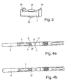
- FIG. 3 shows the blocking element 7 in a perspective view. It can be seen that the blocking element 7 has a dome-shaped elevation, which represents the latching projection 23. On the side elevations or projections 30, 31 can be seen, which can engage in the recess 9 of the drive rod 6, so as to lock the drive rod 6. Accordingly, if the projections 30, 31 are located in the recess 9, the back pressure protection is active. At the bottom of the locking element 7, a further dome-shaped elevation 32 can be seen. This serves to fix the position of the spring element eighth
- FIG. 4a shows a view from below of the drive rod 6.
- the recess 26 is located in the region of the recess 9 of the drive rod 6.
- the recess 9 can be made in a particularly simple manner by means of punching. In principle, however, other forms for a locking contour on the drive rod are conceivable. It is also conceivable, for example, to attach an additional element to the drive rod 6, thereby realizing a locking contour.
- the drive rod 6 also has the recess 10. In the region of the recess 10, the blocking element receptacle 11 can be seen.
- the blocking element receptacle 11 is longer than the recess 9. This is therefore to prevent blocking of the drive rod 6 when the latching projection 23 is located in the recess 10.
- the locking projection 23 is displaced by the drive rod 6 itself down or displaced, without causing the locking element 7 abuts the ends of the locking element holder 11.
- the locking element receiving 11 extends to both sides the recess 10 symmetrically to allow movement of the drive rod 6 in both directions.
- FIG. 4b essentially corresponds to the FIG. 4a with the difference that the release element 5 in the in the Figure 2c shown position.
- the unlocking section 27 has thus been pushed over the latching projection 23 and the blocking element 7 could thereby be displaced against the spring force.
Landscapes
- Engineering & Computer Science (AREA)
- Mechanical Engineering (AREA)
- Lock And Its Accessories (AREA)
Claims (12)
- Transmission (1) dévolue à une crémone (2) de fenêtre, de porte ou d'objet similaire, comprenant un élément d'actionnement (3) affecté à l'entraînement d'une tige de manoeuvre (6) de ladite transmission, ainsi qu'un élément de blocage (7) doué de mobilité linéaire, transversalement par rapport à la direction de mouvement de ladite tige de manoeuvre, et coopérant avec un profil de blocage de ladite tige de manoeuvre (6) dans une position de verrouillage de la transmission (1), de manière à empêcher un mouvement de ladite tige de manoeuvre, sachant qu'il est prévu un élément de libération (5) qui peut être mû au moyen dudit élément d'actionnement (3), lors d'un mouvement faisant quitter la position de verrouillage, et est doté d'une zone de déblocage (27) par laquelle ledit élément de blocage (7) peut être amené à une position de dégagement.
- Transmission selon la revendication 1, caractérisée par le fait que l'élément de blocage (7) est guidé sur un profil de boîtier.
- Transmission selon la revendication 1 ou 2, caractérisée par le fait que l'élément de blocage (7) est en appui sur le boîtier par l'intermédiaire d'un élément élastique (8).
- Transmission selon l'une des revendications précédentes, caractérisée par le fait que le profil de blocage est ménagé sur la tige de manoeuvre (6).
- Transmission selon l'une des revendications précédentes, caractérisée par le fait que l'élément de blocage (7) est pourvu d'une surface formant rampe d'ascension, dédiée à la zone de déblocage (27).
- Transmission selon l'une des revendications précédentes, caractérisée par le fait que l'élément de libération (5) est doué de mobilité limitée par rapport à la tige de manoeuvre (6) dans la direction longitudinale de ladite tige de manoeuvre.
- Transmission selon l'une des revendications précédentes, caractérisée par le fait que l'élément de libération (5) est guidé sur la tige de manoeuvre (6).
- Transmission selon l'une des revendications précédentes, caractérisée par le fait qu'une saillie encliquetable (23) prévue sur l'élément de blocage (7) pénètre, dans une position de verrouillage, dans un évidement correspondant (26) de l'élément de libération (5).
- Transmission selon la revendication 8, caractérisée par le fait que la saillie encliquetable (23) matérialise la surface formant rampe d'ascension.
- Transmission selon la revendication 8 ou 9, caractérisée par le fait qu'un second évidement (10), avec lequel la saillie encliquetable (23) coopère, est prévu sur la tige de manoeuvre (6).
- Transmission selon la revendication 10, caractérisée par le fait qu'un logement (11) de l'élément de blocage est prévu dans la région du second évidement (10).
- Fenêtre, porte ou objet similaire équipé(e) d'une transmission conforme à l'une des revendications précédentes.
Priority Applications (2)
| Application Number | Priority Date | Filing Date | Title |
|---|---|---|---|
| EP11185232.3A EP2581531B1 (fr) | 2011-10-14 | 2011-10-14 | Engrenage pour une espagnolette de fenêtre, de porte ou analogue |
| PL11185232T PL2581531T3 (pl) | 2011-10-14 | 2011-10-14 | Mechanizm dla okucia zasuwnicy okna, drzwi albo tym podobnych |
Applications Claiming Priority (1)
| Application Number | Priority Date | Filing Date | Title |
|---|---|---|---|
| EP11185232.3A EP2581531B1 (fr) | 2011-10-14 | 2011-10-14 | Engrenage pour une espagnolette de fenêtre, de porte ou analogue |
Publications (2)
| Publication Number | Publication Date |
|---|---|
| EP2581531A1 EP2581531A1 (fr) | 2013-04-17 |
| EP2581531B1 true EP2581531B1 (fr) | 2015-01-21 |
Family
ID=44785667
Family Applications (1)
| Application Number | Title | Priority Date | Filing Date |
|---|---|---|---|
| EP11185232.3A Active EP2581531B1 (fr) | 2011-10-14 | 2011-10-14 | Engrenage pour une espagnolette de fenêtre, de porte ou analogue |
Country Status (2)
| Country | Link |
|---|---|
| EP (1) | EP2581531B1 (fr) |
| PL (1) | PL2581531T3 (fr) |
Families Citing this family (14)
| Publication number | Priority date | Publication date | Assignee | Title |
|---|---|---|---|---|
| US8348308B2 (en) | 2008-12-19 | 2013-01-08 | Amesbury Group, Inc. | High security lock for door |
| US8939474B2 (en) | 2011-06-03 | 2015-01-27 | Amesbury Group, Inc. | Lock with sliding locking elements |
| US9428937B2 (en) | 2011-07-22 | 2016-08-30 | Amesbury Group, Inc. | Multi-point lock having sequentially-actuated locking elements |
| CA2882865C (fr) | 2012-08-31 | 2020-08-11 | Amesbury Group, Inc. | Mecanismes de verrou de porte passive |
| US9637957B2 (en) | 2012-11-06 | 2017-05-02 | Amesbury Group, Inc. | Automatically-extending remote door lock bolts |
| PL2784248T3 (pl) | 2013-03-26 | 2016-03-31 | Roto Frank Ag | Układ mechanizmu dla okucia zasuwnicowego |
| WO2016061473A1 (fr) | 2014-10-16 | 2016-04-21 | Bruce Hagemeyer | Verrou de porte coulissante à crochets opposés |
| US10968661B2 (en) | 2016-08-17 | 2021-04-06 | Amesbury Group, Inc. | Locking system having an electronic deadbolt |
| WO2018195081A1 (fr) | 2017-04-18 | 2018-10-25 | Amesbury Group, Inc. | Systèmes de pêne dormant électroniques modulaires |
| US10808424B2 (en) | 2017-05-01 | 2020-10-20 | Amesbury Group, Inc. | Modular multi-point lock |
| CA3012377A1 (fr) | 2017-07-25 | 2019-01-25 | Amesbury Group, Inc. | Poignee d'acces pour portes coulissantes |
| CA3036398A1 (fr) | 2018-03-12 | 2019-09-12 | Amesbury Group, Inc. | Systemes de pene dormant electronique |
| US11834866B2 (en) | 2018-11-06 | 2023-12-05 | Amesbury Group, Inc. | Flexible coupling for electronic deadbolt systems |
| US11661771B2 (en) | 2018-11-13 | 2023-05-30 | Amesbury Group, Inc. | Electronic drive for door locks |
Family Cites Families (3)
| Publication number | Priority date | Publication date | Assignee | Title |
|---|---|---|---|---|
| DE9210980U1 (fr) | 1992-08-17 | 1992-10-29 | Ferco International, Sarrebourg, Fr | |
| ITBO20010730A1 (it) * | 2001-11-29 | 2003-05-29 | Blindato Effeppi Srl | Dispositivo a serratura particolarmente per infissi |
| EP2339100B9 (fr) * | 2009-12-23 | 2013-07-03 | Roto Frank Ag | Agencement d'engrenage d'une ferrure de bielle, ferrure de bielle dotée d'un tel agencement d'engrenage ainsi que fenêtre, porte ou analogue dotés d'une telle ferrure de bielle |
-
2011
- 2011-10-14 EP EP11185232.3A patent/EP2581531B1/fr active Active
- 2011-10-14 PL PL11185232T patent/PL2581531T3/pl unknown
Also Published As
| Publication number | Publication date |
|---|---|
| EP2581531A1 (fr) | 2013-04-17 |
| PL2581531T3 (pl) | 2015-06-30 |
Similar Documents
| Publication | Publication Date | Title |
|---|---|---|
| EP2581531B1 (fr) | Engrenage pour une espagnolette de fenêtre, de porte ou analogue | |
| EP3884127B1 (fr) | Garniture de porte présentant une poignée pouvant être verrouillée d'un côté | |
| EP3165703A2 (fr) | Dispositif d'étanchéité abaissable | |
| EP3336284B1 (fr) | Corps de butée pour poignée d'actionnement, poignée d'actionnement et porte | |
| EP2031162B1 (fr) | Serrure de porte à verrouillage automatique | |
| EP2666938B1 (fr) | Serrure pour une porte | |
| EP3070238A1 (fr) | Dispositif de verrouillage pour une porte ou une fenêtre | |
| EP3026201A1 (fr) | Verrouillage supplementaire | |
| DE3831529C2 (de) | Treibstangenverschluß | |
| EP2792828A2 (fr) | Dispositif de maintien en position fermée pour portes coulissantes et dispositif de fermeture pour portes coulissantes | |
| EP2752537A2 (fr) | Agencement de ferrure | |
| EP3018273B1 (fr) | Verrouillage supplementaire | |
| EP2910713B1 (fr) | Serrure à mortaiser | |
| EP3266960A1 (fr) | Système comprenant un châssis dormant destiné à loger un cadre de vantail | |
| DE19809346B4 (de) | Elektromechanische Schließvorrichtung, insbesondere Schloß | |
| DE102016122879A1 (de) | Magnetverschluss | |
| DE202015104480U1 (de) | Kompaktes selbstverriegelndes Einsteckschloss | |
| WO2007104295A1 (fr) | Serrure pour une porte de maison ou d'appartement | |
| EP0606877B1 (fr) | Ferrure pour une serrure avec un pêne demi-tour et un pêne dormant | |
| DE102008016317B4 (de) | Schloss mit einer Anordnung zur Fallendrehung | |
| EP2754791B1 (fr) | Serrure de crémone | |
| DE102013111467A1 (de) | Multischloss | |
| EP3545151B1 (fr) | Dispositif de fermeture pour une trappe, une porte, un tiroir ou similaire | |
| EP3276107B1 (fr) | Ferrure de poignée de fenêtre | |
| DE102016122551A1 (de) | Flügelrahmen eines Fensters oder einer Tür |
Legal Events
| Date | Code | Title | Description |
|---|---|---|---|
| PUAI | Public reference made under article 153(3) epc to a published international application that has entered the european phase |
Free format text: ORIGINAL CODE: 0009012 |
|
| 17P | Request for examination filed |
Effective date: 20121107 |
|
| AK | Designated contracting states |
Kind code of ref document: A1 Designated state(s): AL AT BE BG CH CY CZ DE DK EE ES FI FR GB GR HR HU IE IS IT LI LT LU LV MC MK MT NL NO PL PT RO RS SE SI SK SM TR |
|
| AX | Request for extension of the european patent |
Extension state: BA ME |
|
| GRAP | Despatch of communication of intention to grant a patent |
Free format text: ORIGINAL CODE: EPIDOSNIGR1 |
|
| INTG | Intention to grant announced |
Effective date: 20131118 |
|
| 17Q | First examination report despatched |
Effective date: 20140522 |
|
| GRAP | Despatch of communication of intention to grant a patent |
Free format text: ORIGINAL CODE: EPIDOSNIGR1 |
|
| INTG | Intention to grant announced |
Effective date: 20141013 |
|
| GRAS | Grant fee paid |
Free format text: ORIGINAL CODE: EPIDOSNIGR3 |
|
| GRAA | (expected) grant |
Free format text: ORIGINAL CODE: 0009210 |
|
| AK | Designated contracting states |
Kind code of ref document: B1 Designated state(s): AL AT BE BG CH CY CZ DE DK EE ES FI FR GB GR HR HU IE IS IT LI LT LU LV MC MK MT NL NO PL PT RO RS SE SI SK SM TR |
|
| REG | Reference to a national code |
Ref country code: GB Ref legal event code: FG4D Free format text: NOT ENGLISH |
|
| REG | Reference to a national code |
Ref country code: CH Ref legal event code: EP |
|
| REG | Reference to a national code |
Ref country code: IE Ref legal event code: FG4D Free format text: LANGUAGE OF EP DOCUMENT: GERMAN |
|
| REG | Reference to a national code |
Ref country code: DE Ref legal event code: R096 Ref document number: 502011005702 Country of ref document: DE Effective date: 20150305 |
|
| REG | Reference to a national code |
Ref country code: AT Ref legal event code: REF Ref document number: 709284 Country of ref document: AT Kind code of ref document: T Effective date: 20150315 |
|
| REG | Reference to a national code |
Ref country code: NL Ref legal event code: VDEP Effective date: 20150121 |
|
| REG | Reference to a national code |
Ref country code: LT Ref legal event code: MG4D |
|
| REG | Reference to a national code |
Ref country code: PL Ref legal event code: T3 |
|
| PG25 | Lapsed in a contracting state [announced via postgrant information from national office to epo] |
Ref country code: HR Free format text: LAPSE BECAUSE OF FAILURE TO SUBMIT A TRANSLATION OF THE DESCRIPTION OR TO PAY THE FEE WITHIN THE PRESCRIBED TIME-LIMIT Effective date: 20150121 Ref country code: BG Free format text: LAPSE BECAUSE OF FAILURE TO SUBMIT A TRANSLATION OF THE DESCRIPTION OR TO PAY THE FEE WITHIN THE PRESCRIBED TIME-LIMIT Effective date: 20150421 Ref country code: LT Free format text: LAPSE BECAUSE OF FAILURE TO SUBMIT A TRANSLATION OF THE DESCRIPTION OR TO PAY THE FEE WITHIN THE PRESCRIBED TIME-LIMIT Effective date: 20150121 Ref country code: SE Free format text: LAPSE BECAUSE OF FAILURE TO SUBMIT A TRANSLATION OF THE DESCRIPTION OR TO PAY THE FEE WITHIN THE PRESCRIBED TIME-LIMIT Effective date: 20150121 Ref country code: NO Free format text: LAPSE BECAUSE OF FAILURE TO SUBMIT A TRANSLATION OF THE DESCRIPTION OR TO PAY THE FEE WITHIN THE PRESCRIBED TIME-LIMIT Effective date: 20150421 Ref country code: FI Free format text: LAPSE BECAUSE OF FAILURE TO SUBMIT A TRANSLATION OF THE DESCRIPTION OR TO PAY THE FEE WITHIN THE PRESCRIBED TIME-LIMIT Effective date: 20150121 Ref country code: ES Free format text: LAPSE BECAUSE OF FAILURE TO SUBMIT A TRANSLATION OF THE DESCRIPTION OR TO PAY THE FEE WITHIN THE PRESCRIBED TIME-LIMIT Effective date: 20150121 |
|
| PG25 | Lapsed in a contracting state [announced via postgrant information from national office to epo] |
Ref country code: GR Free format text: LAPSE BECAUSE OF FAILURE TO SUBMIT A TRANSLATION OF THE DESCRIPTION OR TO PAY THE FEE WITHIN THE PRESCRIBED TIME-LIMIT Effective date: 20150422 Ref country code: NL Free format text: LAPSE BECAUSE OF FAILURE TO SUBMIT A TRANSLATION OF THE DESCRIPTION OR TO PAY THE FEE WITHIN THE PRESCRIBED TIME-LIMIT Effective date: 20150121 Ref country code: LV Free format text: LAPSE BECAUSE OF FAILURE TO SUBMIT A TRANSLATION OF THE DESCRIPTION OR TO PAY THE FEE WITHIN THE PRESCRIBED TIME-LIMIT Effective date: 20150121 Ref country code: RS Free format text: LAPSE BECAUSE OF FAILURE TO SUBMIT A TRANSLATION OF THE DESCRIPTION OR TO PAY THE FEE WITHIN THE PRESCRIBED TIME-LIMIT Effective date: 20150121 Ref country code: IS Free format text: LAPSE BECAUSE OF FAILURE TO SUBMIT A TRANSLATION OF THE DESCRIPTION OR TO PAY THE FEE WITHIN THE PRESCRIBED TIME-LIMIT Effective date: 20150521 |
|
| REG | Reference to a national code |
Ref country code: DE Ref legal event code: R097 Ref document number: 502011005702 Country of ref document: DE |
|
| REG | Reference to a national code |
Ref country code: FR Ref legal event code: PLFP Year of fee payment: 5 |
|
| PG25 | Lapsed in a contracting state [announced via postgrant information from national office to epo] |
Ref country code: RO Free format text: LAPSE BECAUSE OF FAILURE TO SUBMIT A TRANSLATION OF THE DESCRIPTION OR TO PAY THE FEE WITHIN THE PRESCRIBED TIME-LIMIT Effective date: 20150121 Ref country code: EE Free format text: LAPSE BECAUSE OF FAILURE TO SUBMIT A TRANSLATION OF THE DESCRIPTION OR TO PAY THE FEE WITHIN THE PRESCRIBED TIME-LIMIT Effective date: 20150121 Ref country code: SK Free format text: LAPSE BECAUSE OF FAILURE TO SUBMIT A TRANSLATION OF THE DESCRIPTION OR TO PAY THE FEE WITHIN THE PRESCRIBED TIME-LIMIT Effective date: 20150121 Ref country code: CZ Free format text: LAPSE BECAUSE OF FAILURE TO SUBMIT A TRANSLATION OF THE DESCRIPTION OR TO PAY THE FEE WITHIN THE PRESCRIBED TIME-LIMIT Effective date: 20150121 Ref country code: DK Free format text: LAPSE BECAUSE OF FAILURE TO SUBMIT A TRANSLATION OF THE DESCRIPTION OR TO PAY THE FEE WITHIN THE PRESCRIBED TIME-LIMIT Effective date: 20150121 |
|
| PLBE | No opposition filed within time limit |
Free format text: ORIGINAL CODE: 0009261 |
|
| STAA | Information on the status of an ep patent application or granted ep patent |
Free format text: STATUS: NO OPPOSITION FILED WITHIN TIME LIMIT |
|
| 26N | No opposition filed |
Effective date: 20151022 |
|
| PG25 | Lapsed in a contracting state [announced via postgrant information from national office to epo] |
Ref country code: IT Free format text: LAPSE BECAUSE OF FAILURE TO SUBMIT A TRANSLATION OF THE DESCRIPTION OR TO PAY THE FEE WITHIN THE PRESCRIBED TIME-LIMIT Effective date: 20150121 |
|
| PG25 | Lapsed in a contracting state [announced via postgrant information from national office to epo] |
Ref country code: SI Free format text: LAPSE BECAUSE OF FAILURE TO SUBMIT A TRANSLATION OF THE DESCRIPTION OR TO PAY THE FEE WITHIN THE PRESCRIBED TIME-LIMIT Effective date: 20150121 |
|
| PG25 | Lapsed in a contracting state [announced via postgrant information from national office to epo] |
Ref country code: LU Free format text: LAPSE BECAUSE OF FAILURE TO SUBMIT A TRANSLATION OF THE DESCRIPTION OR TO PAY THE FEE WITHIN THE PRESCRIBED TIME-LIMIT Effective date: 20151014 |
|
| REG | Reference to a national code |
Ref country code: CH Ref legal event code: PL |
|
| PG25 | Lapsed in a contracting state [announced via postgrant information from national office to epo] |
Ref country code: MC Free format text: LAPSE BECAUSE OF FAILURE TO SUBMIT A TRANSLATION OF THE DESCRIPTION OR TO PAY THE FEE WITHIN THE PRESCRIBED TIME-LIMIT Effective date: 20150121 |
|
| REG | Reference to a national code |
Ref country code: IE Ref legal event code: MM4A |
|
| PG25 | Lapsed in a contracting state [announced via postgrant information from national office to epo] |
Ref country code: LI Free format text: LAPSE BECAUSE OF NON-PAYMENT OF DUE FEES Effective date: 20151031 Ref country code: CH Free format text: LAPSE BECAUSE OF NON-PAYMENT OF DUE FEES Effective date: 20151031 |
|
| REG | Reference to a national code |
Ref country code: FR Ref legal event code: PLFP Year of fee payment: 6 |
|
| PG25 | Lapsed in a contracting state [announced via postgrant information from national office to epo] |
Ref country code: IE Free format text: LAPSE BECAUSE OF NON-PAYMENT OF DUE FEES Effective date: 20151014 |
|
| PG25 | Lapsed in a contracting state [announced via postgrant information from national office to epo] |
Ref country code: SM Free format text: LAPSE BECAUSE OF FAILURE TO SUBMIT A TRANSLATION OF THE DESCRIPTION OR TO PAY THE FEE WITHIN THE PRESCRIBED TIME-LIMIT Effective date: 20150121 Ref country code: HU Free format text: LAPSE BECAUSE OF FAILURE TO SUBMIT A TRANSLATION OF THE DESCRIPTION OR TO PAY THE FEE WITHIN THE PRESCRIBED TIME-LIMIT; INVALID AB INITIO Effective date: 20111014 |
|
| PG25 | Lapsed in a contracting state [announced via postgrant information from national office to epo] |
Ref country code: CY Free format text: LAPSE BECAUSE OF FAILURE TO SUBMIT A TRANSLATION OF THE DESCRIPTION OR TO PAY THE FEE WITHIN THE PRESCRIBED TIME-LIMIT Effective date: 20150121 |
|
| PG25 | Lapsed in a contracting state [announced via postgrant information from national office to epo] |
Ref country code: BE Free format text: LAPSE BECAUSE OF NON-PAYMENT OF DUE FEES Effective date: 20151031 |
|
| PG25 | Lapsed in a contracting state [announced via postgrant information from national office to epo] |
Ref country code: MT Free format text: LAPSE BECAUSE OF FAILURE TO SUBMIT A TRANSLATION OF THE DESCRIPTION OR TO PAY THE FEE WITHIN THE PRESCRIBED TIME-LIMIT Effective date: 20150121 |
|
| REG | Reference to a national code |
Ref country code: FR Ref legal event code: PLFP Year of fee payment: 7 |
|
| PG25 | Lapsed in a contracting state [announced via postgrant information from national office to epo] |
Ref country code: PT Free format text: LAPSE BECAUSE OF FAILURE TO SUBMIT A TRANSLATION OF THE DESCRIPTION OR TO PAY THE FEE WITHIN THE PRESCRIBED TIME-LIMIT Effective date: 20150121 Ref country code: MK Free format text: LAPSE BECAUSE OF FAILURE TO SUBMIT A TRANSLATION OF THE DESCRIPTION OR TO PAY THE FEE WITHIN THE PRESCRIBED TIME-LIMIT Effective date: 20150121 |
|
| REG | Reference to a national code |
Ref country code: FR Ref legal event code: PLFP Year of fee payment: 8 |
|
| PG25 | Lapsed in a contracting state [announced via postgrant information from national office to epo] |
Ref country code: AL Free format text: LAPSE BECAUSE OF FAILURE TO SUBMIT A TRANSLATION OF THE DESCRIPTION OR TO PAY THE FEE WITHIN THE PRESCRIBED TIME-LIMIT Effective date: 20150121 |
|
| PGFP | Annual fee paid to national office [announced via postgrant information from national office to epo] |
Ref country code: PL Payment date: 20180911 Year of fee payment: 8 |
|
| PGFP | Annual fee paid to national office [announced via postgrant information from national office to epo] |
Ref country code: IT Payment date: 20181022 Year of fee payment: 11 |
|
| PGFP | Annual fee paid to national office [announced via postgrant information from national office to epo] |
Ref country code: DE Payment date: 20191025 Year of fee payment: 9 |
|
| PGFP | Annual fee paid to national office [announced via postgrant information from national office to epo] |
Ref country code: AT Payment date: 20191018 Year of fee payment: 9 Ref country code: TR Payment date: 20191010 Year of fee payment: 9 |
|
| PG25 | Lapsed in a contracting state [announced via postgrant information from national office to epo] |
Ref country code: FR Free format text: LAPSE BECAUSE OF NON-PAYMENT OF DUE FEES Effective date: 20191031 |
|
| REG | Reference to a national code |
Ref country code: DE Ref legal event code: R119 Ref document number: 502011005702 Country of ref document: DE |
|
| REG | Reference to a national code |
Ref country code: AT Ref legal event code: MM01 Ref document number: 709284 Country of ref document: AT Kind code of ref document: T Effective date: 20201014 |
|
| PG25 | Lapsed in a contracting state [announced via postgrant information from national office to epo] |
Ref country code: DE Free format text: LAPSE BECAUSE OF NON-PAYMENT OF DUE FEES Effective date: 20210501 |
|
| PG25 | Lapsed in a contracting state [announced via postgrant information from national office to epo] |
Ref country code: AT Free format text: LAPSE BECAUSE OF NON-PAYMENT OF DUE FEES Effective date: 20201014 |
|
| PG25 | Lapsed in a contracting state [announced via postgrant information from national office to epo] |
Ref country code: PL Free format text: LAPSE BECAUSE OF NON-PAYMENT OF DUE FEES Effective date: 20191014 |
|
| PG25 | Lapsed in a contracting state [announced via postgrant information from national office to epo] |
Ref country code: TR Free format text: LAPSE BECAUSE OF NON-PAYMENT OF DUE FEES Effective date: 20201014 |
|
| PGFP | Annual fee paid to national office [announced via postgrant information from national office to epo] |
Ref country code: GB Payment date: 20231025 Year of fee payment: 13 |