EP1522456A2 - Vorrichtung zur automatischen Einstellung der Richtung einer optischen Achse eines Autoscheinwerfers - Google Patents
Vorrichtung zur automatischen Einstellung der Richtung einer optischen Achse eines Autoscheinwerfers Download PDFInfo
- Publication number
- EP1522456A2 EP1522456A2 EP04024096A EP04024096A EP1522456A2 EP 1522456 A2 EP1522456 A2 EP 1522456A2 EP 04024096 A EP04024096 A EP 04024096A EP 04024096 A EP04024096 A EP 04024096A EP 1522456 A2 EP1522456 A2 EP 1522456A2
- Authority
- EP
- European Patent Office
- Prior art keywords
- filtering
- steering angle
- light axis
- swivel
- angle
- Prior art date
- Legal status (The legal status is an assumption and is not a legal conclusion. Google has not performed a legal analysis and makes no representation as to the accuracy of the status listed.)
- Granted
Links
Images


Classifications
-
- B—PERFORMING OPERATIONS; TRANSPORTING
- B60—VEHICLES IN GENERAL
- B60Q—ARRANGEMENT OF SIGNALLING OR LIGHTING DEVICES, THE MOUNTING OR SUPPORTING THEREOF OR CIRCUITS THEREFOR, FOR VEHICLES IN GENERAL
- B60Q1/00—Arrangement of optical signalling or lighting devices, the mounting or supporting thereof or circuits therefor
- B60Q1/02—Arrangement of optical signalling or lighting devices, the mounting or supporting thereof or circuits therefor the devices being primarily intended to illuminate the way ahead or to illuminate other areas of way or environments
- B60Q1/04—Arrangement of optical signalling or lighting devices, the mounting or supporting thereof or circuits therefor the devices being primarily intended to illuminate the way ahead or to illuminate other areas of way or environments the devices being headlights
- B60Q1/06—Arrangement of optical signalling or lighting devices, the mounting or supporting thereof or circuits therefor the devices being primarily intended to illuminate the way ahead or to illuminate other areas of way or environments the devices being headlights adjustable, e.g. remotely-controlled from inside vehicle
- B60Q1/08—Arrangement of optical signalling or lighting devices, the mounting or supporting thereof or circuits therefor the devices being primarily intended to illuminate the way ahead or to illuminate other areas of way or environments the devices being headlights adjustable, e.g. remotely-controlled from inside vehicle automatically
- B60Q1/12—Arrangement of optical signalling or lighting devices, the mounting or supporting thereof or circuits therefor the devices being primarily intended to illuminate the way ahead or to illuminate other areas of way or environments the devices being headlights adjustable, e.g. remotely-controlled from inside vehicle automatically due to steering position
-
- B—PERFORMING OPERATIONS; TRANSPORTING
- B60—VEHICLES IN GENERAL
- B60Q—ARRANGEMENT OF SIGNALLING OR LIGHTING DEVICES, THE MOUNTING OR SUPPORTING THEREOF OR CIRCUITS THEREFOR, FOR VEHICLES IN GENERAL
- B60Q2300/00—Indexing codes for automatically adjustable headlamps or automatically dimmable headlamps
- B60Q2300/10—Indexing codes relating to particular vehicle conditions
- B60Q2300/12—Steering parameters
- B60Q2300/122—Steering angle
-
- B—PERFORMING OPERATIONS; TRANSPORTING
- B60—VEHICLES IN GENERAL
- B60Q—ARRANGEMENT OF SIGNALLING OR LIGHTING DEVICES, THE MOUNTING OR SUPPORTING THEREOF OR CIRCUITS THEREFOR, FOR VEHICLES IN GENERAL
- B60Q2300/00—Indexing codes for automatically adjustable headlamps or automatically dimmable headlamps
- B60Q2300/10—Indexing codes relating to particular vehicle conditions
- B60Q2300/12—Steering parameters
- B60Q2300/124—Steering speed
-
- B—PERFORMING OPERATIONS; TRANSPORTING
- B60—VEHICLES IN GENERAL
- B60Q—ARRANGEMENT OF SIGNALLING OR LIGHTING DEVICES, THE MOUNTING OR SUPPORTING THEREOF OR CIRCUITS THEREFOR, FOR VEHICLES IN GENERAL
- B60Q2300/00—Indexing codes for automatically adjustable headlamps or automatically dimmable headlamps
- B60Q2300/10—Indexing codes relating to particular vehicle conditions
- B60Q2300/12—Steering parameters
- B60Q2300/126—Hysteresis behavior based on steering
-
- B—PERFORMING OPERATIONS; TRANSPORTING
- B60—VEHICLES IN GENERAL
- B60Q—ARRANGEMENT OF SIGNALLING OR LIGHTING DEVICES, THE MOUNTING OR SUPPORTING THEREOF OR CIRCUITS THEREFOR, FOR VEHICLES IN GENERAL
- B60Q2300/00—Indexing codes for automatically adjustable headlamps or automatically dimmable headlamps
- B60Q2300/10—Indexing codes relating to particular vehicle conditions
- B60Q2300/12—Steering parameters
- B60Q2300/128—Steering dead zone
Definitions
- the present invention relates to an apparatus for automatically adjusting a light axis or a lighting area of a light beam emitted from a vehicle headlight in the horizontal direction on the basis of a steering angle of a steering wheel.
- the apparatus disclosed in this document has a problem in that the light axis of the vehicle headlight may be swayed to the right and left unnecessary if the steering wheel is moved beyond a certain dead zone of the steering wheel even when the vehicle is in a straight-running state, which causes the driver of the vehicle to feel awkwardness in the control of the beam patterns.
- the apparatus for automatically adjusting a direction of a light axis of a vehicle headlight of the present invention has a configuration including:
- the swivel control unit may have a first filtering unit generating a filtered steering angle by subjecting the steering angle detected by the steering angle sensor to a first filtering process when the steering angle is within a straight running range around a neutral angular position of the steering wheel and to a second filtering process whose filtering strength is weaker than a filtering strength of the first filtering process when the steering angle is within one of turning ranges which interpose therebetween the straight running range.
- the straight running range may be a range extending from +10 degrees through the neutral angular position (0 degrees) to -10 degrees, so that it can be determined easily whether the vehicle is running straight or is turning, even when the steering wheel is moved slightly by the driver's steering operations or by the behavior of the tires when the vehicle is running on the road with irregularities such as wheel ruts.
- the filtering strength of the first filtering process may be twice (or four times) or more that of the second filtering process to suppress unnecessary movements of the light axis of the headlight.
- the first filtering unit may subject the steering angle to a third filtering process having a filtering strength which is equal to, or is 70%, or less of that of the filtering process of the second filtering process upon detecting that the steering wheel is being moved back or moved farther away at a rate faster than a predetermined value, so that the light axis of the vehicle headlight well follows the movements of the steering wheel while the vehicle is turning.
- the first filtering unit may weaken continuously or in stages the filtering strength of the second filtering process when the steering angle is changed into one of the turning ranges from the straight running range, so that it becomes possible to avoid any awkward sensations for the driver in the control of beam patterns.
- the swivel control unit may have a swivel angle calculating unit calculating a primary swivel angle depending on the filtered steering angle generated by the first filtering unit, a second filtering unit generating a target swivel angle by filtering the primary swivel angle, and an actuator adjusting the direction of the light axis of said vehicle headlight in accordance with the target swivel angle, the second filtering unit varying a filtering strength thereof depending on the difference between the primary swivel angle and the actual swivel angle corresponding to the direction of the light axis
- the second filtering unit may subject the primary swivel angle to a weak filtering when the difference between the primary swivel angle and the actual swivel angle is larger than a predetermined value, and to a strong filtering when the difference is equal to or smaller than the predetermined value, so that fluctuation of the light axis of the vehicle headlight can be suppressed while the vehicle is turning.
- the filtering strength of the second filtering unit when the steering wheel is being moved back is weaker than when the steering wheel is being moved farther away.
- Fig. 1 shows an overall structure of an apparatus for automatically adjusting a direction of a light axis of a vehicle headlight according to an embodiment of the invention.
- 10L and 10R denote left and right vehicle headlights, respectively.
- the headlights 10L and 10R are linked to actuators 11L and 11R for adjusting the light axes of the headlights 10L and 10R in the horizontal direction.
- An ECU (Electronic Control Unit) 20 includes a CPU 21 for executing various processings, a ROM 22 for storing control programs, control maps, etc., a RAM 23 for temporarily storing various data, a B/U (Back Up) RAM 24, an input-output circuit 25, and a bus line 26 for connecting these elements.
- the ECU 20 receives an output signal from a left wheel speed sensor 16L detecting a left wheel speed VL, an output signal from a right wheel speed sensor 16R detecting a right wheel speed VR, an output signal from a steering angle sensor 18 detecting a steering angle ⁇ of a steering wheel 17, and various sensor signals from other sensors, not illustrated.
- the actuators 11L and 11R act to adjust horizontally the directions of the light axes of the headlights 10L and 10R in accordance with signals outputted from the ECU 20.
- Fig. 2 shows beam patterns of the headlight 10R and 10L (low beam).
- the heavy solid line 10L-N represents a beam pattern of the headlight 10L when the steering wheel is in its neutral angular position.
- the arched arrow SL represents a swivel range within which the light axis of the headlight 10L can be swiveled in accordance with the steering angle of the steering wheel.
- the chain double-dashed lines 10L-R and 10L-L represent beam patterns of the headlight 10L when the light axis of the headlight 10L is in the rightmost position and the leftmost position within the swivel range, respectively.
- the heavy solid line 10R-N represents a beam pattern of the headlight 10R when the steering wheel is in the neutral angular position.
- the arched arrow SR represents a swivel range within which the light axis of the headlight 10R can be swiveled in accordance with the steering angle of the steering wheel.
- the chain double-dashed lines 10R-R and 10R-L represent beam patterns of the headlight 10R when the light axis of the headlight 10R is in the rightmost position and the leftmost position within the swivel range, respectively.
- the swivel ranges SL and SR should provide the driver with good visibility in the leftward or rightward direction when the driver turns the steering wheel to the left or right without a sacrifice of visibility in the forward direction. Accordingly, as shown in Fig. 2, a portion of the swivel range SR at the right of the initial angular position is wider than that of the swivel range SL so that the variation of the light axis of the headlight 10R is larger than that of the headlight 10L when the driver turns the steering wheel to the right.
- a portion of the swivel range SL at the left of the initial angular position is wider than that of the swivel range SR so that the variation of the light axis of the headlight 10L is larger than that of the headlight 10R when the driver turns the steering wheel to the left.
- Fig. 3 is a signal flow diagram of the apparatus according to this embodiment.
- the steering angle ⁇ detected by the steering angle sensor 18 is subjected to a steering angle filtering process P2 to generate a filtered steering angle ⁇ F by use of a filter F (not illustrated) which a steering-angle-filter selecting process P1 selects on the basis of the steering angle ⁇ inputted thereto.
- the filtered steering angle ⁇ F is subjected to a primary swivel angle calculating process P3 to generate a primary swivel angle SWC.
- the primary swivel angle SWC is subjected to a target swivel angle filtering process P5 to generate a target swivel angle SWT by use of a filter FSW which a target-swivel-angle-filter selecting process P4 selects on the basis of the primary swivel angle SWC and an actual swivel angle SWP hereinafter described.
- the target swivel angle SWT is supplied to a light axis adjusting process P6 to cause the actuator 11L or 11R to adjust the light axis of the headlights 10L or 10R.
- the actual direction of the light axis of the headlights 10L or 10R that is, the actual swivel angle SWP affects the filter selection in the target-swivel-angle-filter selecting process P4.
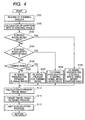
- the steering angle ⁇ detected by the steering sensor 18 is read at step S101. Subsequently, the variation of the steering angle per unit time ⁇ is calculated on the basis of the present steering angle ⁇ p and the previous steering angle ⁇ o. Next, it is determined at step S103 whether or not the steering wheel 17 is being moved back at a rate faster than a predetermined value. More specifically, it is determined whether or not the steering angle variation ⁇ is negative and an absolute value thereof is larger than a predetermined value. If it is determined at step S103 that the steering wheel 17 is not being moved back at a rate faster than the predetermined value, then the process goes to step S104 to determine whether or not the steering wheel 17 is being moved farther away at a rate faster than a predetermined value. More specifically, it is determined whether or not the steering angle variation ⁇ is positive and its value is larger than a predetermined value.
- step S104 If it is determined at step S104 that the steering wheel 17 is not being moved farther away at a rate faster than the predetermined value, then the process goes to step S105 to determine whether or not the steering angle ⁇ read at step S105 is within any one of turning ranges each of which is more than +10 or -10 degrees distant from the neutral angular position (0 degrees).
- step S105 If it is determined at step S105 that the steering angle ⁇ is not within the turning ranges, then the process goes to step S106 to generate the filtered steering angle ⁇ F by subjecting the steering angle ⁇ to a strong filtering process using a strong filter, assuming that the steering angle is within a straight running range around the neutral angular position. On the other hand, if it is determined at step S105 that the steering angle ⁇ is within one of the turning ranges, then the process goes to step S107 to generate the filtered steering angle ⁇ F by subjecting the steering angle ⁇ to a weak filtering process using a weak filter.
- step S104 If it is determined at step S104 that the steering wheel 17 is being moved farther away at a rate faster than the predetermined value (+ ⁇ in Fig. 5), then the process goes to step S108 where the steering angle ⁇ is subjected to a weak filtering process using a weak filter whose filtering strength may be the same as, or 70% or less of that of the weak filter used at step 107 in order to generate the filtered steering angle ⁇ F.
- step S103 determines the steering wheel 17 is being moved back at a rate faster than the predetermined value (- ⁇ in Fig.
- step S109 the steering angle ⁇ is subjected to a weak filtering process using a weak filter whose filtering strength may be the same as, or 70% or less of that of the weak filter used at step 107 in order to generate the filtered steering angle ⁇ F.
- the filtering strengths of the filters used at steps S106, 107, 108 and 109 are represented as F-straight, F-turn, F-farther, and F-back, respectively, they are preferably in a relationship of F-straight > F-turn > F-farther > F-back. However, they may be the same.
- step S110 calculates the primary swivel angles SWC on the basis of the filtered steering angle ⁇ F.
- a target swivel angle filtering process hereinafter described is executed at step S111.
- step S112 causes the actuators 11L or 11R to adjust the light axis of the headlight 10L or 10R on the basis of the target swivel angle SWT generated at step S111 to complete the swivel control routine.
- the actual swivel angle SWP or the direction of the light axis of the headlight 10L or 10R after being adjusted by the actuator 11L or 11R at step S112 affects the target swivel angle filtering process performed next time at step S111.
- the above-described steps S102 to S109 correspond to the steering-angle-filter selecting process P1 and the steering angle filtering process P2 shown in Fig. 3.
- Fig. 7 shows a case where the control delays when the steering wheel is being moved back and when the steering wheel is being moved farther away are considered in the target-swivel-angle-filter selecting process P4 and the target angle filtering process P5.
- Fig. 8 shows a case where the control delays when the steering wheel is being moved back and when the steering wheel is being moved farther away are not considered in the target-swivel-angle-filter selecting process P4 and the target angle filtering process P5.
- step S202 If it is determined that the above condition is not satisfied, that is, if it is determined at step S202 that there exists no significant control delay when the steering wheel is being moved back (referred to as “move-back-control delay” hereinafter), then it is determined whether or not the condition that calculated control delay is positive and the value thereof is larger than a predetermined value is satisfied.
- step S203 If it is determined that the above condition is not satisfied, that is, if it is determined at step S203 that there exists no move-back-control delay nor any significant control delay when the steering wheel is being moved farther away (referred to as "move-farther-away-control delay" hereinafter) , then the process goes to step S204 to perform the normal filtering process to complete the target-swivel-angle-filter selecting process P4 and the target angle filtering process P5.
- step S203 determines whether there exists any move-farther-away-control delay. If it is determined that the above condition is satisfied, that is, if it is determined at step S203 that there exists any move-farther-away-control delay, then the process goes to step S205 where an acceleration filtering process for reducing the move-farther-away-control delay is performed to complete the target-swivel-angle-filter selecting process P4 and the target swivel angle filtering process P5.
- the filtering strength of the filter used in this acceleration filtering process for dealing with the move-farther-away-control delay is weak, or it may be zero. In consequence, it becomes possible for the actual swivel angle SWP to follow well the primary swivel angle SWC when the steering wheel is being moved farther away as apparent by comparing Fig. 7 with Fig. 8.
- step S202 If it is determined at step S202 that the above condition is satisfied, that is, if it is determined that there exists any move-back-control delay, then the process goes to step S206 where an acceleration filtering process for reducing the move-back-control delay is performed to complete the target-swivel-angle-filter selecting process P4 and the target swivel angle filtering process P5.
- the filtering strength of the filter used in this acceleration filtering process for dealing with the move-back-control delay is weak, or it may be zero. In consequence, it becomes possible for the actual swivel angle SWP to follow well the primary swivel angle SWC when the steering wheel is being moved back as apparent by comparing Fig. 7 with Fig. 8.
- filtering strengths of the filters used at steps S204, S205, and S206 are represented as F-204, F-S205, and FS206, respectively, they are preferably in a relationship of F-S204 > F-S205 > F-S206. However, they may be the same.
- the apparatus for automatically adjusting a direction of a light axis of a vehicle headlight includes:
- the swivel control unit has a first filtering unit (P1, P2) subjecting the steering angle ⁇ detected by the steering angle sensor (18) to a first filtering process (S106) when the steering angle is within the straight running range around the neutral angular position of the steering wheel (17) and to a second filtering process (S107) whose filtering strength is weaker than the filtering strength of the first filtering process (S106) when the steering angle ⁇ is within one of turning ranges which interpose therebetween the straight running range.
- P1, P2 subjecting the steering angle ⁇ detected by the steering angle sensor (18) to a first filtering process (S106) when the steering angle is within the straight running range around the neutral angular position of the steering wheel (17) and to a second filtering process (S107) whose filtering strength is weaker than the filtering strength of the first filtering process (S106) when the steering angle ⁇ is within one of turning ranges which interpose therebetween the straight running range.
- the strong filter is selected when the steering angle is within the straight running range within which the vehicle is assumed to be running straight
- the weak filter is selected when the steering angle is within any one of the turning ranges within which the vehicle is assumed to be turning left or right.
- the filtered steering angle ⁇ F is used so that the sensitivity or responsiveness of the swivel control can be changed depending on the movement of the steering wheel. In consequence, it becomes possible to reduce disturbances in the swivel control due to the road irregularities such as wheel ruts when the vehicle is running straight, and to reduce the control delay when the vehicle is turning.
- the filtering strength of the filter used when the steering angle is within the straight running range is twice or more (preferably, four times or more) that of the filter used when the steering angle is within any one of the turning ranges. In consequence, it becomes possible to suppress unnecessary movements of the light axes of the headlights when the vehicle is running straight, that is, when the steering angle is within the straight running range.
- the first filtering unit (P1, P2) subjects the steering angle ⁇ to a third filtering process (S108) having a filtering strength which is equal to, or is 70%, or less of that of the filtering process of the second filtering process (S107) upon detecting that the steering wheel (17) is being moved farther away at a rate faster than a predetermined value.
- a third filtering process (S108) having a filtering strength which is equal to, or is 70%, or less of that of the filtering process of the second filtering process (S107) upon detecting that the steering wheel (17) is being moved farther away at a rate faster than a predetermined value.
- the first filtering unit (P1, P2) subjects the steering angle ⁇ to a fourth filtering process (S109) having a filtering strength which is equal to, or is 70%, or less of that of the third filtering process (S108) upon detecting that a steering wheel (17) is being moved back at a rate faster than a predetermined value. Accordingly, when the steering wheel is moved back rapidly; the filtering strength is made even weaker than when the steering angle is moved farther away to make a steep turn.
- the swivel control unit has also a second filtering unit (P4, P5) for filtering the primary swivel angle SWC calculated from the filtered steering angle ⁇ F to generate the target swivel angle SWT, the second filtering unit (P4, P5) varying the filtering strength thereof depending on the difference between the primary swivel angle SWC and the actual swivel angle SWT corresponding to the current direction of the light axis of the vehicle headlight.
- P4 P5 for filtering the primary swivel angle SWC calculated from the filtered steering angle ⁇ F to generate the target swivel angle SWT
- the second filtering unit (P4, P5) varying the filtering strength thereof depending on the difference between the primary swivel angle SWC and the actual swivel angle SWT corresponding to the current direction of the light axis of the vehicle headlight.
- This second filtering unit (P4, P5) makes it possible to reduce the control delay, so that the directions of the light axes of the headlights can well follow the movements of the steering wheel while the vehicle is turning.
- the second filtering unit (P4, P5) of the swivel control unit constituted by the ECU 20 and the actuators 11L, 11R is configured to make a difference in the filtering strength between when the steering wheel is being moved farther away and when the steering wheel is being moved back.
- the filtering strength when the steering wheel is being moved back is weaker than when the steering wheel is being moved farther away.
- the filter used for the steering angle filtering process P2 or the target swivel angle filtering process P5 may be a filter whose input-output characteristics is represented by the following equation.
- Fout c x Fin + (1-c) x Fold
- Fout is the output from the filter
- c is a filtering factor (0 ⁇ c ⁇ 1)
- Fin is the input to the filter
- Fold is the previous output from the filter at the previous filtering process.
- the filtering strength can be defined as (1-c) ⁇ 100 (%).
Landscapes
- Engineering & Computer Science (AREA)
- Mechanical Engineering (AREA)
- Lighting Device Outwards From Vehicle And Optical Signal (AREA)
Applications Claiming Priority (2)
| Application Number | Priority Date | Filing Date | Title |
|---|---|---|---|
| JP2003352606A JP4353764B2 (ja) | 2003-10-10 | 2003-10-10 | 車両用前照灯光軸方向自動調整装置 |
| JP2003352606 | 2003-10-10 |
Publications (3)
| Publication Number | Publication Date |
|---|---|
| EP1522456A2 true EP1522456A2 (de) | 2005-04-13 |
| EP1522456A3 EP1522456A3 (de) | 2006-03-29 |
| EP1522456B1 EP1522456B1 (de) | 2007-09-26 |
Family
ID=34309295
Family Applications (1)
| Application Number | Title | Priority Date | Filing Date |
|---|---|---|---|
| EP04024096A Expired - Lifetime EP1522456B1 (de) | 2003-10-10 | 2004-10-08 | Vorrichtung zur automatischen Einstellung der Richtung einer optischen Achse eines Autoscheinwerfers |
Country Status (4)
| Country | Link |
|---|---|
| US (1) | US20050080534A1 (de) |
| EP (1) | EP1522456B1 (de) |
| JP (1) | JP4353764B2 (de) |
| DE (1) | DE602004009139T2 (de) |
Families Citing this family (6)
| Publication number | Priority date | Publication date | Assignee | Title |
|---|---|---|---|---|
| JP4501888B2 (ja) * | 2005-07-07 | 2010-07-14 | 株式会社デンソー | 車両用前照灯装置 |
| JP4715678B2 (ja) * | 2005-08-26 | 2011-07-06 | 日産自動車株式会社 | 前照灯の光軸制御装置およびその制御方法 |
| EP1757486B1 (de) * | 2005-08-26 | 2014-04-30 | Nissan Motor Co., Ltd. | Vorrichtung und Verfahren zur Steuerung von Scheinwerfern |
| JP4838213B2 (ja) * | 2007-08-27 | 2011-12-14 | 株式会社小糸製作所 | ランプシステム及びランプ偏向制御方法 |
| JP5210104B2 (ja) | 2008-09-26 | 2013-06-12 | 株式会社小糸製作所 | ランプ偏向制御装置とランプ偏向制御方法 |
| DE102017211141A1 (de) * | 2017-06-30 | 2019-01-03 | Osram Gmbh | Effektleuchte, leuchtengruppe, anordnung und verfahren |
Citations (5)
| Publication number | Priority date | Publication date | Assignee | Title |
|---|---|---|---|---|
| US5588733A (en) * | 1995-01-17 | 1996-12-31 | Honda Giken Kogyo Kabushiki Kaisha | Head lamp device for vehicle |
| US5931572A (en) * | 1996-05-20 | 1999-08-03 | Honda Giken Kogyo Kabushiki Kaisha | Head lamp device for vehicle |
| US20030055548A1 (en) * | 2001-08-31 | 2003-03-20 | Yasutoshi Horii | Vehicle headlamp's optical axis control system |
| US20030067762A1 (en) * | 2001-10-04 | 2003-04-10 | Koito Manufacturing Co., Ltd. | Vehicle light apparatus |
| US20030114974A1 (en) * | 2001-10-31 | 2003-06-19 | Smith James E. | Automatic directional control system for vehicle headlights |
Family Cites Families (4)
| Publication number | Priority date | Publication date | Assignee | Title |
|---|---|---|---|---|
| EP0411544A3 (en) * | 1989-07-31 | 1991-08-07 | Stanley Electric Co., Ltd. | Apparatus for adjusting attitude of optical axes of head lamps on vehicle |
| JP3095971B2 (ja) * | 1995-02-07 | 2000-10-10 | 本田技研工業株式会社 | 車両用前照灯装置 |
| JP3128611B2 (ja) * | 1996-04-26 | 2001-01-29 | 株式会社小糸製作所 | 車輌用灯具の照射方向制御装置 |
| JP4087201B2 (ja) * | 2002-09-20 | 2008-05-21 | 株式会社小糸製作所 | 車両用前照灯装置の光軸位置設定方法 |
-
2003
- 2003-10-10 JP JP2003352606A patent/JP4353764B2/ja not_active Expired - Fee Related
-
2004
- 2004-10-08 US US10/959,962 patent/US20050080534A1/en not_active Abandoned
- 2004-10-08 DE DE602004009139T patent/DE602004009139T2/de not_active Expired - Lifetime
- 2004-10-08 EP EP04024096A patent/EP1522456B1/de not_active Expired - Lifetime
Patent Citations (5)
| Publication number | Priority date | Publication date | Assignee | Title |
|---|---|---|---|---|
| US5588733A (en) * | 1995-01-17 | 1996-12-31 | Honda Giken Kogyo Kabushiki Kaisha | Head lamp device for vehicle |
| US5931572A (en) * | 1996-05-20 | 1999-08-03 | Honda Giken Kogyo Kabushiki Kaisha | Head lamp device for vehicle |
| US20030055548A1 (en) * | 2001-08-31 | 2003-03-20 | Yasutoshi Horii | Vehicle headlamp's optical axis control system |
| US20030067762A1 (en) * | 2001-10-04 | 2003-04-10 | Koito Manufacturing Co., Ltd. | Vehicle light apparatus |
| US20030114974A1 (en) * | 2001-10-31 | 2003-06-19 | Smith James E. | Automatic directional control system for vehicle headlights |
Also Published As
| Publication number | Publication date |
|---|---|
| EP1522456B1 (de) | 2007-09-26 |
| JP4353764B2 (ja) | 2009-10-28 |
| JP2005112296A (ja) | 2005-04-28 |
| EP1522456A3 (de) | 2006-03-29 |
| US20050080534A1 (en) | 2005-04-14 |
| DE602004009139T2 (de) | 2008-06-26 |
| DE602004009139D1 (de) | 2007-11-08 |
Similar Documents
| Publication | Publication Date | Title |
|---|---|---|
| US6625529B2 (en) | Apparatus for controlling steering angles of front rear wheels of vehicle | |
| US20070198162A1 (en) | Preceding-vehicle following control system | |
| US7118238B2 (en) | Apparatus for automatically adjusting direction of light axis of vehicle headlight | |
| JP2002104065A (ja) | 車両用前照灯光軸方向自動調整装置 | |
| US10850740B2 (en) | Driving assistance method and driving assistance device | |
| US20120123655A1 (en) | Vehicle operation device | |
| JP2003072460A (ja) | 車両用前照灯光軸方向自動調整装置 | |
| JP4457754B2 (ja) | 車両用前照灯光軸方向自動調整装置 | |
| JP4424102B2 (ja) | 車両用前照灯光軸方向自動調整装置 | |
| US6671640B2 (en) | Automatic optical-axis adjusting device for automatically adjusting directions of optical axes of front lights with respect to steering angle of steering wheel | |
| US7246021B2 (en) | Automatic front light optical axis direction adjusting system for vehicles | |
| US7503677B2 (en) | Headlight control apparatus and method for vehicle | |
| EP1522456A2 (de) | Vorrichtung zur automatischen Einstellung der Richtung einer optischen Achse eines Autoscheinwerfers | |
| JP4593034B2 (ja) | 車両用前照灯光軸方向自動調整装置 | |
| CN116215653A (zh) | 用于在从直线行驶的转向期间控制主动式后桥转向装置的方法和控制电路及机动车 | |
| JP4353768B2 (ja) | 車両用前照灯光軸方向自動調整装置 | |
| US7239951B2 (en) | Apparatus for automatically adjusting direction of light axis of vehicle headlight | |
| US20060087856A1 (en) | Optical axis controller | |
| JP2009046063A (ja) | ランプシステム及びランプ偏向制御方法 | |
| US7131741B2 (en) | Automatic beam-axis adjustment system for vehicular headlights | |
| JP3910033B2 (ja) | 車両用前照灯光軸方向自動調整装置 | |
| JP4168920B2 (ja) | 車両用前照灯光軸方向自動調整装置 | |
| JP2005193866A (ja) | 車両用前照灯光軸方向自動調整装置 | |
| JP2004322683A (ja) | 車両用前照灯光軸方向自動調整装置 |
Legal Events
| Date | Code | Title | Description |
|---|---|---|---|
| PUAI | Public reference made under article 153(3) epc to a published international application that has entered the european phase |
Free format text: ORIGINAL CODE: 0009012 |
|
| AK | Designated contracting states |
Kind code of ref document: A2 Designated state(s): AT BE BG CH CY CZ DE DK EE ES FI FR GB GR HU IE IT LI LU MC NL PL PT RO SE SI SK TR |
|
| AX | Request for extension of the european patent |
Extension state: AL HR LT LV MK |
|
| PUAL | Search report despatched |
Free format text: ORIGINAL CODE: 0009013 |
|
| AK | Designated contracting states |
Kind code of ref document: A3 Designated state(s): AT BE BG CH CY CZ DE DK EE ES FI FR GB GR HU IE IT LI LU MC NL PL PT RO SE SI SK TR |
|
| AX | Request for extension of the european patent |
Extension state: AL HR LT LV MK |
|
| 17P | Request for examination filed |
Effective date: 20060609 |
|
| 17Q | First examination report despatched |
Effective date: 20060727 |
|
| AKX | Designation fees paid |
Designated state(s): DE FR GB |
|
| GRAP | Despatch of communication of intention to grant a patent |
Free format text: ORIGINAL CODE: EPIDOSNIGR1 |
|
| GRAS | Grant fee paid |
Free format text: ORIGINAL CODE: EPIDOSNIGR3 |
|
| GRAA | (expected) grant |
Free format text: ORIGINAL CODE: 0009210 |
|
| AK | Designated contracting states |
Kind code of ref document: B1 Designated state(s): DE FR GB |
|
| REG | Reference to a national code |
Ref country code: GB Ref legal event code: FG4D |
|
| RIN1 | Information on inventor provided before grant (corrected) |
Inventor name: NISHIMURA, KENICHIC/O DENSO CORPORATION |
|
| REF | Corresponds to: |
Ref document number: 602004009139 Country of ref document: DE Date of ref document: 20071108 Kind code of ref document: P |
|
| PLBE | No opposition filed within time limit |
Free format text: ORIGINAL CODE: 0009261 |
|
| STAA | Information on the status of an ep patent application or granted ep patent |
Free format text: STATUS: NO OPPOSITION FILED WITHIN TIME LIMIT |
|
| 26N | No opposition filed |
Effective date: 20080627 |
|
| PGFP | Annual fee paid to national office [announced via postgrant information from national office to epo] |
Ref country code: DE Payment date: 20091001 Year of fee payment: 6 |
|
| PGFP | Annual fee paid to national office [announced via postgrant information from national office to epo] |
Ref country code: FR Payment date: 20091029 Year of fee payment: 6 Ref country code: GB Payment date: 20091007 Year of fee payment: 6 |
|
| GBPC | Gb: european patent ceased through non-payment of renewal fee |
Effective date: 20101008 |
|
| PG25 | Lapsed in a contracting state [announced via postgrant information from national office to epo] |
Ref country code: FR Free format text: LAPSE BECAUSE OF NON-PAYMENT OF DUE FEES Effective date: 20101102 |
|
| REG | Reference to a national code |
Ref country code: FR Ref legal event code: ST Effective date: 20110630 |
|
| PG25 | Lapsed in a contracting state [announced via postgrant information from national office to epo] |
Ref country code: GB Free format text: LAPSE BECAUSE OF NON-PAYMENT OF DUE FEES Effective date: 20101008 |
|
| REG | Reference to a national code |
Ref country code: DE Ref legal event code: R119 Ref document number: 602004009139 Country of ref document: DE Effective date: 20110502 |
|
| PG25 | Lapsed in a contracting state [announced via postgrant information from national office to epo] |
Ref country code: DE Free format text: LAPSE BECAUSE OF NON-PAYMENT OF DUE FEES Effective date: 20110502 |