EP1520956B1 - Tapis avec un tiroir et/ou un conduit pour une barre - Google Patents
Tapis avec un tiroir et/ou un conduit pour une barre Download PDFInfo
- Publication number
- EP1520956B1 EP1520956B1 EP04021466A EP04021466A EP1520956B1 EP 1520956 B1 EP1520956 B1 EP 1520956B1 EP 04021466 A EP04021466 A EP 04021466A EP 04021466 A EP04021466 A EP 04021466A EP 1520956 B1 EP1520956 B1 EP 1520956B1
- Authority
- EP
- European Patent Office
- Prior art keywords
- mat according
- channels
- rolling
- rolling mat
- insert
- Prior art date
- Legal status (The legal status is an assumption and is not a legal conclusion. Google has not performed a legal analysis and makes no representation as to the accuracy of the status listed.)
- Expired - Lifetime
Links
- 238000003780 insertion Methods 0.000 claims description 65
- 230000037431 insertion Effects 0.000 claims description 65
- 238000005096 rolling process Methods 0.000 claims description 61
- 238000005065 mining Methods 0.000 claims description 12
- 239000002184 metal Substances 0.000 claims description 8
- 238000004519 manufacturing process Methods 0.000 claims description 7
- 239000000463 material Substances 0.000 claims description 3
- 238000000034 method Methods 0.000 claims description 3
- 238000009941 weaving Methods 0.000 claims description 3
- 229920002994 synthetic fiber Polymers 0.000 claims 3
- 238000005259 measurement Methods 0.000 claims 1
- 230000000979 retarding effect Effects 0.000 claims 1
- 239000004033 plastic Substances 0.000 abstract description 40
- 230000004308 accommodation Effects 0.000 abstract 1
- 239000004744 fabric Substances 0.000 description 38
- 239000000835 fiber Substances 0.000 description 9
- 230000005641 tunneling Effects 0.000 description 8
- 239000004566 building material Substances 0.000 description 7
- 238000010276 construction Methods 0.000 description 7
- RNFJDJUURJAICM-UHFFFAOYSA-N 2,2,4,4,6,6-hexaphenoxy-1,3,5-triaza-2$l^{5},4$l^{5},6$l^{5}-triphosphacyclohexa-1,3,5-triene Chemical compound N=1P(OC=2C=CC=CC=2)(OC=2C=CC=CC=2)=NP(OC=2C=CC=CC=2)(OC=2C=CC=CC=2)=NP=1(OC=1C=CC=CC=1)OC1=CC=CC=C1 RNFJDJUURJAICM-UHFFFAOYSA-N 0.000 description 4
- 238000013461 design Methods 0.000 description 4
- 239000003063 flame retardant Substances 0.000 description 4
- 238000009958 sewing Methods 0.000 description 4
- 230000000694 effects Effects 0.000 description 3
- 238000005192 partition Methods 0.000 description 2
- 238000012549 training Methods 0.000 description 2
- 238000009825 accumulation Methods 0.000 description 1
- 239000000654 additive Substances 0.000 description 1
- 230000000996 additive effect Effects 0.000 description 1
- 239000002216 antistatic agent Substances 0.000 description 1
- 238000009412 basement excavation Methods 0.000 description 1
- 230000033228 biological regulation Effects 0.000 description 1
- 238000006243 chemical reaction Methods 0.000 description 1
- 239000002131 composite material Substances 0.000 description 1
- 150000001875 compounds Chemical class 0.000 description 1
- 239000004567 concrete Substances 0.000 description 1
- 238000005260 corrosion Methods 0.000 description 1
- 230000007797 corrosion Effects 0.000 description 1
- 238000004880 explosion Methods 0.000 description 1
- 239000011152 fibreglass Substances 0.000 description 1
- 230000010354 integration Effects 0.000 description 1
- 229930014626 natural product Natural products 0.000 description 1
- 238000012545 processing Methods 0.000 description 1
- 230000035939 shock Effects 0.000 description 1
- 238000002791 soaking Methods 0.000 description 1
- 230000006641 stabilisation Effects 0.000 description 1
- 238000011105 stabilization Methods 0.000 description 1
- 239000013589 supplement Substances 0.000 description 1
- 239000003643 water by type Substances 0.000 description 1
Images

Classifications
-
- E—FIXED CONSTRUCTIONS
- E21—EARTH OR ROCK DRILLING; MINING
- E21D—SHAFTS; TUNNELS; GALLERIES; LARGE UNDERGROUND CHAMBERS
- E21D11/00—Lining tunnels, galleries or other underground cavities, e.g. large underground chambers; Linings therefor; Making such linings in situ, e.g. by assembling
- E21D11/14—Lining predominantly with metal
- E21D11/15—Plate linings; Laggings, i.e. linings designed for holding back formation material or for transmitting the load to main supporting members
- E21D11/152—Laggings made of grids or nettings
Definitions
- the invention relates to a rolling mat of intersecting thread systems with chain and weft of PP plastic, especially plastic fibers, plastic strips or plastic threads, which is used for the production of lining sheets for underground mining and tunneling and rod-shaped support rods having.
- the invention is therefore an object of the invention to provide a rolling mat, which is easy to transport and yet secured against large bulges and in particular to use in underground mining and tunneling with its special protection regulations.
- the object is achieved according to the invention in that running in the weft insertion slots are provided in a predetermined intervals are integrated with each other during the weaving process in the thread systems, which have an insertion of a support rod diameter enabling and formed by the chain and weft plastic strips formed over the entire width of the mat continuous, a support rod enclosing tube are executed.
- This possibility is given to comply exactly with the predetermined distances in such rolling mats or fabrics, on the other hand, but also to vary, if this proves useful in use.
- the Rollmatten nachzuarrin will then have correspondingly different distances.
- the support rods can basically be inserted arbitrarily at any time, even if they are usually already inserted at the manufacturer in the factory.
- the effective distance between two adjacent support rods can thus be varied to a corresponding extent.
- the manufacturer has the ability to form the runway or rolling mat, as the customer just wants to change the distances with support bars so practically.
- a further advantage is that the predetermined insertion channels do not affect the outer surface or better said the surface of the fabric when not in use, on the other hand occur with inserted support rods, the resulting bulges on both sides, so that an excessive change of the in itself flat mat does not occur.
- the support rods or the other dimensions can be used without great effort, depending on how the customer wishes and if necessary, it is even possible to exchange the support rods on site. An always secure and secured against falling out seat of the support rods within the roll mat is always given.
- the insertion channels as such are indicated by the fact that here a "accumulation" of plastic bands, fibers or threads is present, so that even without the separate label the necessary assembly aid is always present.
- the slide-in channels described can be realized simply and reliably by the fact that in the region of the slide-in channels the weft belonging to the thread system is doubled in succession, ie has a front and a rear weft element.
- the respective support bar is thus pushed between these weft elements or better said these successive shots, safely bordered and secured by these, so that then the support rod reaches the optimum position within the rolling mat.
- the shots are connected via the chains, which will be explained later. This results exactly in the given area in each case a slide-in channel, which is securely marked and receives all around a wall that not only facilitates the insertion of the support rod, but at the same time also ensures that he gets a safe position after insertion.
- such a slide-in channel is predetermined only at a predetermined distance and range, which, as mentioned earlier, can be exploited by inserting a support rod or not even if such a support rod in this area is not necessary or should not be inserted for other reasons .
- these insertion channels can also be used, for example, for passing cables, ropes or the like, if the described fabrics or rolling mats, for example, should have only limited rigidity or even be flexible, namely at right angles to the longitudinal direction of the web. In particular, when ropes or ropes are inserted, a folding of such a fabric or a roll mat is easily possible and thus an even better transport.
- the invention provides that the distances of the insertion channels 10 to 50 cm, preferably 15 cm, have. Even with this small distance of 10 to 15 cm, such a mat can easily be rolled up or pushed together, so as to keep the dimensions for transport within limits. The distance depends, as already mentioned, on the particular application and in particular the expected pressures to which this tissue is to oppose the necessary support forces. The greater the pressure, the lower the distance of the individual support rods must be, depending on the design of these insertion channels support rods of different diameters can be used, ie round, square or rectangular but also support bars.
- the Rollmatte described absorbs the necessary forces safely, if the chains of narrow plastic ribbon and the shots with the exception of the slide-in channels of the same narrow plastic ribbon, in the range of insertion channels but are formed by wide plastic ribbon.
- These wider plastic tapes in the field of insertion channels take into account once the need for the support bars must be securely bordered and guided and on the other hand, that here a close concern is also guaranteed and beyond the position of the respective insertion channel are characterized by the ribbon can.
- the described design of the rolling mat is particularly sufficient by just in the field of insertion channels wider plastic tapes are used.
- the narrow plastic strips are designed to have a width of 0.8 to 1.2 mm and the wide plastic ribbon of 1.75 to 5 mm.
- This wider version of the plastic ribbon also has the advantage that they can be injected better when weaving or making the rolling mat.
- the wide plastic tapes give In this case, the insertion channel not only the necessary smoothest possible wall before, but can, as already mentioned, also process well.
- the wide or broader Kunststofftoff tapes in the field of insertion channels have the advantages described further above, and these can be further increased by the fact that the wide plastic tapes are designed as a plastic multifilament.
- These plastic multifilaments offer the insertion channel not only an even greater strength, smoother wall and better identifiability, but they also have a visually advantageous effect, because they give the respective position of the insertion channels even more optimal, it being particularly advantageous if five to ten wider front and rear plastic ribbons forming a drawer channel are arranged.
- the insertion channels should have a width that allows the user or manufacturer to introduce the optimal sized support rods. It has been found that it is generally advantageous and expedient that the insertion channels have a width of 2.0 to 4 cm, preferably of 2.5 cm. In such a design, it is possible, as already mentioned, possible to introduce support rods with a round cross-section, with square cross-section but also with a rectangular cross-section, these rectangular cross-sections ultimately so dimensioned or provided for support rods may be such that it is are virtually sheets that still give the fabric a certain rigidity. It should also be mentioned that these slide-in channels offer the possibility of cords, tapes or the like if this should be recognized as appropriate or proves to be advantageous for the particular application.
- the front or the rear shot elements are designed as metal or plastic wire, because they support the action of the support rods and because if necessary, the insertion of the support rods can be facilitated.
- metal wires in particular would have the advantage that they support the effect of the support rods in the discharge, with both metal and plastic wires have the advantage of facilitating shooting because the weft elements have a certain inherent rigidity.
- the front and / or the rear weft elements are formed as plastic-coated metal wire.
- This plastic coated metal wire has a certain inherent rigidity and is therefore good to use as a shot element.
- the insertion of the support rods in the created insertion channels is specifically facilitated by the fact that according to the invention, the support rods on one or both sides have rounded ends or are equipped with a slide-in the insertion channels facilitating cap. Since the support rods are inserted by hand usually, especially the beginning of this insertion work is facilitated, because it facilitates the finding of the channel, which of course also applies when a mechanical insertion device is created, which can also work cheaper and safer, when the support rods are formed accordingly.
- the thread systems are formed by electrically non-conductive elements and electrically conductive elements, wherein the non-conductive elements are provided with a permanently flame-retardant additive and the electrically conductive are used only as a chain. This results in a fabric that consistently flame-retardant or flame retardant, as well as antistatic, so that even in problematic rooms, the use of this fabric or the rolling mat is no obstacle.
- the electrically conductive elements are designed as metal-damped multifilaments, because then the antistatic materials can be particularly easily integrated into the multifilaments.
- Multifilaments are, as mentioned earlier, yes for the presentation of the slide-in channels of advantage. They can also be used as a chain, which would ultimately meet the strength or sustainability of the rolling mat yet.
- the electrically conductive elements In order to use the electrically conductive elements as possible only in one direction, it is expedient to arrange the electrically conductive elements at a distance of 3 cm or less to each other, and as mentioned, to use as a chain. At such a small distance, it is sufficient to achieve the antistatic, if these electrically conductive, but also more expensive from the production elements are used only as a chain.
- the used supporting rods are inserted into the insertion channels and then the entire rolling mat is pushed together or rolled up brought to the place of use.
- the invention provides that the support rods are designed to be fixable on Einschubbegrenzer in the retracted position. These slide-in limiters can be postponed as a rule after insertion onto the support rod or attached to it, so as to prevent falling out of the rolling mat.
- the insertion limiter is releasably connected to the support rod, which is provided according to an advantageous embodiment of the innovation that the Einschubbeskyr are designed as cable ties, easily in retrospect on the respective support rod end are to be fastened so as to effectively prevent falling out.
- pocket-shaped rod channels are provided between the woven insertion channels by folding the mat and pulling a demarcation seam to a darts, in which the support rods are inserted if necessary.
- the rod channels are introduced after completion of the mat by making the dart in the mat. It can also be made possible by this special design of the rod channels that additionally particularly thicker in diameter support rods are used as a supplement, if the circumstances require it, while the other insertion channels accommodate support rods with a smaller diameter. Especially this Diameter larger rod channels would be worse to produce in a roll mat only with integrated insertion channels, because in each case the conversion of the entire loom is necessary, while in the proposed solution after the completion of the actual mat until the corresponding rod channels are made and then virtually any dimension without big problems can be given.
- the invention provides that in the insertion channels, in each case a projection is reached or predetermined on both sides over the mat surface, while in the rod channels the enclosed support rods with the respective rod channel material protrude to a mat side.
- the invention provides that the bar channels are formed above each on the same side of the mat above, so as to allow integration into the post-filled building material.
- insertion limiters or other aids are placed on the individual support rods in order to prevent them from slipping out of the insertion channel or the rod channel.
- the dart resulting a rod channel unilaterally formed a closure forming and thus the rod channel is formed on this side occlusive. A corresponding backup is then necessary on one side, which facilitates the entire work.
- an extension of the diameter of the channel is achieved by pulling up or bring up the darts, so that the inserted support rod can also be stuck here, so it does not require a corresponding anti-skid device.
- the invention In order to make the position of the insertion channels or the rod channels visually easier to recognize when inserting the support rods in retrospect, the invention also provides that the weft elements or darts are highlighted in color over the rest of the mat material. As a result, without great problems in retrospect, a support rod at any time be inserted in such a way that this results in the optimum stability of the entire roll mat.
- the invention is characterized in particular by the fact that a rolling mat is created, which is easy to transport due to the low weight, but which can also be easily rolled up and pushed together, so has little space and thus can be easily transported.
- This rolling mat is very stable by the insertion of the support rods and can withstand and absorb large pressures without causing any significant deformations.
- this fabric tracks or rolling mats in mining and tunneling but also in the construction sector and then fill in, for example, concrete or building material behind, so as to specify a stable wall, for example, a pit or the shocks or ridges hedges.
- such a roll mat in particular made of PP fabric can be used very safely, because there is the possibility to ensure the necessary antistatic and flame retardant effect or the rolling mat to specify this.
- a further advantage is that such a roll mat are completely equipped both in the factory with support rods or only partially, in which case support rods are there in retrospect still arranged or integrated, where it proves necessary.
- the insertion channels described are supplemented by bar channels, which are arranged between them and arise by folding and producing a Ab committeers and thus give the opportunity to optimize the additional fixation in the building material, which is especially true when this rolling mat used by rolling off the expansion becomes.
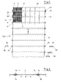
- FIG. 1 shows a fabric 1 for a roll mat 13 in the form of a web, which consists of a crossing thread system 2, 6.
- plastic bands 3 which are used both for the chain 4 as for the shot 5 use.
- the thread system 2, 6 with chain 4 and shot 5 is designed so that at intervals 8 insertion channels 7, 9 are realized in the support rods 10, 11 can be inserted.
- the insertion of the support rods 10, 11 takes place in the weft direction 12th
- Such fabric sheets 1 / Rollmatten 13 are, as the other figures show, used to cover surfaces and to introduce, for example, behind such fabric webs 1 / Rollmatten 13 building material and thus to specify a stabilized wall. Other applications and purposes are conceivable, and it is important that such a fabric web 1 / roll mat 13 is advantageously stabilized by the inserted support rods 10, 11.
- FIG. 2 shows that the support rods 10, 11 introduced at a distance of 8 from each other are inserted into insertion channels 7, 9 predetermined there.
- These insertion channels are defined by the fact that in the region of the insertion channels 7, 8 front and rear weft elements 14, 15 are arranged lying twice, wherein the front and rear weft elements 14, 15 are alternately bordered by the adjacent chains 4. Again, this is a further explanation behind.
- the inserted support rods 10, 11 are fixed according to Figure 1 by Einschubbeskyr 23, 24, in which case the Einschubbeskyr 24, 24 'are fixed so that they can be pushed up to the Einschubbeskyr 23, whereupon then the releasable Einschubbeskyr 24 is pushed and fixed ,
- the fabric 1 and the rolling mat 13 consists of electrically conductive elements 20 and electrically non-conductive elements 21.
- Dienoce conductive elements 20 are arranged at a distance from each other and are realized only as a chain 4.
- the electrically non-conductive elements 21 are used both as a chain 4 as well as a shot 5, wherein it is theoretically also conceivable that individual of the shots 5 also form as electrically conductive elements.
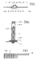
- FIG 3 shows a single support rod 10, 11 which is inserted in such a slot 7. It can be seen here that several front weft elements 14, 14 ', 14 ", 14'” and 14. 14 .. and rear weft elements 15, 15 ', 15 ", 15"' and 15., 15 .. are formed. Through this front and rear weft element 14, 15 results in the insertion channel 7, 9 predetermining channel wall. The respective front and rear weft elements 14, 15 are held together by the chain 4 in the form of a narrow plastic ribbon 3, 16, whereby this chain 4 - not clearly visible here - surrounds the respective front and rear weft elements 14, 15 and these surrounds.
- Figure 6 and Figure 7 show an application in underground mining and tunneling, in which case the fabric webs 1 are formed as delay mats or rolling mats 31, which cover the adjacent expansion bows 28, 29, 30 of the track construction 27 an underground section 26, so a safe protection against the mountains is reached, especially if then after laying the default mats 31 or the rolling of the rolling mats 31 building material between the fabric web 1 and the mountains is filled.
- Such as rolling mat 13 serving stabilized fabric 1 can be used for the purposes already mentioned, but also to specify simple partitions between two rooms, in which case advantageously the distances 8 can be increased, wherein such then realized wall of the fabric rolled or can be unrolled, depending on how it proves necessary and appropriate.
- partitions to specify a stage space or subdivide, depending on how it proves useful. So far, complex components must be used here, since they must have the necessary stability. In fabrics according to the invention, however, it is sufficient if this fabric is suspended or possibly also clamped; in any case, no inherent stability is required since the support rods 10, 11 used here provide the necessary load-bearing capacity or rigidity in the case of a clamped fabric web 1.
- Figure 1 shows a possible embodiment of the ends 33, 34 of the support rods 10, 11, via which the insertion into the insertion channels 7, 9 can be facilitated.
- a pointed or rounded tip 36 is created or it is on the end 33 and 34 of the support rod 10, 11, a cap 35 is pushed, which is designed so that so that the beginning of the insertion channel 7, 9 is easier to find.
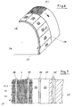
- FIG. 9 shows this roll mat 13 in section, wherein it becomes clear that these slide-in channels 7, 9 are integrated with their support rods 10, 10 ', 11, 11' in the fabric 1 or the roll mat 13 and at the same time rod channels 40, 41 with support rods 10, 11, which are arranged on the mat side 42, while the mat side 43 is formed here continuously, d. H. without any curvature.
- This particular training gives in a simple and convenient way, the possibility of even in underground use still support rods 10, 11 in retrospect to connect with the rolling mat 13, wherein the insertion of the resulting by the darts 39 bar channels 40, 41 is lighter than that Insertion of the support rods 10, 11 in the insertion channels 7, 9, which can be done largely mechanically.
- rod channels 40, 41 are exclusively provided, these each specifying a tube 19, as indeed also the insertion channels 7, 9.
- the rod channels 40, 41 are, as already mentioned, associated with a mat side 42, which is illustrated in FIG. 11, wherein the darts 39 can be seen here, too, which predefine the respective rod channels 40, 41 after the fabric web 1 has been folded.
- Figure 12 shows in the upper part of such an empty bar channel 40 into which a support rod 10 or 11, not shown here, can be inserted, wherein the corresponding tube 19 is formed across the width of the rolling mat and after the lower part of Figure 12 on the opposite side forms a closure 44, which prevents a pushing through of the support rod 10. Due to the shape of the closure 44 is then achieved at the same time that the support rod 10th fix something, because of the special high leadership of Abierrs 39 of the rod channel 40 tapers pointed.
Landscapes
- Engineering & Computer Science (AREA)
- Mining & Mineral Resources (AREA)
- General Life Sciences & Earth Sciences (AREA)
- Structural Engineering (AREA)
- Civil Engineering (AREA)
- Life Sciences & Earth Sciences (AREA)
- Architecture (AREA)
- Geochemistry & Mineralogy (AREA)
- Geology (AREA)
- Woven Fabrics (AREA)
- Mattresses And Other Support Structures For Chairs And Beds (AREA)
- Chairs Characterized By Structure (AREA)
- Treatment Of Fiber Materials (AREA)
- Biological Treatment Of Waste Water (AREA)
Claims (23)
- Tapis roulant composé de systèmes de fils (2, 6) croisés avec chaîne (4) et trame (5) synthétique en polypropylène, surtout en filaments synthétiques (6), bandelettes en matière synthétique (3) ou fils en matière synthétique, qui sert à la fabrication de voies de revêtement pour les espaces dans l'industrie minière et la construction de tunnels et qui présente des barres porteuses (10, 11) en forme de tige.
caractérisé en ce que
sont prévus des canaux d'insertion (7, 9) qui courent dans le sens de la trame (12), lesquels canaux sont intégrés dans les systèmes de fils (2, 6) pendant le tissage à une distance prédéfinie l'une par rapport à l'autre, présentant un diamètre qui permet l'introduction d'une barre porteuse (10, 11) et résultant en un tube (19) formé de bandelettes en matière synthétique (3) formant les chaînes (4) et la trame (5), tube qui traverse toute la largeur du tapis (13) et entoure une barre porteuse (10, 11). - Tapis roulant selon la revendication 1,
caractérisé en ce que
au niveau des canaux d'insertion (7, 9), la trame (5) qui appartient au système de fils (6) est formée de deux éléments couchés l'un derrière l'autre, c'est-à-dire présente un élément de trame avant et un élément de trame arrière (14, 15). - Tapis roulant selon les revendications 1 et 2,
caractérisé en ce que
au niveau des canaux d'insertion (7, 9), les chaînes (4) qui appartiennent au système de fils (2) et courent l'une à côté de l'autre sont formées et disposées de manière à ceindre alternativement les éléments de trame avant et arrière (14, 15) - Tapis roulant selon l'une quelconque ou plusieurs des revendications précédentes,
caractérisé en ce que
les écartements (8) des canaux d'insertion (7, 9) mesurent de 10 à 50 m, de préférence 15 cm. - Tapis roulant selon l'une quelconque ou plusieurs des revendications précédentes,
caractérisé en ce que
les chaînes (4) sont formées de bandelettes en matière synthétique (3, 16) minces, et les trames (5) sont formées, sauf au niveau des canaux d'insertion (7, 9), par les mêmes bandelettes en matière synthétique (3, 16) minces, et sont formées au niveau des canaux d'insertion (7, 9) par des bandelettes en matière synthétique (3, 17) larges. - Tapis roulant selon la revendication 5,
caractérisé en ce que
les bandelettes en matière synthétique (3, 16) minces ont une largeur de 0,8 à 1,2 et les bandelettes en matière synthétique (3, 17) larges une largeur de 1,75 à 5 mm. - Tapis roulant selon l'une quelconque ou plusieurs des revendications précédentes,
caractérisé en ce que
les bandelettes en matière synthétique (3, 17) larges sont formées comme multifilament en matière synthétique (18). - Tapis roulant selon l'une quelconque ou plusieurs des revendications précédentes,
caractérisé en ce que
cinq à dix éléments de trame larges avant et arrière (14, 15) sont disposés de manière à former un canal d'insertion (7, 9). - Tapis roulant selon l'une quelconque ou plusieurs des revendications précédentes,
caractérisé en ce que
les canaux d'insertion (7, 9) ont une largeur de 2,0 à 4 cm, de préférence de 2,5 cm. - Tapis roulant selon l'une quelconque ou plusieurs des revendications précédentes,
caractérisé en ce que
les éléments de trame avant et / ou les éléments de trame arrière (14, 15) sont formés comme fils métalliques ou fils en matière synthétique. - Tapis roulant selon l'une quelconque ou plusieurs des revendications précédentes,
caractérisé en ce que
les éléments de trame avant et / ou les éléments de trame arrière (14, 15) sont formés comme fils métalliques sous gaine plastique. - Tapis roulant selon l'une quelconque ou plusieurs des revendications précédentes,
caractérisé en ce que
les barres porteuses (10, 11) présentent sur un seul côté ou sur les deux côtés des extrémités arrondies (33, 34) ou sont équipées d'un capuchon (35) qui facilite l'introduction dans les canaux d'insertion (7, 9). - Tapis roulant selon l'une quelconque ou plusieurs des revendications précédentes,
caractérisé en ce que
les systèmes de fils (6) sont formés par des éléments non conducteurs de courant (21) et des éléments conducteurs de courant (20), étant donné que les éléments non conducteurs (21) sont dotés d'un additif ignifuge en permanence et que les éléments conducteurs de courant sont utilisés uniquement comme chaîne (4). - Tapis roulant selon l'une quelconque ou plusieurs des revendications précédentes,
caractérisé en ce que
les éléments conducteurs de courant (20) sont réalisés comme multifilaments métallisés sous vide. - Tapis roulant selon l'une quelconque ou plusieurs des revendications précédentes,
caractérisé en ce que
les éléments conducteurs de courant (20) sont disposés à une distance de 3 cm ou moins l'un de l'autre. - Tapis roulant selon l'une quelconque ou plusieurs des revendications précédentes,
caractérisé en ce que
les barres porteuses (10, 11) peuvent être fixées par l'intermédiaire de butées d'insertion (23, 24) à la position insérée. - Tapis roulant selon la revendication 6,
caractérisé en ce que
au moins une des butées d'insertion (24) est reliée de manière amovible avec la barre porteuse (10, 11). - Tapis roulant selon l'une quelconque ou plusieurs des revendications précédentes,
caractérisé en ce que
le ou les butées d'insertion (24, 25) sont formées comme serre-câbles. - Tapis roulant selon l'une quelconque des revendications précédentes,
caractérisé en ce que
sont prévus entre les canaux d'insertion (7, 9) tissés, par pliage du tapis (13) et passage d'une couture de délimitation à une couture-pinces (39), des canaux à barres (40, 41) en forme de poche dans lesquels les barres porteuses (10, 11) peuvent être insérées en cas de besoin. - Tapis roulant selon la revendication 19,
caractérisé en ce que
les canaux à barres (40, 41) sont, après l'achèvement du tapis (13), introduits dans le tapis (13) par réalisation des coutures-pinces (39). - Tapis roulant selon la revendication 19,
caractérisé en ce que
les canaux à barres (40, 41) sont formés de manière à déborder chaque fois du même côté de tapis (42). - Tapis roulant selon la revendication 19,
caractérisé en ce que
la coupure-pinces (39) qui forme un canal à barres (40) est conduite vers le haut de manière à former une fermeture (44) et, ainsi, le canal à barres est formé de manière à obturer. - Tapis roulant selon la revendication 1 ou la revendication 19,
caractérisé en ce que
les éléments de trame (14, 159 ou les coupures-pinces (39) ont une couleur qui les démarque des autres matériaux du tapis.
Priority Applications (1)
| Application Number | Priority Date | Filing Date | Title |
|---|---|---|---|
| PL04021466T PL1520956T3 (pl) | 2003-09-30 | 2004-09-09 | Mata rolowana z kanałami wpustowymi i/lub kanałami dla prętów |
Applications Claiming Priority (4)
| Application Number | Priority Date | Filing Date | Title |
|---|---|---|---|
| DE20315194U | 2003-09-30 | ||
| DE20315194U DE20315194U1 (de) | 2003-09-30 | 2003-09-30 | Gewebe mit Einschubkanälen |
| DE102004029669 | 2004-06-18 | ||
| DE102004029669A DE102004029669A1 (de) | 2003-09-30 | 2004-06-18 | Rollmatte mit Einschubkanälen und/oder Stabkanälen |
Publications (2)
| Publication Number | Publication Date |
|---|---|
| EP1520956A1 EP1520956A1 (fr) | 2005-04-06 |
| EP1520956B1 true EP1520956B1 (fr) | 2007-02-28 |
Family
ID=34315115
Family Applications (1)
| Application Number | Title | Priority Date | Filing Date |
|---|---|---|---|
| EP04021466A Expired - Lifetime EP1520956B1 (fr) | 2003-09-30 | 2004-09-09 | Tapis avec un tiroir et/ou un conduit pour une barre |
Country Status (3)
| Country | Link |
|---|---|
| EP (1) | EP1520956B1 (fr) |
| AT (1) | ATE355443T1 (fr) |
| PL (1) | PL1520956T3 (fr) |
Family Cites Families (6)
| Publication number | Priority date | Publication date | Assignee | Title |
|---|---|---|---|---|
| DE1169396B (de) * | 1961-09-06 | 1964-05-06 | Becker Pruente G M B H | Drahtmatte fuer den Verzug der Stoesse von Strecken oder Schaechten |
| DE1878018U (de) * | 1963-06-04 | 1963-08-22 | Becker Pruente G M B H | Drahtverzugsmatte fuer den strecken- und blindschachtausbau. |
| DE2000384B1 (de) * | 1970-01-07 | 1971-08-26 | Becker Pruente Gmbh | Gittermatte zum Verziehen von Ausbau im Bergbau |
| AT348577B (de) * | 1973-01-10 | 1979-02-26 | Weber Hans Georg Dipl Ing | Hohlraumausbautafel nach dem gitterskelettsystem |
| DE2437323C2 (de) * | 1974-08-02 | 1983-09-08 | Drahtwerke Rösler Soest GmbH & Co KG, 4770 Soest | Ausrollbare Verzugmattenbahn für den Streckenausbau im Berg- und Tunnelbau |
| DE3832355A1 (de) * | 1988-05-20 | 1989-11-30 | Schulte Klaus | Doks-verbundschiebe- und rollmatte |
-
2004
- 2004-09-09 EP EP04021466A patent/EP1520956B1/fr not_active Expired - Lifetime
- 2004-09-09 AT AT04021466T patent/ATE355443T1/de not_active IP Right Cessation
- 2004-09-09 PL PL04021466T patent/PL1520956T3/pl unknown
Also Published As
| Publication number | Publication date |
|---|---|
| EP1520956A1 (fr) | 2005-04-06 |
| PL1520956T3 (pl) | 2007-07-31 |
| ATE355443T1 (de) | 2006-03-15 |
Similar Documents
| Publication | Publication Date | Title |
|---|---|---|
| DE1012319B (de) | Als Schneezaun verwendbarer Drahtzaun | |
| DE2344178C2 (de) | Senkstück mit festem Ballast | |
| DE2949373C2 (de) | Gewebter Schlauch für den Untertagebergbau | |
| DE3919902A1 (de) | Zellenstruktur zur bodenbefestigung | |
| EP1520956B1 (fr) | Tapis avec un tiroir et/ou un conduit pour une barre | |
| DE102004029669A1 (de) | Rollmatte mit Einschubkanälen und/oder Stabkanälen | |
| DE2854579C2 (de) | Bewehrungsrollmatte | |
| AT387807B (de) | Bauelementsystem | |
| EP1584721B1 (fr) | Toile de protection à haute performance avec propriété antistatique et ignifuge | |
| CH681818A5 (fr) | ||
| DE3530125C2 (de) | Rollverzugmatte | |
| DE2540887C3 (de) | Böschungssicherung | |
| DE3915837A1 (de) | Baustoff-teleskopstempel | |
| DE29710701U1 (de) | Dauerhaft ableitfähiges Gewebe für den Untertageeinsatz | |
| DE3742407C2 (de) | Verzugmatte für den Streckenausbau | |
| DE3722183C2 (fr) | ||
| DE3208177C2 (fr) | ||
| DE3832355C2 (fr) | ||
| DE3404837A1 (de) | Vorrichtung zur verwahrung von bewehrungsstaehlen | |
| EP0566539A1 (fr) | Armature pour maçonnerie | |
| DD237369A1 (de) | Waermeuebertragungselement | |
| DE2037731C3 (de) | Anschluß des Randes einer Dachhaut an eine Ortgangverkleidung oder an ein Wandanschlußprofil | |
| DE4427147A1 (de) | Verlegbare Rohranordnung | |
| DE3815674C2 (fr) | ||
| DE8522833U1 (de) | Rollverzugmatte |
Legal Events
| Date | Code | Title | Description |
|---|---|---|---|
| PUAI | Public reference made under article 153(3) epc to a published international application that has entered the european phase |
Free format text: ORIGINAL CODE: 0009012 |
|
| 17P | Request for examination filed |
Effective date: 20050126 |
|
| AK | Designated contracting states |
Kind code of ref document: A1 Designated state(s): AT BE BG CH CY CZ DE DK EE ES FI FR GB GR HU IE IT LI LU MC NL PL PT RO SE SI SK TR |
|
| AX | Request for extension of the european patent |
Extension state: AL HR LT LV MK |
|
| 17Q | First examination report despatched |
Effective date: 20050615 |
|
| AKX | Designation fees paid |
Designated state(s): AT BE BG CH CY CZ DE DK EE ES FI FR GB GR HU IE IT LI LU MC NL PL PT RO SE SI SK TR |
|
| GRAP | Despatch of communication of intention to grant a patent |
Free format text: ORIGINAL CODE: EPIDOSNIGR1 |
|
| RIN1 | Information on inventor provided before grant (corrected) |
Inventor name: SCHULTE-WANTIA, SUSANNE |
|
| GRAS | Grant fee paid |
Free format text: ORIGINAL CODE: EPIDOSNIGR3 |
|
| GRAA | (expected) grant |
Free format text: ORIGINAL CODE: 0009210 |
|
| AK | Designated contracting states |
Kind code of ref document: B1 Designated state(s): AT BE BG CH CY CZ DE DK EE ES FI FR GB GR HU IE IT LI LU MC NL PL PT RO SE SI SK TR |
|
| PG25 | Lapsed in a contracting state [announced via postgrant information from national office to epo] |
Ref country code: DK Free format text: LAPSE BECAUSE OF FAILURE TO SUBMIT A TRANSLATION OF THE DESCRIPTION OR TO PAY THE FEE WITHIN THE PRESCRIBED TIME-LIMIT Effective date: 20070228 Ref country code: FI Free format text: LAPSE BECAUSE OF FAILURE TO SUBMIT A TRANSLATION OF THE DESCRIPTION OR TO PAY THE FEE WITHIN THE PRESCRIBED TIME-LIMIT Effective date: 20070228 Ref country code: IE Free format text: LAPSE BECAUSE OF FAILURE TO SUBMIT A TRANSLATION OF THE DESCRIPTION OR TO PAY THE FEE WITHIN THE PRESCRIBED TIME-LIMIT Effective date: 20070228 Ref country code: NL Free format text: LAPSE BECAUSE OF FAILURE TO SUBMIT A TRANSLATION OF THE DESCRIPTION OR TO PAY THE FEE WITHIN THE PRESCRIBED TIME-LIMIT Effective date: 20070228 Ref country code: SI Free format text: LAPSE BECAUSE OF FAILURE TO SUBMIT A TRANSLATION OF THE DESCRIPTION OR TO PAY THE FEE WITHIN THE PRESCRIBED TIME-LIMIT Effective date: 20070228 |
|
| REG | Reference to a national code |
Ref country code: GB Ref legal event code: FG4D Free format text: NOT ENGLISH |
|
| REG | Reference to a national code |
Ref country code: CH Ref legal event code: EP |
|
| REF | Corresponds to: |
Ref document number: 502004003012 Country of ref document: DE Date of ref document: 20070412 Kind code of ref document: P |
|
| REG | Reference to a national code |
Ref country code: IE Ref legal event code: FG4D Free format text: LANGUAGE OF EP DOCUMENT: GERMAN |
|
| PG25 | Lapsed in a contracting state [announced via postgrant information from national office to epo] |
Ref country code: BG Free format text: LAPSE BECAUSE OF FAILURE TO SUBMIT A TRANSLATION OF THE DESCRIPTION OR TO PAY THE FEE WITHIN THE PRESCRIBED TIME-LIMIT Effective date: 20070529 |
|
| PG25 | Lapsed in a contracting state [announced via postgrant information from national office to epo] |
Ref country code: SE Free format text: LAPSE BECAUSE OF FAILURE TO SUBMIT A TRANSLATION OF THE DESCRIPTION OR TO PAY THE FEE WITHIN THE PRESCRIBED TIME-LIMIT Effective date: 20070531 |
|
| PG25 | Lapsed in a contracting state [announced via postgrant information from national office to epo] |
Ref country code: ES Free format text: LAPSE BECAUSE OF FAILURE TO SUBMIT A TRANSLATION OF THE DESCRIPTION OR TO PAY THE FEE WITHIN THE PRESCRIBED TIME-LIMIT Effective date: 20070608 |
|
| PG25 | Lapsed in a contracting state [announced via postgrant information from national office to epo] |
Ref country code: PT Free format text: LAPSE BECAUSE OF FAILURE TO SUBMIT A TRANSLATION OF THE DESCRIPTION OR TO PAY THE FEE WITHIN THE PRESCRIBED TIME-LIMIT Effective date: 20070730 |
|
| REG | Reference to a national code |
Ref country code: PL Ref legal event code: T3 |
|
| NLV1 | Nl: lapsed or annulled due to failure to fulfill the requirements of art. 29p and 29m of the patents act | ||
| GBV | Gb: ep patent (uk) treated as always having been void in accordance with gb section 77(7)/1977 [no translation filed] |
Effective date: 20070228 |
|
| REG | Reference to a national code |
Ref country code: IE Ref legal event code: FD4D |
|
| EN | Fr: translation not filed | ||
| PG25 | Lapsed in a contracting state [announced via postgrant information from national office to epo] |
Ref country code: GB Free format text: LAPSE BECAUSE OF FAILURE TO SUBMIT A TRANSLATION OF THE DESCRIPTION OR TO PAY THE FEE WITHIN THE PRESCRIBED TIME-LIMIT Effective date: 20070228 Ref country code: SK Free format text: LAPSE BECAUSE OF FAILURE TO SUBMIT A TRANSLATION OF THE DESCRIPTION OR TO PAY THE FEE WITHIN THE PRESCRIBED TIME-LIMIT Effective date: 20070228 |
|
| PG25 | Lapsed in a contracting state [announced via postgrant information from national office to epo] |
Ref country code: RO Free format text: LAPSE BECAUSE OF FAILURE TO SUBMIT A TRANSLATION OF THE DESCRIPTION OR TO PAY THE FEE WITHIN THE PRESCRIBED TIME-LIMIT Effective date: 20070228 |
|
| PLBE | No opposition filed within time limit |
Free format text: ORIGINAL CODE: 0009261 |
|
| STAA | Information on the status of an ep patent application or granted ep patent |
Free format text: STATUS: NO OPPOSITION FILED WITHIN TIME LIMIT |
|
| 26N | No opposition filed |
Effective date: 20071129 |
|
| BERE | Be: lapsed |
Owner name: DR. KLAUS SCHULTE G.M.B.H. CHEMISCH-TECHNISCHE FA Effective date: 20070930 |
|
| PG25 | Lapsed in a contracting state [announced via postgrant information from national office to epo] |
Ref country code: GR Free format text: LAPSE BECAUSE OF FAILURE TO SUBMIT A TRANSLATION OF THE DESCRIPTION OR TO PAY THE FEE WITHIN THE PRESCRIBED TIME-LIMIT Effective date: 20070529 Ref country code: MC Free format text: LAPSE BECAUSE OF NON-PAYMENT OF DUE FEES Effective date: 20070930 Ref country code: IT Free format text: LAPSE BECAUSE OF FAILURE TO SUBMIT A TRANSLATION OF THE DESCRIPTION OR TO PAY THE FEE WITHIN THE PRESCRIBED TIME-LIMIT Effective date: 20070228 Ref country code: FR Free format text: LAPSE BECAUSE OF FAILURE TO SUBMIT A TRANSLATION OF THE DESCRIPTION OR TO PAY THE FEE WITHIN THE PRESCRIBED TIME-LIMIT Effective date: 20071019 |
|
| PG25 | Lapsed in a contracting state [announced via postgrant information from national office to epo] |
Ref country code: BE Free format text: LAPSE BECAUSE OF NON-PAYMENT OF DUE FEES Effective date: 20070930 |
|
| PG25 | Lapsed in a contracting state [announced via postgrant information from national office to epo] |
Ref country code: AT Free format text: LAPSE BECAUSE OF NON-PAYMENT OF DUE FEES Effective date: 20070909 Ref country code: FR Free format text: LAPSE BECAUSE OF FAILURE TO SUBMIT A TRANSLATION OF THE DESCRIPTION OR TO PAY THE FEE WITHIN THE PRESCRIBED TIME-LIMIT Effective date: 20070228 |
|
| PG25 | Lapsed in a contracting state [announced via postgrant information from national office to epo] |
Ref country code: EE Free format text: LAPSE BECAUSE OF FAILURE TO SUBMIT A TRANSLATION OF THE DESCRIPTION OR TO PAY THE FEE WITHIN THE PRESCRIBED TIME-LIMIT Effective date: 20070228 |
|
| REG | Reference to a national code |
Ref country code: CH Ref legal event code: PL |
|
| PG25 | Lapsed in a contracting state [announced via postgrant information from national office to epo] |
Ref country code: LI Free format text: LAPSE BECAUSE OF NON-PAYMENT OF DUE FEES Effective date: 20070930 Ref country code: CH Free format text: LAPSE BECAUSE OF NON-PAYMENT OF DUE FEES Effective date: 20070930 |
|
| PG25 | Lapsed in a contracting state [announced via postgrant information from national office to epo] |
Ref country code: CY Free format text: LAPSE BECAUSE OF FAILURE TO SUBMIT A TRANSLATION OF THE DESCRIPTION OR TO PAY THE FEE WITHIN THE PRESCRIBED TIME-LIMIT Effective date: 20070228 |
|
| PG25 | Lapsed in a contracting state [announced via postgrant information from national office to epo] |
Ref country code: LU Free format text: LAPSE BECAUSE OF NON-PAYMENT OF DUE FEES Effective date: 20070909 |
|
| PG25 | Lapsed in a contracting state [announced via postgrant information from national office to epo] |
Ref country code: HU Free format text: LAPSE BECAUSE OF FAILURE TO SUBMIT A TRANSLATION OF THE DESCRIPTION OR TO PAY THE FEE WITHIN THE PRESCRIBED TIME-LIMIT Effective date: 20070901 Ref country code: TR Free format text: LAPSE BECAUSE OF FAILURE TO SUBMIT A TRANSLATION OF THE DESCRIPTION OR TO PAY THE FEE WITHIN THE PRESCRIBED TIME-LIMIT Effective date: 20070228 |
|
| PG25 | Lapsed in a contracting state [announced via postgrant information from national office to epo] |
Ref country code: LI Free format text: LAPSE BECAUSE OF NON-PAYMENT OF DUE FEES Effective date: 20080930 Ref country code: CH Free format text: LAPSE BECAUSE OF NON-PAYMENT OF DUE FEES Effective date: 20080930 |
|
| PGFP | Annual fee paid to national office [announced via postgrant information from national office to epo] |
Ref country code: DE Payment date: 20150929 Year of fee payment: 12 |
|
| PGFP | Annual fee paid to national office [announced via postgrant information from national office to epo] |
Ref country code: CZ Payment date: 20160908 Year of fee payment: 13 Ref country code: PL Payment date: 20160829 Year of fee payment: 13 |
|
| REG | Reference to a national code |
Ref country code: DE Ref legal event code: R119 Ref document number: 502004003012 Country of ref document: DE |
|
| PG25 | Lapsed in a contracting state [announced via postgrant information from national office to epo] |
Ref country code: DE Free format text: LAPSE BECAUSE OF NON-PAYMENT OF DUE FEES Effective date: 20170401 |
|
| PG25 | Lapsed in a contracting state [announced via postgrant information from national office to epo] |
Ref country code: CZ Free format text: LAPSE BECAUSE OF NON-PAYMENT OF DUE FEES Effective date: 20170909 |
|
| PG25 | Lapsed in a contracting state [announced via postgrant information from national office to epo] |
Ref country code: PL Free format text: LAPSE BECAUSE OF NON-PAYMENT OF DUE FEES Effective date: 20170909 |