EP1520874B1 - Membrane poreuse et procede de fabrication d'une telle membrane - Google Patents
Membrane poreuse et procede de fabrication d'une telle membrane Download PDFInfo
- Publication number
- EP1520874B1 EP1520874B1 EP03730636A EP03730636A EP1520874B1 EP 1520874 B1 EP1520874 B1 EP 1520874B1 EP 03730636 A EP03730636 A EP 03730636A EP 03730636 A EP03730636 A EP 03730636A EP 1520874 B1 EP1520874 B1 EP 1520874B1
- Authority
- EP
- European Patent Office
- Prior art keywords
- porous membrane
- membrane
- weight
- dimensional network
- hollow fiber
- Prior art date
- Legal status (The legal status is an assumption and is not a legal conclusion. Google has not performed a legal analysis and makes no representation as to the accuracy of the status listed.)
- Expired - Lifetime
Links
- 239000012528 membrane Substances 0.000 title claims abstract description 360
- 238000004519 manufacturing process Methods 0.000 title claims description 24
- XLYOFNOQVPJJNP-UHFFFAOYSA-N water Substances O XLYOFNOQVPJJNP-UHFFFAOYSA-N 0.000 claims abstract description 167
- 230000035699 permeability Effects 0.000 claims abstract description 67
- 239000000446 fuel Substances 0.000 claims abstract description 18
- 238000000746 purification Methods 0.000 claims abstract description 17
- 229920005989 resin Polymers 0.000 claims description 134
- 239000011347 resin Substances 0.000 claims description 134
- 239000011148 porous material Substances 0.000 claims description 81
- 238000000034 method Methods 0.000 claims description 57
- 239000012466 permeate Substances 0.000 claims description 37
- 239000002245 particle Substances 0.000 claims description 34
- 238000001125 extrusion Methods 0.000 claims description 29
- 239000012530 fluid Substances 0.000 claims description 26
- -1 polypropylene Polymers 0.000 claims description 22
- 239000002033 PVDF binder Substances 0.000 claims description 20
- 239000007788 liquid Substances 0.000 claims description 20
- 229920002981 polyvinylidene fluoride Polymers 0.000 claims description 20
- 229920005992 thermoplastic resin Polymers 0.000 claims description 20
- 238000000926 separation method Methods 0.000 claims description 19
- 210000004369 blood Anatomy 0.000 claims description 13
- 239000008280 blood Substances 0.000 claims description 13
- 238000007711 solidification Methods 0.000 claims description 11
- 230000008023 solidification Effects 0.000 claims description 11
- 239000004743 Polypropylene Substances 0.000 claims description 8
- 230000006835 compression Effects 0.000 claims description 8
- 238000007906 compression Methods 0.000 claims description 8
- 229920001155 polypropylene Polymers 0.000 claims description 8
- 239000007787 solid Substances 0.000 claims description 8
- 238000007599 discharging Methods 0.000 claims description 6
- 229920013716 polyethylene resin Polymers 0.000 claims description 4
- 210000000601 blood cell Anatomy 0.000 abstract description 2
- 230000000052 comparative effect Effects 0.000 description 137
- 239000012510 hollow fiber Substances 0.000 description 133
- YEJRWHAVMIAJKC-UHFFFAOYSA-N 4-Butyrolactone Chemical compound O=C1CCCO1 YEJRWHAVMIAJKC-UHFFFAOYSA-N 0.000 description 130
- 239000000243 solution Substances 0.000 description 81
- JHIVVAPYMSGYDF-UHFFFAOYSA-N cyclohexanone Chemical compound O=C1CCCCC1 JHIVVAPYMSGYDF-UHFFFAOYSA-N 0.000 description 74
- ZMXDDKWLCZADIW-UHFFFAOYSA-N N,N-Dimethylformamide Chemical compound CN(C)C=O ZMXDDKWLCZADIW-UHFFFAOYSA-N 0.000 description 45
- 239000002904 solvent Substances 0.000 description 39
- OKKJLVBELUTLKV-UHFFFAOYSA-N Methanol Chemical compound OC OKKJLVBELUTLKV-UHFFFAOYSA-N 0.000 description 36
- BQCIDUSAKPWEOX-UHFFFAOYSA-N 1,1-Difluoroethene Chemical compound FC(F)=C BQCIDUSAKPWEOX-UHFFFAOYSA-N 0.000 description 29
- IAZDPXIOMUYVGZ-UHFFFAOYSA-N Dimethylsulphoxide Chemical compound CS(C)=O IAZDPXIOMUYVGZ-UHFFFAOYSA-N 0.000 description 28
- 239000000203 mixture Substances 0.000 description 27
- 229920001519 homopolymer Polymers 0.000 description 26
- 229920000642 polymer Polymers 0.000 description 21
- MTHSVFCYNBDYFN-UHFFFAOYSA-N diethylene glycol Chemical compound OCCOCCO MTHSVFCYNBDYFN-UHFFFAOYSA-N 0.000 description 18
- 239000002585 base Substances 0.000 description 16
- 239000007864 aqueous solution Substances 0.000 description 15
- 239000000110 cooling liquid Substances 0.000 description 15
- HJOVHMDZYOCNQW-UHFFFAOYSA-N isophorone Chemical compound CC1=CC(=O)CC(C)(C)C1 HJOVHMDZYOCNQW-UHFFFAOYSA-N 0.000 description 14
- 210000004027 cell Anatomy 0.000 description 13
- 239000003014 ion exchange membrane Substances 0.000 description 12
- 238000001914 filtration Methods 0.000 description 11
- 239000000126 substance Substances 0.000 description 11
- 229920001223 polyethylene glycol Polymers 0.000 description 10
- 239000002202 Polyethylene glycol Substances 0.000 description 9
- 238000005191 phase separation Methods 0.000 description 9
- 239000004698 Polyethylene Substances 0.000 description 8
- 239000012046 mixed solvent Substances 0.000 description 8
- 229920000573 polyethylene Polymers 0.000 description 8
- 239000000047 product Substances 0.000 description 8
- 229920001577 copolymer Polymers 0.000 description 7
- 238000005259 measurement Methods 0.000 description 7
- 239000000565 sealant Substances 0.000 description 7
- 125000006850 spacer group Chemical group 0.000 description 7
- 239000003054 catalyst Substances 0.000 description 6
- 238000001816 cooling Methods 0.000 description 6
- 239000000835 fiber Substances 0.000 description 6
- 239000004816 latex Substances 0.000 description 6
- 229920000126 latex Polymers 0.000 description 6
- 239000000463 material Substances 0.000 description 6
- 239000011259 mixed solution Substances 0.000 description 6
- 229920000178 Acrylic resin Polymers 0.000 description 5
- 239000004925 Acrylic resin Substances 0.000 description 5
- 239000000356 contaminant Substances 0.000 description 5
- 239000003792 electrolyte Substances 0.000 description 5
- 229920002492 poly(sulfone) Polymers 0.000 description 5
- 238000004382 potting Methods 0.000 description 5
- LFQSCWFLJHTTHZ-UHFFFAOYSA-N Ethanol Chemical compound CCO LFQSCWFLJHTTHZ-UHFFFAOYSA-N 0.000 description 4
- PEDCQBHIVMGVHV-UHFFFAOYSA-N Glycerine Chemical compound OCC(O)CO PEDCQBHIVMGVHV-UHFFFAOYSA-N 0.000 description 4
- FXHOOIRPVKKKFG-UHFFFAOYSA-N N,N-Dimethylacetamide Chemical compound CN(C)C(C)=O FXHOOIRPVKKKFG-UHFFFAOYSA-N 0.000 description 4
- SECXISVLQFMRJM-UHFFFAOYSA-N N-Methylpyrrolidone Chemical compound CN1CCCC1=O SECXISVLQFMRJM-UHFFFAOYSA-N 0.000 description 4
- 229920000557 Nafion® Polymers 0.000 description 4
- 229920001893 acrylonitrile styrene Polymers 0.000 description 4
- 239000000654 additive Substances 0.000 description 4
- 230000000996 additive effect Effects 0.000 description 4
- 239000002131 composite material Substances 0.000 description 4
- 229910010272 inorganic material Inorganic materials 0.000 description 4
- BASFCYQUMIYNBI-UHFFFAOYSA-N platinum Chemical compound [Pt] BASFCYQUMIYNBI-UHFFFAOYSA-N 0.000 description 4
- SCUZVMOVTVSBLE-UHFFFAOYSA-N prop-2-enenitrile;styrene Chemical compound C=CC#N.C=CC1=CC=CC=C1 SCUZVMOVTVSBLE-UHFFFAOYSA-N 0.000 description 4
- 238000000108 ultra-filtration Methods 0.000 description 4
- ZWEHNKRNPOVVGH-UHFFFAOYSA-N 2-Butanone Chemical compound CCC(C)=O ZWEHNKRNPOVVGH-UHFFFAOYSA-N 0.000 description 3
- CSCPPACGZOOCGX-UHFFFAOYSA-N Acetone Chemical compound CC(C)=O CSCPPACGZOOCGX-UHFFFAOYSA-N 0.000 description 3
- UHOVQNZJYSORNB-UHFFFAOYSA-N Benzene Chemical compound C1=CC=CC=C1 UHOVQNZJYSORNB-UHFFFAOYSA-N 0.000 description 3
- OKTJSMMVPCPJKN-UHFFFAOYSA-N Carbon Chemical compound [C] OKTJSMMVPCPJKN-UHFFFAOYSA-N 0.000 description 3
- PYVHTIWHNXTVPF-UHFFFAOYSA-N F.F.F.F.C=C Chemical compound F.F.F.F.C=C PYVHTIWHNXTVPF-UHFFFAOYSA-N 0.000 description 3
- 239000004793 Polystyrene Substances 0.000 description 3
- DNIAPMSPPWPWGF-UHFFFAOYSA-N Propylene glycol Chemical compound CC(O)CO DNIAPMSPPWPWGF-UHFFFAOYSA-N 0.000 description 3
- YXFVVABEGXRONW-UHFFFAOYSA-N Toluene Chemical compound CC1=CC=CC=C1 YXFVVABEGXRONW-UHFFFAOYSA-N 0.000 description 3
- 238000010521 absorption reaction Methods 0.000 description 3
- 229910052799 carbon Inorganic materials 0.000 description 3
- 238000000605 extraction Methods 0.000 description 3
- 150000002484 inorganic compounds Chemical class 0.000 description 3
- 239000011256 inorganic filler Substances 0.000 description 3
- 229910003475 inorganic filler Inorganic materials 0.000 description 3
- 239000010954 inorganic particle Substances 0.000 description 3
- 238000002844 melting Methods 0.000 description 3
- 230000008018 melting Effects 0.000 description 3
- VLKZOEOYAKHREP-UHFFFAOYSA-N n-Hexane Chemical compound CCCCCC VLKZOEOYAKHREP-UHFFFAOYSA-N 0.000 description 3
- 150000002894 organic compounds Chemical class 0.000 description 3
- 229920002959 polymer blend Polymers 0.000 description 3
- 229920002223 polystyrene Polymers 0.000 description 3
- 150000005846 sugar alcohols Polymers 0.000 description 3
- 239000004094 surface-active agent Substances 0.000 description 3
- 238000009864 tensile test Methods 0.000 description 3
- RFFLAFLAYFXFSW-UHFFFAOYSA-N 1,2-dichlorobenzene Chemical compound ClC1=CC=CC=C1Cl RFFLAFLAYFXFSW-UHFFFAOYSA-N 0.000 description 2
- VXNZUUAINFGPBY-UHFFFAOYSA-N 1-Butene Chemical compound CCC=C VXNZUUAINFGPBY-UHFFFAOYSA-N 0.000 description 2
- ARXJGSRGQADJSQ-UHFFFAOYSA-N 1-methoxypropan-2-ol Chemical compound COCC(C)O ARXJGSRGQADJSQ-UHFFFAOYSA-N 0.000 description 2
- FFWSICBKRCICMR-UHFFFAOYSA-N 5-methyl-2-hexanone Chemical compound CC(C)CCC(C)=O FFWSICBKRCICMR-UHFFFAOYSA-N 0.000 description 2
- ZAMOUSCENKQFHK-UHFFFAOYSA-N Chlorine atom Chemical compound [Cl] ZAMOUSCENKQFHK-UHFFFAOYSA-N 0.000 description 2
- NIQCNGHVCWTJSM-UHFFFAOYSA-N Dimethyl phthalate Chemical compound COC(=O)C1=CC=CC=C1C(=O)OC NIQCNGHVCWTJSM-UHFFFAOYSA-N 0.000 description 2
- VGGSQFUCUMXWEO-UHFFFAOYSA-N Ethene Chemical compound C=C VGGSQFUCUMXWEO-UHFFFAOYSA-N 0.000 description 2
- 239000005977 Ethylene Substances 0.000 description 2
- 229920006370 Kynar Polymers 0.000 description 2
- VVQNEPGJFQJSBK-UHFFFAOYSA-N Methyl methacrylate Chemical compound COC(=O)C(C)=C VVQNEPGJFQJSBK-UHFFFAOYSA-N 0.000 description 2
- OFBQJSOFQDEBGM-UHFFFAOYSA-N Pentane Chemical compound CCCCC OFBQJSOFQDEBGM-UHFFFAOYSA-N 0.000 description 2
- 229930182556 Polyacetal Natural products 0.000 description 2
- 239000004962 Polyamide-imide Substances 0.000 description 2
- 239000004695 Polyether sulfone Substances 0.000 description 2
- 239000004697 Polyetherimide Substances 0.000 description 2
- 239000004734 Polyphenylene sulfide Substances 0.000 description 2
- WYURNTSHIVDZCO-UHFFFAOYSA-N Tetrahydrofuran Chemical compound C1CCOC1 WYURNTSHIVDZCO-UHFFFAOYSA-N 0.000 description 2
- BZHJMEDXRYGGRV-UHFFFAOYSA-N Vinyl chloride Chemical compound ClC=C BZHJMEDXRYGGRV-UHFFFAOYSA-N 0.000 description 2
- 229920000122 acrylonitrile butadiene styrene Polymers 0.000 description 2
- 239000004676 acrylonitrile butadiene styrene Substances 0.000 description 2
- TZCXTZWJZNENPQ-UHFFFAOYSA-L barium sulfate Chemical compound [Ba+2].[O-]S([O-])(=O)=O TZCXTZWJZNENPQ-UHFFFAOYSA-L 0.000 description 2
- 239000012267 brine Substances 0.000 description 2
- IAQRGUVFOMOMEM-UHFFFAOYSA-N butene Natural products CC=CC IAQRGUVFOMOMEM-UHFFFAOYSA-N 0.000 description 2
- 239000000460 chlorine Substances 0.000 description 2
- 229910052801 chlorine Inorganic materials 0.000 description 2
- 238000004140 cleaning Methods 0.000 description 2
- 238000011109 contamination Methods 0.000 description 2
- SWXVUIWOUIDPGS-UHFFFAOYSA-N diacetone alcohol Chemical compound CC(=O)CC(C)(C)O SWXVUIWOUIDPGS-UHFFFAOYSA-N 0.000 description 2
- 239000003651 drinking water Substances 0.000 description 2
- 235000020188 drinking water Nutrition 0.000 description 2
- 150000002148 esters Chemical class 0.000 description 2
- LYCAIKOWRPUZTN-UHFFFAOYSA-N ethylene glycol Natural products OCCO LYCAIKOWRPUZTN-UHFFFAOYSA-N 0.000 description 2
- 235000011187 glycerol Nutrition 0.000 description 2
- 239000012535 impurity Substances 0.000 description 2
- 150000002500 ions Chemical class 0.000 description 2
- KWGKDLIKAYFUFQ-UHFFFAOYSA-M lithium chloride Chemical compound [Li+].[Cl-] KWGKDLIKAYFUFQ-UHFFFAOYSA-M 0.000 description 2
- 229920002521 macromolecule Polymers 0.000 description 2
- 244000005700 microbiome Species 0.000 description 2
- 239000011368 organic material Substances 0.000 description 2
- YWAKXRMUMFPDSH-UHFFFAOYSA-N pentene Chemical compound CCCC=C YWAKXRMUMFPDSH-UHFFFAOYSA-N 0.000 description 2
- 229910052697 platinum Inorganic materials 0.000 description 2
- 229920002239 polyacrylonitrile Polymers 0.000 description 2
- 229920006350 polyacrylonitrile resin Polymers 0.000 description 2
- 229920002312 polyamide-imide Polymers 0.000 description 2
- 229920006393 polyether sulfone Polymers 0.000 description 2
- 229920001601 polyetherimide Polymers 0.000 description 2
- 229920000139 polyethylene terephthalate Polymers 0.000 description 2
- 239000005020 polyethylene terephthalate Substances 0.000 description 2
- 229920000098 polyolefin Polymers 0.000 description 2
- 229920006324 polyoxymethylene Polymers 0.000 description 2
- 229920001955 polyphenylene ether Polymers 0.000 description 2
- 229920000069 polyphenylene sulfide Polymers 0.000 description 2
- 229920005606 polypropylene copolymer Polymers 0.000 description 2
- 229920000036 polyvinylpyrrolidone Polymers 0.000 description 2
- 239000001267 polyvinylpyrrolidone Substances 0.000 description 2
- 235000013855 polyvinylpyrrolidone Nutrition 0.000 description 2
- QQONPFPTGQHPMA-UHFFFAOYSA-N propylene Natural products CC=C QQONPFPTGQHPMA-UHFFFAOYSA-N 0.000 description 2
- 125000004805 propylene group Chemical group [H]C([H])([H])C([H])([*:1])C([H])([H])[*:2] 0.000 description 2
- 238000001223 reverse osmosis Methods 0.000 description 2
- 239000013535 sea water Substances 0.000 description 2
- HPALAKNZSZLMCH-UHFFFAOYSA-M sodium;chloride;hydrate Chemical compound O.[Na+].[Cl-] HPALAKNZSZLMCH-UHFFFAOYSA-M 0.000 description 2
- 239000000758 substrate Substances 0.000 description 2
- 230000008961 swelling Effects 0.000 description 2
- VZGDMQKNWNREIO-UHFFFAOYSA-N tetrachloromethane Chemical compound ClC(Cl)(Cl)Cl VZGDMQKNWNREIO-UHFFFAOYSA-N 0.000 description 2
- URAYPUMNDPQOKB-UHFFFAOYSA-N triacetin Chemical compound CC(=O)OCC(OC(C)=O)COC(C)=O URAYPUMNDPQOKB-UHFFFAOYSA-N 0.000 description 2
- 229930195735 unsaturated hydrocarbon Natural products 0.000 description 2
- 239000011800 void material Substances 0.000 description 2
- 239000002699 waste material Substances 0.000 description 2
- PUPZLCDOIYMWBV-UHFFFAOYSA-N (+/-)-1,3-Butanediol Chemical compound CC(O)CCO PUPZLCDOIYMWBV-UHFFFAOYSA-N 0.000 description 1
- JHPBZFOKBAGZBL-UHFFFAOYSA-N (3-hydroxy-2,2,4-trimethylpentyl) 2-methylprop-2-enoate Chemical compound CC(C)C(O)C(C)(C)COC(=O)C(C)=C JHPBZFOKBAGZBL-UHFFFAOYSA-N 0.000 description 1
- AVQQQNCBBIEMEU-UHFFFAOYSA-N 1,1,3,3-tetramethylurea Chemical compound CN(C)C(=O)N(C)C AVQQQNCBBIEMEU-UHFFFAOYSA-N 0.000 description 1
- NWUYHJFMYQTDRP-UHFFFAOYSA-N 1,2-bis(ethenyl)benzene;1-ethenyl-2-ethylbenzene;styrene Chemical compound C=CC1=CC=CC=C1.CCC1=CC=CC=C1C=C.C=CC1=CC=CC=C1C=C NWUYHJFMYQTDRP-UHFFFAOYSA-N 0.000 description 1
- SMZOUWXMTYCWNB-UHFFFAOYSA-N 2-(2-methoxy-5-methylphenyl)ethanamine Chemical compound COC1=CC=C(C)C=C1CCN SMZOUWXMTYCWNB-UHFFFAOYSA-N 0.000 description 1
- NIXOWILDQLNWCW-UHFFFAOYSA-N 2-Propenoic acid Natural products OC(=O)C=C NIXOWILDQLNWCW-UHFFFAOYSA-N 0.000 description 1
- HRPVXLWXLXDGHG-UHFFFAOYSA-N Acrylamide Chemical compound NC(=O)C=C HRPVXLWXLXDGHG-UHFFFAOYSA-N 0.000 description 1
- NLHHRLWOUZZQLW-UHFFFAOYSA-N Acrylonitrile Chemical compound C=CC#N NLHHRLWOUZZQLW-UHFFFAOYSA-N 0.000 description 1
- UXVMQQNJUSDDNG-UHFFFAOYSA-L Calcium chloride Chemical compound [Cl-].[Cl-].[Ca+2] UXVMQQNJUSDDNG-UHFFFAOYSA-L 0.000 description 1
- 229920003043 Cellulose fiber Polymers 0.000 description 1
- 229920002284 Cellulose triacetate Polymers 0.000 description 1
- 241000223935 Cryptosporidium Species 0.000 description 1
- 229920002307 Dextran Polymers 0.000 description 1
- CERQOIWHTDAKMF-UHFFFAOYSA-N Methacrylic acid Chemical compound CC(=C)C(O)=O CERQOIWHTDAKMF-UHFFFAOYSA-N 0.000 description 1
- 239000004952 Polyamide Substances 0.000 description 1
- 229920002873 Polyethylenimine Polymers 0.000 description 1
- 239000004721 Polyphenylene oxide Substances 0.000 description 1
- 239000004372 Polyvinyl alcohol Substances 0.000 description 1
- KJTLSVCANCCWHF-UHFFFAOYSA-N Ruthenium Chemical compound [Ru] KJTLSVCANCCWHF-UHFFFAOYSA-N 0.000 description 1
- 240000004808 Saccharomyces cerevisiae Species 0.000 description 1
- 239000005708 Sodium hypochlorite Substances 0.000 description 1
- 229920002125 Sokalan® Polymers 0.000 description 1
- NNLVGZFZQQXQNW-ADJNRHBOSA-N [(2r,3r,4s,5r,6s)-4,5-diacetyloxy-3-[(2s,3r,4s,5r,6r)-3,4,5-triacetyloxy-6-(acetyloxymethyl)oxan-2-yl]oxy-6-[(2r,3r,4s,5r,6s)-4,5,6-triacetyloxy-2-(acetyloxymethyl)oxan-3-yl]oxyoxan-2-yl]methyl acetate Chemical compound O([C@@H]1O[C@@H]([C@H]([C@H](OC(C)=O)[C@H]1OC(C)=O)O[C@H]1[C@@H]([C@@H](OC(C)=O)[C@H](OC(C)=O)[C@@H](COC(C)=O)O1)OC(C)=O)COC(=O)C)[C@@H]1[C@@H](COC(C)=O)O[C@@H](OC(C)=O)[C@H](OC(C)=O)[C@H]1OC(C)=O NNLVGZFZQQXQNW-ADJNRHBOSA-N 0.000 description 1
- 239000002253 acid Substances 0.000 description 1
- 125000001931 aliphatic group Chemical group 0.000 description 1
- 150000001338 aliphatic hydrocarbons Chemical class 0.000 description 1
- 239000003513 alkali Substances 0.000 description 1
- 150000001408 amides Chemical class 0.000 description 1
- 230000002421 anti-septic effect Effects 0.000 description 1
- 150000004945 aromatic hydrocarbons Chemical class 0.000 description 1
- 125000003118 aryl group Chemical group 0.000 description 1
- 230000015572 biosynthetic process Effects 0.000 description 1
- QHIWVLPBUQWDMQ-UHFFFAOYSA-N butyl prop-2-enoate;methyl 2-methylprop-2-enoate;prop-2-enoic acid Chemical compound OC(=O)C=C.COC(=O)C(C)=C.CCCCOC(=O)C=C QHIWVLPBUQWDMQ-UHFFFAOYSA-N 0.000 description 1
- 239000001110 calcium chloride Substances 0.000 description 1
- 229910001628 calcium chloride Inorganic materials 0.000 description 1
- 150000001720 carbohydrates Chemical class 0.000 description 1
- 210000000170 cell membrane Anatomy 0.000 description 1
- 239000007795 chemical reaction product Substances 0.000 description 1
- 150000008280 chlorinated hydrocarbons Chemical class 0.000 description 1
- UUAGAQFQZIEFAH-UHFFFAOYSA-N chlorotrifluoroethylene Chemical group FC(F)=C(F)Cl UUAGAQFQZIEFAH-UHFFFAOYSA-N 0.000 description 1
- 238000005345 coagulation Methods 0.000 description 1
- 230000015271 coagulation Effects 0.000 description 1
- 239000000084 colloidal system Substances 0.000 description 1
- 238000009833 condensation Methods 0.000 description 1
- 230000005494 condensation Effects 0.000 description 1
- 239000013078 crystal Substances 0.000 description 1
- 230000007547 defect Effects 0.000 description 1
- 238000000502 dialysis Methods 0.000 description 1
- FBSAITBEAPNWJG-UHFFFAOYSA-N dimethyl phthalate Natural products CC(=O)OC1=CC=CC=C1OC(C)=O FBSAITBEAPNWJG-UHFFFAOYSA-N 0.000 description 1
- 229960001826 dimethylphthalate Drugs 0.000 description 1
- 238000009826 distribution Methods 0.000 description 1
- 238000001035 drying Methods 0.000 description 1
- BXKDSDJJOVIHMX-UHFFFAOYSA-N edrophonium chloride Chemical compound [Cl-].CC[N+](C)(C)C1=CC=CC(O)=C1 BXKDSDJJOVIHMX-UHFFFAOYSA-N 0.000 description 1
- 230000000694 effects Effects 0.000 description 1
- 230000002708 enhancing effect Effects 0.000 description 1
- 239000003822 epoxy resin Substances 0.000 description 1
- 230000007717 exclusion Effects 0.000 description 1
- 238000000855 fermentation Methods 0.000 description 1
- 230000004151 fermentation Effects 0.000 description 1
- 239000012467 final product Substances 0.000 description 1
- XUCNUKMRBVNAPB-UHFFFAOYSA-N fluoroethene Chemical compound FC=C XUCNUKMRBVNAPB-UHFFFAOYSA-N 0.000 description 1
- 239000011521 glass Substances 0.000 description 1
- 235000013773 glyceryl triacetate Nutrition 0.000 description 1
- 150000002334 glycols Chemical class 0.000 description 1
- 239000003673 groundwater Substances 0.000 description 1
- 238000001631 haemodialysis Methods 0.000 description 1
- 230000000322 hemodialysis Effects 0.000 description 1
- HCDGVLDPFQMKDK-UHFFFAOYSA-N hexafluoropropylene Chemical compound FC(F)=C(F)C(F)(F)F HCDGVLDPFQMKDK-UHFFFAOYSA-N 0.000 description 1
- ACCCMOQWYVYDOT-UHFFFAOYSA-N hexane-1,1-diol Chemical compound CCCCCC(O)O ACCCMOQWYVYDOT-UHFFFAOYSA-N 0.000 description 1
- 239000008235 industrial water Substances 0.000 description 1
- 239000011147 inorganic material Substances 0.000 description 1
- 238000005342 ion exchange Methods 0.000 description 1
- 239000003456 ion exchange resin Substances 0.000 description 1
- 230000010220 ion permeability Effects 0.000 description 1
- 229920003303 ion-exchange polymer Polymers 0.000 description 1
- 230000003907 kidney function Effects 0.000 description 1
- 244000144972 livestock Species 0.000 description 1
- 238000001471 micro-filtration Methods 0.000 description 1
- 150000005677 organic carbonates Chemical class 0.000 description 1
- 244000052769 pathogen Species 0.000 description 1
- UWJJYHHHVWZFEP-UHFFFAOYSA-N pentane-1,1-diol Chemical compound CCCCC(O)O UWJJYHHHVWZFEP-UHFFFAOYSA-N 0.000 description 1
- 239000004584 polyacrylic acid Substances 0.000 description 1
- 229920002647 polyamide Polymers 0.000 description 1
- 229920006122 polyamide resin Polymers 0.000 description 1
- 239000004417 polycarbonate Substances 0.000 description 1
- 229920000515 polycarbonate Polymers 0.000 description 1
- 229920005668 polycarbonate resin Polymers 0.000 description 1
- 239000004431 polycarbonate resin Substances 0.000 description 1
- 229920000647 polyepoxide Polymers 0.000 description 1
- 229920000728 polyester Polymers 0.000 description 1
- 229920000570 polyether Polymers 0.000 description 1
- 229920005638 polyethylene monopolymer Polymers 0.000 description 1
- 239000005518 polymer electrolyte Substances 0.000 description 1
- 229920005672 polyolefin resin Polymers 0.000 description 1
- 229920005629 polypropylene homopolymer Polymers 0.000 description 1
- 229920005990 polystyrene resin Polymers 0.000 description 1
- 239000004814 polyurethane Substances 0.000 description 1
- 229920005749 polyurethane resin Polymers 0.000 description 1
- 229920002451 polyvinyl alcohol Polymers 0.000 description 1
- 238000002360 preparation method Methods 0.000 description 1
- 238000003825 pressing Methods 0.000 description 1
- RUOJZAUFBMNUDX-UHFFFAOYSA-N propylene carbonate Chemical compound CC1COC(=O)O1 RUOJZAUFBMNUDX-UHFFFAOYSA-N 0.000 description 1
- 239000002994 raw material Substances 0.000 description 1
- 229910052707 ruthenium Inorganic materials 0.000 description 1
- 238000009287 sand filtration Methods 0.000 description 1
- 238000007789 sealing Methods 0.000 description 1
- 238000004062 sedimentation Methods 0.000 description 1
- 239000010865 sewage Substances 0.000 description 1
- SUKJFIGYRHOWBL-UHFFFAOYSA-N sodium hypochlorite Chemical compound [Na+].Cl[O-] SUKJFIGYRHOWBL-UHFFFAOYSA-N 0.000 description 1
- XZPVPNZTYPUODG-UHFFFAOYSA-M sodium;chloride;dihydrate Chemical compound O.O.[Na+].[Cl-] XZPVPNZTYPUODG-UHFFFAOYSA-M 0.000 description 1
- 239000002689 soil Substances 0.000 description 1
- 239000007784 solid electrolyte Substances 0.000 description 1
- 238000009987 spinning Methods 0.000 description 1
- 238000006467 substitution reaction Methods 0.000 description 1
- 150000003457 sulfones Chemical class 0.000 description 1
- YLQBMQCUIZJEEH-UHFFFAOYSA-N tetrahydrofuran Natural products C=1C=COC=1 YLQBMQCUIZJEEH-UHFFFAOYSA-N 0.000 description 1
- 239000004753 textile Substances 0.000 description 1
- 238000002145 thermally induced phase separation Methods 0.000 description 1
- 229960002622 triacetin Drugs 0.000 description 1
- ZIBGPFATKBEMQZ-UHFFFAOYSA-N triethylene glycol Chemical compound OCCOCCOCCO ZIBGPFATKBEMQZ-UHFFFAOYSA-N 0.000 description 1
- WVLBCYQITXONBZ-UHFFFAOYSA-N trimethyl phosphate Chemical compound COP(=O)(OC)OC WVLBCYQITXONBZ-UHFFFAOYSA-N 0.000 description 1
- 229910021642 ultra pure water Inorganic materials 0.000 description 1
- 239000012498 ultrapure water Substances 0.000 description 1
- 229920003169 water-soluble polymer Polymers 0.000 description 1
Images


Classifications
-
- B—PERFORMING OPERATIONS; TRANSPORTING
- B01—PHYSICAL OR CHEMICAL PROCESSES OR APPARATUS IN GENERAL
- B01D—SEPARATION
- B01D69/00—Semi-permeable membranes for separation processes or apparatus characterised by their form, structure or properties; Manufacturing processes specially adapted therefor
- B01D69/02—Semi-permeable membranes for separation processes or apparatus characterised by their form, structure or properties; Manufacturing processes specially adapted therefor characterised by their properties
-
- C—CHEMISTRY; METALLURGY
- C08—ORGANIC MACROMOLECULAR COMPOUNDS; THEIR PREPARATION OR CHEMICAL WORKING-UP; COMPOSITIONS BASED THEREON
- C08J—WORKING-UP; GENERAL PROCESSES OF COMPOUNDING; AFTER-TREATMENT NOT COVERED BY SUBCLASSES C08B, C08C, C08F, C08G or C08H
- C08J9/00—Working-up of macromolecular substances to porous or cellular articles or materials; After-treatment thereof
- C08J9/28—Working-up of macromolecular substances to porous or cellular articles or materials; After-treatment thereof by elimination of a liquid phase from a macromolecular composition or article, e.g. drying of coagulum
-
- B—PERFORMING OPERATIONS; TRANSPORTING
- B01—PHYSICAL OR CHEMICAL PROCESSES OR APPARATUS IN GENERAL
- B01D—SEPARATION
- B01D67/00—Processes specially adapted for manufacturing semi-permeable membranes for separation processes or apparatus
- B01D67/0002—Organic membrane manufacture
- B01D67/0009—Organic membrane manufacture by phase separation, sol-gel transition, evaporation or solvent quenching
- B01D67/0011—Casting solutions therefor
-
- B—PERFORMING OPERATIONS; TRANSPORTING
- B01—PHYSICAL OR CHEMICAL PROCESSES OR APPARATUS IN GENERAL
- B01D—SEPARATION
- B01D67/00—Processes specially adapted for manufacturing semi-permeable membranes for separation processes or apparatus
- B01D67/0002—Organic membrane manufacture
- B01D67/0009—Organic membrane manufacture by phase separation, sol-gel transition, evaporation or solvent quenching
- B01D67/0016—Coagulation
-
- B—PERFORMING OPERATIONS; TRANSPORTING
- B01—PHYSICAL OR CHEMICAL PROCESSES OR APPARATUS IN GENERAL
- B01D—SEPARATION
- B01D67/00—Processes specially adapted for manufacturing semi-permeable membranes for separation processes or apparatus
- B01D67/0002—Organic membrane manufacture
- B01D67/0023—Organic membrane manufacture by inducing porosity into non porous precursor membranes
- B01D67/0025—Organic membrane manufacture by inducing porosity into non porous precursor membranes by mechanical treatment, e.g. pore-stretching
- B01D67/0027—Organic membrane manufacture by inducing porosity into non porous precursor membranes by mechanical treatment, e.g. pore-stretching by stretching
-
- B—PERFORMING OPERATIONS; TRANSPORTING
- B01—PHYSICAL OR CHEMICAL PROCESSES OR APPARATUS IN GENERAL
- B01D—SEPARATION
- B01D67/00—Processes specially adapted for manufacturing semi-permeable membranes for separation processes or apparatus
- B01D67/0002—Organic membrane manufacture
- B01D67/0023—Organic membrane manufacture by inducing porosity into non porous precursor membranes
- B01D67/003—Organic membrane manufacture by inducing porosity into non porous precursor membranes by selective elimination of components, e.g. by leaching
-
- B—PERFORMING OPERATIONS; TRANSPORTING
- B01—PHYSICAL OR CHEMICAL PROCESSES OR APPARATUS IN GENERAL
- B01D—SEPARATION
- B01D69/00—Semi-permeable membranes for separation processes or apparatus characterised by their form, structure or properties; Manufacturing processes specially adapted therefor
- B01D69/08—Hollow fibre membranes
- B01D69/087—Details relating to the spinning process
- B01D69/088—Co-extrusion; Co-spinning
-
- B—PERFORMING OPERATIONS; TRANSPORTING
- B01—PHYSICAL OR CHEMICAL PROCESSES OR APPARATUS IN GENERAL
- B01D—SEPARATION
- B01D69/00—Semi-permeable membranes for separation processes or apparatus characterised by their form, structure or properties; Manufacturing processes specially adapted therefor
- B01D69/12—Composite membranes; Ultra-thin membranes
-
- B—PERFORMING OPERATIONS; TRANSPORTING
- B01—PHYSICAL OR CHEMICAL PROCESSES OR APPARATUS IN GENERAL
- B01D—SEPARATION
- B01D69/00—Semi-permeable membranes for separation processes or apparatus characterised by their form, structure or properties; Manufacturing processes specially adapted therefor
- B01D69/14—Dynamic membranes
- B01D69/141—Heterogeneous membranes, e.g. containing dispersed material; Mixed matrix membranes
- B01D69/1411—Heterogeneous membranes, e.g. containing dispersed material; Mixed matrix membranes containing dispersed material in a continuous matrix
- B01D69/14111—Heterogeneous membranes, e.g. containing dispersed material; Mixed matrix membranes containing dispersed material in a continuous matrix with nanoscale dispersed material, e.g. nanoparticles
-
- B—PERFORMING OPERATIONS; TRANSPORTING
- B01—PHYSICAL OR CHEMICAL PROCESSES OR APPARATUS IN GENERAL
- B01D—SEPARATION
- B01D71/00—Semi-permeable membranes for separation processes or apparatus characterised by the material; Manufacturing processes specially adapted therefor
- B01D71/06—Organic material
- B01D71/30—Polyalkenyl halides
- B01D71/32—Polyalkenyl halides containing fluorine atoms
- B01D71/34—Polyvinylidene fluoride
-
- B—PERFORMING OPERATIONS; TRANSPORTING
- B01—PHYSICAL OR CHEMICAL PROCESSES OR APPARATUS IN GENERAL
- B01D—SEPARATION
- B01D71/00—Semi-permeable membranes for separation processes or apparatus characterised by the material; Manufacturing processes specially adapted therefor
- B01D71/06—Organic material
- B01D71/40—Polymers of unsaturated acids or derivatives thereof, e.g. salts, amides, imides, nitriles, anhydrides, esters
- B01D71/42—Polymers of nitriles, e.g. polyacrylonitrile
- B01D71/421—Polyacrylonitrile
-
- B—PERFORMING OPERATIONS; TRANSPORTING
- B01—PHYSICAL OR CHEMICAL PROCESSES OR APPARATUS IN GENERAL
- B01D—SEPARATION
- B01D71/00—Semi-permeable membranes for separation processes or apparatus characterised by the material; Manufacturing processes specially adapted therefor
- B01D71/06—Organic material
- B01D71/66—Polymers having sulfur in the main chain, with or without nitrogen, oxygen or carbon only
- B01D71/68—Polysulfones; Polyethersulfones
-
- C—CHEMISTRY; METALLURGY
- C08—ORGANIC MACROMOLECULAR COMPOUNDS; THEIR PREPARATION OR CHEMICAL WORKING-UP; COMPOSITIONS BASED THEREON
- C08J—WORKING-UP; GENERAL PROCESSES OF COMPOUNDING; AFTER-TREATMENT NOT COVERED BY SUBCLASSES C08B, C08C, C08F, C08G or C08H
- C08J5/00—Manufacture of articles or shaped materials containing macromolecular substances
- C08J5/18—Manufacture of films or sheets
-
- H—ELECTRICITY
- H01—ELECTRIC ELEMENTS
- H01M—PROCESSES OR MEANS, e.g. BATTERIES, FOR THE DIRECT CONVERSION OF CHEMICAL ENERGY INTO ELECTRICAL ENERGY
- H01M50/00—Constructional details or processes of manufacture of the non-active parts of electrochemical cells other than fuel cells, e.g. hybrid cells
- H01M50/40—Separators; Membranes; Diaphragms; Spacing elements inside cells
- H01M50/409—Separators, membranes or diaphragms characterised by the material
- H01M50/411—Organic material
- H01M50/414—Synthetic resins, e.g. thermoplastics or thermosetting resins
- H01M50/417—Polyolefins
-
- H—ELECTRICITY
- H01—ELECTRIC ELEMENTS
- H01M—PROCESSES OR MEANS, e.g. BATTERIES, FOR THE DIRECT CONVERSION OF CHEMICAL ENERGY INTO ELECTRICAL ENERGY
- H01M50/00—Constructional details or processes of manufacture of the non-active parts of electrochemical cells other than fuel cells, e.g. hybrid cells
- H01M50/40—Separators; Membranes; Diaphragms; Spacing elements inside cells
- H01M50/409—Separators, membranes or diaphragms characterised by the material
- H01M50/411—Organic material
- H01M50/414—Synthetic resins, e.g. thermoplastics or thermosetting resins
- H01M50/426—Fluorocarbon polymers
-
- H—ELECTRICITY
- H01—ELECTRIC ELEMENTS
- H01M—PROCESSES OR MEANS, e.g. BATTERIES, FOR THE DIRECT CONVERSION OF CHEMICAL ENERGY INTO ELECTRICAL ENERGY
- H01M50/00—Constructional details or processes of manufacture of the non-active parts of electrochemical cells other than fuel cells, e.g. hybrid cells
- H01M50/40—Separators; Membranes; Diaphragms; Spacing elements inside cells
- H01M50/409—Separators, membranes or diaphragms characterised by the material
- H01M50/411—Organic material
- H01M50/429—Natural polymers
-
- H—ELECTRICITY
- H01—ELECTRIC ELEMENTS
- H01M—PROCESSES OR MEANS, e.g. BATTERIES, FOR THE DIRECT CONVERSION OF CHEMICAL ENERGY INTO ELECTRICAL ENERGY
- H01M50/00—Constructional details or processes of manufacture of the non-active parts of electrochemical cells other than fuel cells, e.g. hybrid cells
- H01M50/40—Separators; Membranes; Diaphragms; Spacing elements inside cells
- H01M50/489—Separators, membranes, diaphragms or spacing elements inside the cells, characterised by their physical properties, e.g. swelling degree, hydrophilicity or shut down properties
- H01M50/491—Porosity
-
- H—ELECTRICITY
- H01—ELECTRIC ELEMENTS
- H01M—PROCESSES OR MEANS, e.g. BATTERIES, FOR THE DIRECT CONVERSION OF CHEMICAL ENERGY INTO ELECTRICAL ENERGY
- H01M6/00—Primary cells; Manufacture thereof
- H01M6/14—Cells with non-aqueous electrolyte
- H01M6/18—Cells with non-aqueous electrolyte with solid electrolyte
- H01M6/181—Cells with non-aqueous electrolyte with solid electrolyte with polymeric electrolytes
-
- H—ELECTRICITY
- H01—ELECTRIC ELEMENTS
- H01M—PROCESSES OR MEANS, e.g. BATTERIES, FOR THE DIRECT CONVERSION OF CHEMICAL ENERGY INTO ELECTRICAL ENERGY
- H01M8/00—Fuel cells; Manufacture thereof
- H01M8/10—Fuel cells with solid electrolytes
- H01M8/1004—Fuel cells with solid electrolytes characterised by membrane-electrode assemblies [MEA]
-
- B—PERFORMING OPERATIONS; TRANSPORTING
- B01—PHYSICAL OR CHEMICAL PROCESSES OR APPARATUS IN GENERAL
- B01D—SEPARATION
- B01D2323/00—Details relating to membrane preparation
- B01D2323/08—Specific temperatures applied
-
- B—PERFORMING OPERATIONS; TRANSPORTING
- B01—PHYSICAL OR CHEMICAL PROCESSES OR APPARATUS IN GENERAL
- B01D—SEPARATION
- B01D2323/00—Details relating to membrane preparation
- B01D2323/08—Specific temperatures applied
- B01D2323/082—Cooling
-
- B—PERFORMING OPERATIONS; TRANSPORTING
- B01—PHYSICAL OR CHEMICAL PROCESSES OR APPARATUS IN GENERAL
- B01D—SEPARATION
- B01D2323/00—Details relating to membrane preparation
- B01D2323/10—Specific pressure applied
-
- B—PERFORMING OPERATIONS; TRANSPORTING
- B01—PHYSICAL OR CHEMICAL PROCESSES OR APPARATUS IN GENERAL
- B01D—SEPARATION
- B01D2323/00—Details relating to membrane preparation
- B01D2323/12—Specific ratios of components used
-
- B—PERFORMING OPERATIONS; TRANSPORTING
- B01—PHYSICAL OR CHEMICAL PROCESSES OR APPARATUS IN GENERAL
- B01D—SEPARATION
- B01D2325/00—Details relating to properties of membranes
- B01D2325/02—Details relating to pores or porosity of the membranes
- B01D2325/022—Asymmetric membranes
-
- B—PERFORMING OPERATIONS; TRANSPORTING
- B01—PHYSICAL OR CHEMICAL PROCESSES OR APPARATUS IN GENERAL
- B01D—SEPARATION
- B01D2325/00—Details relating to properties of membranes
- B01D2325/02—Details relating to pores or porosity of the membranes
- B01D2325/022—Asymmetric membranes
- B01D2325/0231—Dense layers being placed on the outer side of the cross-section
-
- B—PERFORMING OPERATIONS; TRANSPORTING
- B01—PHYSICAL OR CHEMICAL PROCESSES OR APPARATUS IN GENERAL
- B01D—SEPARATION
- B01D2325/00—Details relating to properties of membranes
- B01D2325/04—Characteristic thickness
-
- H—ELECTRICITY
- H01—ELECTRIC ELEMENTS
- H01M—PROCESSES OR MEANS, e.g. BATTERIES, FOR THE DIRECT CONVERSION OF CHEMICAL ENERGY INTO ELECTRICAL ENERGY
- H01M8/00—Fuel cells; Manufacture thereof
- H01M8/10—Fuel cells with solid electrolytes
- H01M2008/1095—Fuel cells with polymeric electrolytes
-
- Y—GENERAL TAGGING OF NEW TECHNOLOGICAL DEVELOPMENTS; GENERAL TAGGING OF CROSS-SECTIONAL TECHNOLOGIES SPANNING OVER SEVERAL SECTIONS OF THE IPC; TECHNICAL SUBJECTS COVERED BY FORMER USPC CROSS-REFERENCE ART COLLECTIONS [XRACs] AND DIGESTS
- Y02—TECHNOLOGIES OR APPLICATIONS FOR MITIGATION OR ADAPTATION AGAINST CLIMATE CHANGE
- Y02E—REDUCTION OF GREENHOUSE GAS [GHG] EMISSIONS, RELATED TO ENERGY GENERATION, TRANSMISSION OR DISTRIBUTION
- Y02E60/00—Enabling technologies; Technologies with a potential or indirect contribution to GHG emissions mitigation
- Y02E60/30—Hydrogen technology
- Y02E60/50—Fuel cells
-
- Y—GENERAL TAGGING OF NEW TECHNOLOGICAL DEVELOPMENTS; GENERAL TAGGING OF CROSS-SECTIONAL TECHNOLOGIES SPANNING OVER SEVERAL SECTIONS OF THE IPC; TECHNICAL SUBJECTS COVERED BY FORMER USPC CROSS-REFERENCE ART COLLECTIONS [XRACs] AND DIGESTS
- Y02—TECHNOLOGIES OR APPLICATIONS FOR MITIGATION OR ADAPTATION AGAINST CLIMATE CHANGE
- Y02P—CLIMATE CHANGE MITIGATION TECHNOLOGIES IN THE PRODUCTION OR PROCESSING OF GOODS
- Y02P70/00—Climate change mitigation technologies in the production process for final industrial or consumer products
- Y02P70/50—Manufacturing or production processes characterised by the final manufactured product
-
- Y—GENERAL TAGGING OF NEW TECHNOLOGICAL DEVELOPMENTS; GENERAL TAGGING OF CROSS-SECTIONAL TECHNOLOGIES SPANNING OVER SEVERAL SECTIONS OF THE IPC; TECHNICAL SUBJECTS COVERED BY FORMER USPC CROSS-REFERENCE ART COLLECTIONS [XRACs] AND DIGESTS
- Y10—TECHNICAL SUBJECTS COVERED BY FORMER USPC
- Y10T—TECHNICAL SUBJECTS COVERED BY FORMER US CLASSIFICATION
- Y10T428/00—Stock material or miscellaneous articles
- Y10T428/249921—Web or sheet containing structurally defined element or component
- Y10T428/249953—Composite having voids in a component [e.g., porous, cellular, etc.]
- Y10T428/249954—With chemically effective material or specified gas other than air, N, or carbon dioxide in void-containing component
-
- Y—GENERAL TAGGING OF NEW TECHNOLOGICAL DEVELOPMENTS; GENERAL TAGGING OF CROSS-SECTIONAL TECHNOLOGIES SPANNING OVER SEVERAL SECTIONS OF THE IPC; TECHNICAL SUBJECTS COVERED BY FORMER USPC CROSS-REFERENCE ART COLLECTIONS [XRACs] AND DIGESTS
- Y10—TECHNICAL SUBJECTS COVERED BY FORMER USPC
- Y10T—TECHNICAL SUBJECTS COVERED BY FORMER US CLASSIFICATION
- Y10T428/00—Stock material or miscellaneous articles
- Y10T428/249921—Web or sheet containing structurally defined element or component
- Y10T428/249953—Composite having voids in a component [e.g., porous, cellular, etc.]
- Y10T428/249955—Void-containing component partially impregnated with adjacent component
- Y10T428/249958—Void-containing component is synthetic resin or natural rubbers
-
- Y—GENERAL TAGGING OF NEW TECHNOLOGICAL DEVELOPMENTS; GENERAL TAGGING OF CROSS-SECTIONAL TECHNOLOGIES SPANNING OVER SEVERAL SECTIONS OF THE IPC; TECHNICAL SUBJECTS COVERED BY FORMER USPC CROSS-REFERENCE ART COLLECTIONS [XRACs] AND DIGESTS
- Y10—TECHNICAL SUBJECTS COVERED BY FORMER USPC
- Y10T—TECHNICAL SUBJECTS COVERED BY FORMER US CLASSIFICATION
- Y10T428/00—Stock material or miscellaneous articles
- Y10T428/249921—Web or sheet containing structurally defined element or component
- Y10T428/249953—Composite having voids in a component [e.g., porous, cellular, etc.]
- Y10T428/249962—Void-containing component has a continuous matrix of fibers only [e.g., porous paper, etc.]
- Y10T428/249964—Fibers of defined composition
-
- Y—GENERAL TAGGING OF NEW TECHNOLOGICAL DEVELOPMENTS; GENERAL TAGGING OF CROSS-SECTIONAL TECHNOLOGIES SPANNING OVER SEVERAL SECTIONS OF THE IPC; TECHNICAL SUBJECTS COVERED BY FORMER USPC CROSS-REFERENCE ART COLLECTIONS [XRACs] AND DIGESTS
- Y10—TECHNICAL SUBJECTS COVERED BY FORMER USPC
- Y10T—TECHNICAL SUBJECTS COVERED BY FORMER US CLASSIFICATION
- Y10T428/00—Stock material or miscellaneous articles
- Y10T428/249921—Web or sheet containing structurally defined element or component
- Y10T428/249953—Composite having voids in a component [e.g., porous, cellular, etc.]
- Y10T428/249971—Preformed hollow element-containing
- Y10T428/249972—Resin or rubber element
-
- Y—GENERAL TAGGING OF NEW TECHNOLOGICAL DEVELOPMENTS; GENERAL TAGGING OF CROSS-SECTIONAL TECHNOLOGIES SPANNING OVER SEVERAL SECTIONS OF THE IPC; TECHNICAL SUBJECTS COVERED BY FORMER USPC CROSS-REFERENCE ART COLLECTIONS [XRACs] AND DIGESTS
- Y10—TECHNICAL SUBJECTS COVERED BY FORMER USPC
- Y10T—TECHNICAL SUBJECTS COVERED BY FORMER US CLASSIFICATION
- Y10T428/00—Stock material or miscellaneous articles
- Y10T428/249921—Web or sheet containing structurally defined element or component
- Y10T428/249953—Composite having voids in a component [e.g., porous, cellular, etc.]
- Y10T428/249978—Voids specified as micro
- Y10T428/249979—Specified thickness of void-containing component [absolute or relative] or numerical cell dimension
-
- Y—GENERAL TAGGING OF NEW TECHNOLOGICAL DEVELOPMENTS; GENERAL TAGGING OF CROSS-SECTIONAL TECHNOLOGIES SPANNING OVER SEVERAL SECTIONS OF THE IPC; TECHNICAL SUBJECTS COVERED BY FORMER USPC CROSS-REFERENCE ART COLLECTIONS [XRACs] AND DIGESTS
- Y10—TECHNICAL SUBJECTS COVERED BY FORMER USPC
- Y10T—TECHNICAL SUBJECTS COVERED BY FORMER US CLASSIFICATION
- Y10T428/00—Stock material or miscellaneous articles
- Y10T428/249921—Web or sheet containing structurally defined element or component
- Y10T428/249953—Composite having voids in a component [e.g., porous, cellular, etc.]
- Y10T428/249981—Plural void-containing components
Definitions
- the present invention relates to micro filtration membranes and ultrafiltration membranes used for water treatment, such as drinking water production, water purification, and effluent treatment.
- the present invention also relates to porous membrane modules and to water separation apparatuses including such a porous membrane.
- the present invention relates to battery separators, charged membranes, fuel cells and blood purification membranes using a porous membrane.
- Porous membranes have been used in various fields including water treatment, such as water purification and effluent treatment; medical application, such as blood purification; food engineering; battery separators; charged membranes; and fuel cells.
- separation membranes are being substituted for conventional sand filtration and coagulation sedimentation, and are being used to improve the quality of treated water.
- a large amount of water is treated in these fields.
- a separation membrane having an excellent water permeability is advantageously used in view of membrane replacement costs and the footprints of apparatuses because an excellent water permeability can lead to a reduced area of the membrane, consequently reducing the size of the apparatuses and saving equipment expenses.
- the separation membranes are also required to have chemical resistance.
- porous membranes are being used for blood purification, hemodialysis particularly serving as a substitution for kidney functions, blood filtration and blood filtration dialysis, and removal of waste products in blood by extracorporeal circulation.
- porous membranes are used, in some cases, to separate and remove yeast used for fermentation and liquid condensation.
- porous membranes are being used for battery separators that allow electrolytes, but not cell reaction products, to permeate therethrough.
- some porous membranes are used as the base material of macromolecular solid electrolytes.
- charged porous membranes are used to enhance ion exclusion characteristics and the purity of produced water, in some cases.
- porous membranes are required to have excellent separation characteristics, high chemical and physical strengths, and an excellent permeability, which shows how much untreated liquid permeates through the membranes.
- European Patent Application No. 0037836 has disclosed a wet solution method for forming an asymmetrical porous structure by nonsolvent induced phase separation.
- a polymer solution prepared by dissolving a polyvinylidene fluoride resin in a good solvent is extruded from an extrusion head at a temperature much lower than the melting point of the polyvinylidene fluoride resin or is cast on a glass plate for forming.
- the product is brought into contact with a liquid containing a nonsolvent for polyvinylidene fluoride resins.
- United States Patent No. 5022990 has relatively recently disclosed a melt-extraction method for forming a porous structure.
- a polyvinylidene fluoride resin is melt-kneaded with inorganic particles and an organic liquid.
- the mixture is extruded from an extrusion head at a temperature higher than or equal to the melting point of the polyvinylidene fluoride resin or is pressed with a pressing machine, for forming. After cooling, the organic liquid and the inorganic particles are extracted.
- the porous structure is formed.
- melt-extraction facilitates the control of void characteristics and helps prepare relatively uniform, strong membranes without forming macro voids. However, if the inorganic particles are not dispersed well, a defect, such as a pin hole, can occur. Also, the melt-extraction undesirably increases manufacturing costs extremely.
- European Patent Application No. 0245863 illustrates a composite membrane including an ultrafiltration membrane disposed on a porous membrane.
- the porous membrane acting as the base material, is treated with an alcohol solution of glycerin to enhance the affinity for the ultrafiltration membrane. After drying, a polymer solution is applied to the base material and is solidified to form the ultrafiltration membrane. This technique therefore makes manufacturing processes complicated and extremely increases manufacturing costs.
- WO 01/28667 A1 discloses a heat-resistant microporous film which comprises a thermoplastic resin and has a layer structure formed in the direction of thickness wherein the layer structure comprises 5 to 100 % of a layer having only micro pores which are voids within a spherulite and 0 to 95 % of a layer having micropores which are voids within a spherulite and micropores which are voids being present between spherulites.
- JP 2003-138422 A discloses a method for producing a hollow fibre membrane having high strength and high water permeability by a thermally-induced phase separation process. Such a process is capable of providing a spherical structure in the sense of the present invention.
- the object of the present invention is to provide a porous membrane having a high strength and excellent water permeability and rejection properties.
- the present invention is directed to a porous membrane having both a three-dimensional network structure and a spherical structure as defined in claim 1.
- the present invention is also directed to a water separation apparatus including a porous membrane module using the above-described porous membrane and compression means at the raw water side of the porous membrane module or suction means at the permeate side as defined in claim 10.
- the present invention is also directed to a method for producing permeate from raw water using the water separation apparatus as defined in claim 11.
- the present invention is also directed to a battery separator, a charged membrane, a fuel cell, and a blood purification membrane using the porous membrane.
- the present invention is also directed to a method for manufacturing a porous membrane having both a three-dimensional network structure and a spherical structure.
- a thermoplastic resin is dissolved in a solvent.
- the resulting resin solution is discharged from an extrusion head into a cooling liquid to be solidified.
- different compositions of the cooling liquid are respectively uses for one surface side of the porous membrane and the other surface side.
- the present invention is also directed to a method for manufacturing a porous membrane having both a three-dimensional network structure and a spherical structure.
- the three-dimensional network structure is formed on at least one surface of a porous membrane having the spherical structure.
- the present invention is also directed to a method for manufacturing a porous membrane having both a three-dimensional network structure and a spherical structure.
- a resin solution for forming the three-dimensional network structure and a resin solution for forming the spherical structure are simultaneously discharging from an extrusion head, and are subsequently solidified.
- a porous membrane of the present invention is characterized in that it has both a three-dimensional network structure and a spherical structure.
- the three-dimensional network structure here refers to a structure in which solid contents spread in three dimensions.
- the three-dimensional network structure has pores separated by solid contents forming a net.
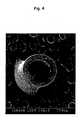
- the spherical structure here refers to a structure in which many spherical or substantially spherical solid contents are combined to each other directly or through streak solid contents. Supposedly, the spherical structure substantially consists of spherulites.
- a spherulite is thermoplastic resin crystals precipitated and solidified when a thermoplastic resin solution is phase-separated to form a porous structure.
- the mean pore size of the three-dimensional network structure is preferably in the range of 5 nm to 50 ⁇ m, and more preferably in the range of 10 nm to 30 ⁇ m.
- the mean pore size of the three-dimensional network structure refers to the mean diameter of the pores in the three-dimensional network structure.
- SEM scanning electron microscope
- the cross section of the porous membrane is photographed through a scanning electron microscope (SEM) or the like at a magnification allowing the pores to be clearly observed, and the diameters of arbitrary 10 or more pores, preferably arbitrary 20 or more pores, are measured and number-averaged.
- the mean pore size may be determined using an image processing system in which the mean diameter of the pores is measured.
- the mean diameter of equivalent rounds is defined as the mean pore size.
- the mean diameter of equivalent rounds is determined by the expression (a x b) 0.5 , wherein a and b are the breadth and the length of elliptical pores, respectively.
- the mean diameter of the spherical structure is preferably in the range of 0.1 ⁇ m to 10 ⁇ m, and more preferably in the range of 0.2 ⁇ m to 5 ⁇ m.
- the surface or cross section of the porous membrane is photographed through a scanning electron microscope or the like at a magnification allowing the spherulites to be clearly observed.
- the diameters of arbitrary 10 or more spherical structures, preferably arbitrary 20 or more spherical structures, are measured and number-averaged.
- the mean diameter may be defined as the mean diameter of equivalent rounds obtained by analyzing the photograph with image processing system.
- a membrane having the spherical structure results in a strong membrane with the permeability maintained. However, it is not easy to enhance the rejection properties.
- the porous membrane of the present invention both a three-dimensional network structure and a spherical structure together, the resulting porous membrane exhibited a high strength, a high permeability, and high rejection properties.
- the mean pore size of the three-dimensional network structure in the range of 5 nm to 50 ⁇ m and the mean diameter of the spherical structure in the range of 0.1 to 10 ⁇ m, the strength, the permeability, and the rejection properties are advantageously brought into balance at a high level.
- a three-dimensional network structure including macro voids particularly with a mean pore size of more than 50 ⁇ m can lead to a membrane having an excellent permeability.
- the strength of the resulting membrane becomes low.
- the three-dimensional network structure and the spherical structure are layered on each other.
- the three-dimensional network structure is disposed on one surface side of the membrane and the spherical structure is disposed on the other side.
- the porous membrane of the present invention has a water permeability in the range of 0.1 to 10 m 3 /m 2 ⁇ h at 50 kPa and 25°C and a rejection of 90% or more for particles with a particle size of 0.843 ⁇ m.
- it also exhibits a fracture strength of 2 MPa or more and a fracture elongation of 15% or more.
- the water permeability is more preferably in the range of 0.15 to 7 m 3 /m 2 ⁇ h.
- the rejection is more preferably at least 95% for particles with a particle size of 0.843 ⁇ m.
- the fracture strength is, more preferably, at least 3 MPa.
- the fracture elongation is, more preferably, at least 20%. If these requirements are satisfied, a porous membrane can be achieved which has sufficient strength, permeability, and rejection property to be used in water treatment, battery separators, charged membranes, fuel cells, blood purification, and the like.
- the porous membrane of the present invention may suitably be used in a hollow fiber form or a flat form.
- the measurements of water permeability and rejection properties were performed on a miniature module of 200 mm in length including four hollow fiber membranes. Reverse osmosis membrane treated water was entirely filtered for 30 minutes by external pressure at a temperature of 25°C and a differential pressure of 16 kPa. Thus, a quantity of permeate (m 3 ) is measured. The quantity of permeate (m 3 ) is converted into a value per hour (h) and a value per effective membrane area (m 2 ). These values were further multiplied by 50/16 and converted into a value at a pressure of 50 kPa. Thus, the water permeability was determined.
- Water in which polystyrene latex particles having a mean particle size of 0.843 ⁇ m were dispersed was entirely filtered for 30 minutes by external pressure at a temperature of 25°C and a differential pressure of 16 kPa.
- the rejection properties can be determined from the ratio of the latex particle concentration in raw water to that in permeate.
- These latex particle concentrations are obtained by measuring absorption coefficients of ultraviolet light having a wavelength of 240 nm.
- the measurements on a flat membrane are performed in the same manner as in the measurement on the hollow fiber membrane, except that the membrane is cut to a circle of 50 mm in diameter and the circle membrane is placed on a cylindrical filtration holder.
- the water permeability may be derived from a value obtained under pressure or aspiration.
- Water temperature may be estimated from the viscosity of liquid to be evaluated.
- a water permeability as low as less than 0.1 m 3 /m 2 ⁇ h is not suitable for the porous membrane because such a water permeability is excessively low.
- the porous membrane has such an excessively large pore size that the impurity rejection properties are negatively affected.
- the rejection is less than 90% for particles with a particle size of 0.843 ⁇ m, the porous membrane undesirably has an excessively large pore size and degraded impurity rejection properties.
- the fracture strength and the fracture elongation can be measured without particular limitation. For example, a tensile test is performed with a tensile tester at a tensile speed of 50 mm/min on more than five samples having a measurement length of 50 mm. Obtained fracture strengths and fracture elongations are averaged. If the fracture strength is less than 2 MPa or the fracture elongation is less than 15%, the porous membrane is difficult to handle and is liable to be fractured by filtration or pressure.
- the preferred mean pore size in the surface of the porous membrane depends on use. However, in the present invention, it is preferable that at least one surface of the porous membrane have a mean pore size of 0.5 ⁇ m or less, and more preferably 0.2 ⁇ m or less.
- the lower limit of the mean pore size in the surface also depends on use, but it is generally preferable to be 0.001 ⁇ m (1 nm) or more.
- the pore size distribution is narrow.
- the mean pore size of the porous membrane surface is preferably in the range of 0.005 to 0.5 ⁇ m, and more preferably in the range of 0.007 to 0.2 ⁇ m.
- a mean pore size in these ranges leads to both high rejection properties and a high water permeability. Also, when the mean pore size is in these ranges, the pores are not easily clogged with water contaminants and, therefore, the water permeability is not negatively affected.
- the porous membrane can, therefore, be used successively for a long time. If clogging occurs, contaminants can easily be removed by backwash or air cleaning.
- the contaminants are different from one water source to another. For example, in the case of a river or a lake, the contaminants include inorganic substances derived from soil and mud and their colloids, microorganisms and their corpses, and humic substances derived from plants and microorganisms.
- the backwash is performed by delivering permeate in a direction reverse to a normal filtration.
- the air cleaning is performed on a hollow fiber membrane by delivering air to vibrate the hollow fiber membrane so that the contaminants deposited on the surface of the membrane are removed.
- Either surface of the membrane may be set to a mean pore size of 0.5 ⁇ m or less.
- the external surface side which comes in contact with water, have a three-dimensional network structure whose mean pore size is 0.5 ⁇ m or less in the external surface, and that the internal surface side have a spherical structure, from the viewpoint of the enhancement of strength, water permeability, rejection properties, and contamination resistance.
- the surface of the porous membrane is photographed through a SEM or the like at a magnification allowing the pores to be clearly observed.
- the diameters of arbitrary 10 or more pores, preferably arbitrary 20 or more pores, are measured and number-averaged.
- the mean pore size may be determined using an image processing system in which the mean diameters of the pores are obtained.
- the mean diameter of equivalent rounds is defined as the mean pore size.
- the mean diameter of equivalent rounds is determined by the expression (a x b) 0.5 , wherein a and b are the breadth and the length of elliptical pores, respectively.
- the resin used in the present invention is not particularly limited, but, preferably, a thermoplastic resin is used because it is easy to form a spherical structure.
- the thermoplastic resin is constituted of a chain macromolecular compound, and is deformed or fluidized by an external force when heated.
- thermoplastic resins include polyethylene, polypropylene, acrylic resins, polyacrylonitrile, acrylonitrile-butadiene-styrene (ABS) resins, polystyrene, acrylonitrile-styrene (AS) resins, vinyl chloride resins, polyethylene terephthalate, polyamide, polyacetal, polycarbonate, modified polyphenylene ether, polyphenylene sulfide, polyvinylidene fluoride, polyamideimide, polyetherimide, polysulfone, polyether sulfone, and their mixtures and copolymers. These resins may be mixed with another resin capable of being blended.
- thermoplastic resin a resin selected from the group consisting of polyethylene resins, polypropylene resins, and polyvinylidene fluoride resins is used as the thermoplastic resin in the present invention because they have high chemical resistance.
- the polyethylene resins used in the present invention contain a polyethylene homopolymer and/or a polyethylene copolymer.
- a plurality of types of polyethylene copolymer may be contained.
- An exemplary polyethylene copolymer may comprise ethylene and at least one straight-chain unsaturated hydrocarbon selected from propylene, butene, pentene, and the like.
- the polypropylene resins used in the present invention contain a polypropylene homopolymer and/or a polypropylene copolymer.
- a plurality of types of polypropylene copolymer may be contained.
- An exemplary polyethylene copolymer may comprise propylene and at least one straight-chain unsaturated hydrocarbon selected from ethylene, butene, pentene, and the like.
- the polyvinylidene fluoride resins used in the present invention contain a vinylidene fluoride homopolymer and/or a vinylidene fluoride copolymer.
- a plurality of types of vinylidene fluoride copolymer may be contained.
- An exemplary vinylidene fluoride copolymer may comprise a vinylidene fluoride and at least one selected from the group consisting of vinyl fluoride, ethylene tetrafluoride, propylene hexafluoride, chlorotrifluoroethylene.
- the weight-average molecular weight of the polyvinylidene fluoride resin is appropriately selected according to the strength and water permeability of the porous membrane required.
- the weight-average molecular weight is preferably in the range of 100 thousand to 700 thousand, and more preferably in the range of 150 thousand to 600 thousand.
- the polyethylene, polypropylene, and polyvinylidene fluoride resins may contain 50 percent by weight or less of another resin capable of being blended.
- the polyvinylidene fluoride resin preferably contains 50 percent by weight or less of an acrylic resin.
- the acrylic resin refers to a macromolecular compound mainly containing a polymer of acrylic acid, a methacrylic acid, or their derivative, such as acrylamide or acrylonitrile.
- acrylic ester resins and methacrylic ester resins are used because they are miscible with polyvinylidene fluoride resins.
- the three-dimensional network structure and the spherical structure may be formed of an identical type of resin or different types of resin.
- both structures advantageously have an affinity for each other.
- each structure is formed of a different type of resin, the strength, water permeability, rejection properties, and other properties can be set in a wider range.
- the spherical structure is preferably formed of a thermoplastic resin, as described above.
- the three-dimensional network structure may be formed of a resins selected from among various types of resin with a wide range of choice.
- Either the three-dimensional network structure or the spherical structure or both may advantageously be formed of a polymer blend containing the same resin as in each other.
- a polymer blend containing the same resin as in each other.
- porous membrane is used as a porous membrane module which is housed in a case having a raw water inlet, a permeate outlet, and the like.
- the porous membrane module is fabricated so as to recover permeate, by housing a bundle of plurality of hollow fiber membranes in a cylindrical container with both ends or one end fixed with a polyurethane or epoxy resin, or by fixing both ends of the hollow fiber membranes in a plate form.
- the porous membrane module is fabricated so as to recover permeate, by folding the porous membrane in a cylindrical manner, around a liquid collection pipe and taking up the membrane in a spiral manner to be housed in a cylindrical container, or by disposing the membrane on both surfaces of a liquid collection board with the periphery fixed water tightly.
- the porous membrane module is provided with at least compression means at the raw water side or suction means at the permeate side to be used as a liquid separation system.
- a compression means a pump may be used, or pressure caused by the difference of water levels may be used.
- a pump or a siphon may be used as the suction means.
- This liquid separation system can be used for water purification, clean water treatment, effluent treatment, industrial water production, and the like in the field of water treatment.
- river water, lake water, groundwater, seawater, sewage, discharged water, and the like are treated.
- the above-described porous membrane can also be used for a battery separator for separating the positive electrode and the negative electrode in a battery. In this instance, it is expected to enhance battery performance because of a high ion permeability and to enhance the durability of the battery because of a high fracture strength.
- the porous membrane prepared by the above-described manufacturing method is used as a charged membrane by introducing charged groups (ion exchange groups).
- the charged membrane is expected to achieve the effects of improving ion recognition properties and enhancing the durability because of a high fracture strength.
- the porous membrane is used as an ion exchange membrane for a fuel cell by impregnating the porous membrane with an ion exchange resin.
- an ion exchange resin used as a fuel
- the swelling of the ion exchange membrane with methanol is suppressed and the methanol is prevented from leaking from the anode to the cathode through the ion exchange membrane, that is, so-called crossover is prevented.
- the performance of the fuel cell is enhanced.
- it is expected to enhance the durability of the fuel cell because of a high fracture strength.
- the above-described porous membrane is also used as a blood purification membrane.
- This blood purification membrane is expected to increase the properties of removing waste products in blood, and to enhance the durability of the blood purification membrane because of a high fracture strength.
- the porous membrane having both a three-dimensional network structure and a spherical structure can be manufactured by various techniques.
- both the three-dimensional network structure and the spherical structure may be simultaneously formed of an identical resin solution.
- the three-dimensional network structure may be layered on at least one surface of a porous membrane having the spherical structure.
- at least two types of resin solutions may be discharged from an extrusion head at one time to form the three-dimensional network structure and the spherical structure simultaneously.
- thermoplastic resin is dissolved in a poor or good solvent for the resin to be a relatively high concentration in the range of about 20 to 60 percent by weight.
- This thermoplastic resin solution is cooled to solidify.
- a three-dimensional network structure and a spherical structure are simultaneously formed.
- the poor solvent refers to a solvent incapable of dissolving 5 percent by weight or more of resin at a low temperature of 60°C or less, but capable of dissolving 5 percent by weight or more of rein at a high temperature between 60°C and the melting point of the resin (for example, about 178°C when the resin comprises a vinylidene fluoride homopolymer).
- a solvent capable of dissolving 5 percent by weight or more of resin at a temperature as low as 60°C or less is defined as a good solvent.
- a solvent not allowing a resin to dissolve or swell is defined as a nonsolvent.
- exemplary poor solvents include alkyl ketones, esters, glycol esters and organic carbonates having a medium chain length; such as cyclohexanone, isophorone, ⁇ -butyrolactone, methyl isoamyl ketone, dimethyl phthalate, propylene glycol methyl ether, propylene carbonate, diacetone alcohol, and glycerol triacetate; and their mixtures.
- a mixture of a nonsolvent and a poor solvent, satisfying the above-described definition is defined as a poor solvent.
- Exemplary good solvents include lower alkyl ketones, such as N-methyl-2-pyrrolidone, dimethyl sulfoxide, dimethylacetamide, dimethylformamide, methyl ethyl ketone, acetone, tetrahydrofuran, tetramethylurea, and trimethyl phosphate; esters; amides; and their mixtures.
- nonsolvents include water, hexane, pentane, benzene, toluene, methanol, ethanol, carbon tetrachloride, o-dichlorobenzene, trichloroethylene, ethylene glycol, diethylene glycol, triethylene glycol, propylene glycol, butylene glycol, pentanediol, hexanediol, aliphatic hydrocarbons such as low-molecular-weight polyethylene glycols, aromatic hydrocarbons, aliphatic polyhydric alcohols, aromatic polyhydric alcohols, chlorinated hydrocarbons, other chlorinated organic liquids, and their mixtures.
- thermoplastic resin is dissolved in a poor or good solvent for the resin at a relatively high temperature in the range of 80 to 170°C to prepare a thermoplastic resin solution having a relatively high concentration in the range of 20 to 60 percent by weight.
- the resin concentration increases, the resulting porous membrane exhibits higher stretch properties.
- an excessively high concentration reduces the void ratio and the water permeability is negatively affected.
- the viscosity of the prepared resin solution is set in a proper range, the resulting membrane does not become porous. More preferably, the resin concentration is in the range of 30 to 50 percent by weight.
- the solidification of the resin solution is, preferably, performed by cooling solidification in which the resin solution is discharged into a cool bath from an extrusion head.
- a liquid with a temperature in the range of 5 to 50°C, containing 60 to 100 percent of a poor or good solvent is used as a cooling liquid in the cool bath.
- the cooling liquid may contain a nonsolvent in addition to the poor or good solvent.
- the membrane having the spherical structure exhibits a high strength and a high water permeability.
- Whether the membrane has a spherical structure or a network structure is set by selecting a combination of the concentration of the resin solution, the composition of the solvent for dissolving the resin, and the temperature of the cooling liquid in the cool bath.
- the concentration of the resin solution is set in the range of 10 to 20 percent by weight so as to achieve a water permeability, the resulting membrane has a network structure with macro voids and does not exhibit a high stretch.
- the combination of the composition of the solvent for dissolving the resin and the composition of the cooling liquid in the cool bath is important, as well as the concentration of the resin solution.
- the resin solution applied on one surface of the membrane be solidified using a cooling liquid having a different composition from the composition for the other surface.
- the combinations of the composition of the resin solution and the composition of the cooling liquid are adjusted so as to form a three-dimensional network structure on one surface and form a spherical structure on the other surface.
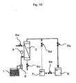
- the porous membrane is formed in a hollow fiber, after a resin solution is prepared, the resin solution and a lumen forming fluid are respectively discharged from the external pipe and the internal pipe of a double co-extrusion head for spinning hollow fiber membranes, while being solidified in a cool bath.
- a gas or a liquid may be used as the lumen forming fluid.
- the same liquid as the cooling liquid is preferably used, which contains 60 to 100 percent of a poor solvent or good solvent.
- the lumen forming fluid may be supplied with cooling. However, if the cool bath has sufficient power to solidify the hollow fiber membrane, the lumen forming fluid may be supplied without cooling.
- the porous membrane is formed in a flat membrane, after a resin solution is prepared, the resin solution is discharged from a slit extrusion head and solidified in a cool bath.
- the resulting flat membrane can have both a three-dimensional network structure and a spherical structure.
- the method for varying the cooling liquid compositions coming into contact with one surface of the flat membrane and with the other surface is not particularly limited. However, for example, a cooling liquid is sprayed from one side of the flat membrane and another cooling liquid is sprayed from the other side.
- the method for bringing only one side of the flat membrane into contact with a cool bath is not particularly limited. However, for example, the flat membrane may be floated on the surface of the cool bath, or a cooling liquid may be sprayed from only one side of the flat membrane.
- a porous substrate may further be bonded so as to support the porous membrane to give a strength to the membrane, because the fracture strength is enhanced.
- the material of the porous substrate is not particularly limited, and organic materials and inorganic materials may be used. However, organic materials are preferable from the viewpoint of weight saving. More preferably, a woven or nonwoven textile comprising a organic fiber, such as a cellulose fiber, a cellulose triacetate fiber, a polyester fiber, a polypropylene fiber, and a polyethylene fiber, may be used.
- the manufacturing method up to this point can provide a water-permeable porous membrane having high stretch properties.
- the porous membrane may further be drawn at a draw ratio in the range of 1.1 to 5.0. This is a preferred form of embodiments of the invention because the water permeability of the porous membrane is enhanced.
- a layer having a three-dimensional network structure is formed afterward on at least one surface of a porous membrane having a spherical structure.
- a porous membrane having a spherical structure is formed.
- the method for forming the porous membrane having the spherical structure is not particularly limited, but, preferably, the foregoing method may be applied.
- a layer having a three-dimensional network structure is formed on at lest one surface of the resulting porous membrane having the spherical structure.
- the method for this is not particularly limited, but, preferably, the following method is applied. Specifically, after a resin solution is applied onto at least one surface of the porous membrane having the spherical structure, the membrane is immersed in a solidification liquid. Thus, a layer having a three-dimensional network structure is formed.
- Exemplary resins used here include acrylic resins, polyacrylonitrile resins, acrylonitrile-butadiene-styrene (ABS) resins, polystyrene resins, acrylonitrile-styrene (AC) resins, vinyl chloride resins, polyethylene terephthalate resins, polyamide resins, polyacetal resins, polycarbonate resins, modified polyphenylene ether resins, polyphenylene sulfide resins, polyvinylidene fluoride resins, polyamideimide resins, polyetherimide resins, polysulfone resins, polyether sulfone resins, and their mixtures and copolymers. These resins may contain another resin capable of being blended, a polyhydric alcohol, or a surfactant in an amount of 50 percent by weight or less.
- a resin selected from the group consisting of polysulfone resins, polyether,sulfone resins, acrylic resins, polyacrylonitrile resins and polyvinylidene fluoride resins is used because they are chemical resistant.
- a good solvent for the resin is preferably used as a solvent for dissolving the resin.
- the foregoing substances may be used.
- the concentration of the resin is generally preferably in the range of 5 to 30 percent by weight, and more preferably in the range of 10 to 25 percent by weight. If the resin concentration is less than 5 percent by weight, the physical durability of the layer having the three-dimensional network structure is negatively affected. If the resin concentration is more than 30 percent by weight, a high pressure is required when a liquid is allowed to permeate.
- the method for applying the resin solution onto at least one surface of the porous membrane having the spherical structure is not particularly limited. However, preferably, the porous membrane is immersed in the solution, or the solution is applied onto at least one surface of the porous membrane. If the porous membrane is formed in a hollow fiber, in order to apply the solution onto the external surface of the hollow fiber membrane, the hollow fiber membrane may be immersed in the solution or the solution may be dripped onto the hollow fiber membrane. Also, in order to apply the solution onto the internal surface of the hollow fiber membrane, preferably, the solution is injected into the hollow fiber membrane.
- part of the applied solution may be scraped off or blown off with an air knife, in addition to the method of controlling the solution amount itself.
- a solidification liquid contains a nonsolvent for the resin.
- the nonsolvent the foregoing substances may be used. By bring the resin solution into contact with the nonsolvent, nonsolvent induced phase separation occurs to form a layer having a three-dimensional network structure.
- the method for setting the mean pore size in the surface in the foregoing range depends on the type of resin, but, for example, the following method may be applied.
- An additive is added to the resin solution.
- the additive is eluted when or after the three-dimensional network structure is formed.
- the mean pore size in the surface is controlled.
- Organic compounds or inorganic compounds may be used as the additive.
- the organic compounds are capable of dissolving in both the solvent for the resin and the nonsolvent causing nonsolvent induced phase separation.
- Exemplary organic compounds include water-soluble polymer, such as polyvinylpyrrolidone, polyethylene glycol, polyvinyl alcohol, polyethyleneimine, polyacrylic acid, and dextran; surfactants; glycerine; and saccharides.
- the inorganic compounds are soluble in water.
- Exemplary inorganic compounds include calcium chloride, lithium chloride, and barium sulfate.
- the mean pore size in the surface is controlled by selecting the type, concentration, and temperature of the nonsolvent in the solidification liquid so as to adjust the phase separation speed, instead of using the additive. In general, a high phase separation speed leads to a small mean pore size in the surface, and a low phase separation speed leads to a large mean pore size. Also, it is advantageous to add a nonsolvent to the resin solution for controlling the phase separation speed.
- Still another method for forming a porous membrane having both a three-dimensional network structure and a spherical structure will now be described.
- two or more types of resin solution are simultaneously discharged from an extrusion head to form a three-dimensional network structure and a spherical structure at one time.
- the three-dimensional network structure and the spherical structure are formed, for example, by discharging a resin solution for forming the three-dimensional network structure and a resin solution for forming the spherical structure and subsequently solidifying the solutions. Since this method allows simultaneous formation of the three-dimensional network structure and the spherical structure, manufacturing processes are advantageously simplified.
- the resin solution for forming the three-dimensional network structure is not particularly limited as long as it is solidified to result in a three-dimensional network structure.
- a solution may be used which is prepared by dissolving a resin in a solvent and in which nonsolvent induced phase separation is caused by coming into contact with a solidification bath.
- the resin solution for forming the spherical structure is not particularly limited as long as it is solidified to result in a spherical structure.
- a solution may be used which is prepared by dissolving a thermoplastic resin, such as a polyvinylidene fluoride resin, in a relatively high concentration of about 20 to 60 percent by weight, in a poor or good solvent for the resin at a relatively high temperature (about 80 to 170°C).
- a thermoplastic resin such as a polyvinylidene fluoride resin
- a poor or good solvent for the resin at a relatively high temperature (about 80 to 170°C).
- the thermoplastic resin, solidification bath, and poor or good solvent preferably, the foregoing substances are used.
- the extrusion head for simultaneously discharging the resins solution for forming the three-dimensional network structure and the spherical structure is not particularly limited. However, if the porous membrane is formed in a flat membrane, a double-slit head having two slits is preferably used. If the porous membrane is formed in a hollow fiber membrane, a triple co-extrusion head is preferably used. The resins for forming the three-dimensional network structure and the spherical structure are discharged from the external pipe and the middle pipe of the triple co-extrusion head and a lumen forming fluid is discharged from the internal pipe, while they are solidified in a cool bath. Thus, a hollow fiber membrane is formed.
- the amount of lumen forming fluid can advantageously be set to be smaller than that of the cooling liquid used for forming a flat membrane.
- a hollow fiber membrane which has the three-dimensional network structure on the internal side and the spherical structure on the external side.
- porous membrane is used as a porous membrane module which is housed in a case having a raw water inlet, a permeate outlet, and the like.
- a porous membrane formed in a hollow fiber membrane is uses as a hollow fiber membrane module.
- Fig. 9 shows an example of the hollow fiber membrane module.
- Several hundreds to tens of thousands of hollow fiber membranes 2 are tied in a bundle to prepare a hollow fiber bundle 3.
- the hollow fiber bundle 3 is housed in a cylindrical case 1. Both ends of the cylindrical case 1 are sealed with sealants 3A and 3B secured to the internal walls of the cylindrical case 1.
- a filtration chamber 4 is provided in the space between the sealants 3A and 3B in the cylindrical case.
- the hollow fiber bundle 3 is placed in the filtration chamber 4.
- the hollow fiber bundle 3 may be disposed in a U shape in the cylindrical case 1. However, in the present invention, it is disposed in line with being fixed by the sealants and each lumen of the hollow fiber membranes 2 is open to the external surface of one or both of the sealants.
- the sealants 3A and 3B are formed by injecting a fluid resin into the interstices between the hollow fiber membranes constituting the hollow fiber bundle and, subsequently, solidifying the resin.
- the solidified resin, constituting the sealants 3A and 3B, is integrated with the hollow fiber membranes 3 and further integrated with the internal walls of the cylindrical case 1 (such a sealing manner with a resin is referred to as potting).
- the portions corresponding to the ends of the openings of the completed hollow fiber membranes 2, acting as a final product, are filled with a resin or crashed to close the openings in advance so that the potting resin is prevented from permeating.
- part of the sealants formed by potting is cut away such that the previously filled portions of the lumens are removed.
- raw water is supplied to the filtration chamber under pressure.
- the raw water reaches the lumens of the hollow fiber membranes through the hollow fiber membranes in the filtration chamber.
- the raw water is filtrated to be permeate.
- the permeate is discharged from the openings of the hollow fiber membranes.
- the hollow fiber membrane module formed as in above is provided with at least compression means at the raw water side or suction means at the permeate side.
- Fig. 10 shows an example of a water separation apparatus using a hollow fiber membrane module.
- the raw water stored in a raw water tank 1 is pressurized with a booster pump 2 and is subsequently supplied to the membrane module 3.
- the pressure of the supplied raw water is measured with a pressure gauge 4, if necessary.
- the raw water is separated into permeate and concentrated water through the membrane module 3.
- the concentrated water is drained outside and the permeate is stored in a treated water tank 5.
- a backwash water tank 7 is provided.
- the membrane module 3 is cleaned. This water flow is controlled by valves 6a to 6d.
- As the compression means pressure caused by the difference of water levels may be used instead of the pump.
- a pump or a siphon may be used as the suction means.
- a flat porous membrane is used as a spiral element or a plate-and-frame element.
- These elements are also provided with at least compression means at the raw water side or suction means at the permeate side.
- a pump may be used, or pressure caused by the difference of water levels may be used.
- a pump or a siphon may be used as the suction means.
- Fig. 11 shows an example of a spiral element.
- a spiral element 15 a porous membrane 18 formed in a bag-like manner with a feed water spacer 17 wrapped therein is wound on a center pipe 16 in a spiral manner with a permeate spacer 19 in gaps between turns of the membrane.
- a brine seal 20 is provided at one end of the spiral element.
- the spiral element 15 guides water supplied, under a prescribed pressure, from the brine seal 20 side to the porous membrane 18 through the permeate spacer 19. Permeate which has passed through the porous membrane 18 is taken out through the center pipe 16.
- Such an element having this structure can have a membrane area larger than that of a plate-and-frame element, described later, and, accordingly the amount of permeate can advantageously be set large.
- the spiral element is rather vulnerable to contamination. It is, therefore, suitable for clean raw water (such as clean sea water, brine water, and river water).
- Fig. 12 shows an example of a plate-and-frame element.
- a permeate spacer 28 and a porous membrane 29 are disposed in that order on both surfaces of a supporting plate 27 having a high stiffness and the periphery is water-tightly fixed.
- Each surface of the supporting plate 27 has protuberances and a recess.
- the porous membrane 29 filters out maximities in water.
- the permeate spacer 28 is intended to efficiently deliver the permeate filtered through the porous membrane 29 to the supporting plate 27.
- the permeate flowing to the supporting plate 27 is taken out outside through the recesses of the supporting plate 27.
- the permeate spacer 28 and the porous membrane 29 are disposed at only one surface side of the supporting plate 27. However, by disposing them at both surfaces, the membrane area can be increased.
- the permeate filtered through the porous membrane 29 passes through the permeate spacer 28 and the recess of the supporting plate 27, and is finally taken out of a permeate outlet 30 to the outside of the element.
- a porous membrane module is such that a plurality of above-described elements are disposed, in a housing, parallel to one another such as to form spaces between the surfaces thereof.
- FIG. 13 is a schematic illustration of an MEA (membrane electrode assembly) of a direct methanol fuel cell.
- An electrolyte 31 is disposed between an anode 32 and a cathode 30.
- an electromotive force is generated.
- the pores of the porous membrane of the present invention is impregnated with an electrolyte, such as a polymer electrolyte.
- the porous membrane is used as the electrolyte membrane 31.
- a cross section of each porous membrane was photographed at a magnification of 1,000 or 10,000 through an SEM (S-800) (manufactured by Hitachi, Ltd.).
- S-800 manufactured by Hitachi, Ltd.
- the pore sizes and the diameters in the spherical structure of arbitrary 10 to 50 pores were measured and number-averaged.
- a cross section of the porous membrane was photographed at a magnification of 1,000 or 10,000 through the above-mentioned SEM.
- the pore sizes of arbitrary 10 to 50 pores were measured and number-averaged.
- the measurements of the water permeability and rejection property of the hollow fiber porous membrane were performed on a miniature module of 200 mm in length including four hollow fiber membranes.
- the measurements were performed on a membrane which is cut to a circle of 50 mm in diameter and set in a cylindrical filtration holder.
- Reverse osmosis membrane treated water was entirely filtered for 30 minutes by external pressure at a temperature of 25°C and a differential pressure of 16 kPa.
- the quantity of permeate (m 3 ) was converted into a value per hour (h) and a value per effective membrane area (m 2 ). These values were further multiplied by 50/16 and converted into a value at a pressure of 50 kPa.
- the water permeability was determined.
- the fracture strength and the fracture elongation were determined by a tensile test using a tensile tester (TENSILON/RTM-100) (manufactured by Toyo Baldwin). The tensile test was performed on five samples having a measurement length of 50 mm at a tensile speed of 50 mm/min, and obtained fracture strengths and fracture elongations were averaged.
- TENSILON/RTM-100 tensile tester
- a vinylidene fluoride homopolymer having a weight-average molecular weight of 417 thousand in an amount of 38 percent by weight was mixed with 31 percent by weight of ⁇ -butyrolactone and 31 percent by weight of diethylene glycol and dissolved at a temperature of 200°C.
- This resin solution was discharged with ⁇ -butyrolactone, acting as a lumen forming fluid, from a double co-extrusion head with a temperature of 190°C, and was solidified in a bath with a temperature of 12°C containing an aqueous solution of 80 percent by weight ⁇ -butyrolactone.
- the resulting hollow fiber membrane had an outer diameter of 1.60 mm and an inner diameter of 0.90 mm.
- FIG. 1 shows an SEM photograph of an entire section of the hollow fiber membrane
- Fig. 2 shows an SEM photograph of a section around the external surface
- Fig. 3 shows an SEM photograph of a section around the internal surface.
- the area around the external surface had a three-dimensional network structure and the area around the internal surface had a spherical structure.
- the mean pore size of the three-dimensional network structure was 1.63 ⁇ m, and the mean diameter of the spherical structure was 4.06 ⁇ m.
- the water permeability at 50 kPa and 25°C was 0.30 m 3 /m 2 ⁇ h.
- the rejection for particles having a particle size of 0.843 ⁇ m was 98%.
- the fracture strength and the fracture elongation were 7.8 MPa and 104%, respectively.
- the hollow fiber membrane had a dense surface and exhibited excellent water permeability, rejection properties, strength, and elongation.
- a vinylidene fluoride homopolymer having a weight-average molecular weight of 417 thousand in an amount of 38 percent by weight was mixed with 31 percent by weight of ⁇ -butyrolactone and 31 percent by weight of diethylene glycol and dissolved at a temperature of 200°C.
- This resin solution was discharged with ⁇ -butyrolactone, acting as a lumen forming fluid, from a double co-extrusion head with a temperature of 180°C, and was solidified in a bath with a temperature of 17°C containing an aqueous solution of 80 percent by weight ⁇ -butyrolactone.
- the resulting hollow fiber membrane had an outer diameter of 1.50 mm and an inner diameter of 0.92 mm.
- the area around the external surface had a three-dimensional network structure and the area around the internal surface had a spherical structure.
- the mean pore size of the three-dimensional network structure was 1.73 ⁇ m, and the mean diameter of the spherical structure was 4.89 ⁇ m.
- the water permeability at 50 kPa and 25°C was 0.35 m 3 /m 2 ⁇ h.
- the rejection for particles having a particle size of 0.843 ⁇ m was 97%.
- the fracture strength and the fracture elongation were 8.8 MPa and 100%, respectively.
- the hollow fiber membrane had a dense surface and exhibited excellent water permeability, rejection properties, strength, and elongation.
- a vinylidene fluoride homopolymer having a weight-average molecular weight of 417 thousand in an amount of 38 percent by weight was mixed with 41 percent by weight of ⁇ -butyrolactone and 21 percent by weight of diethylene glycol and dissolved at a temperature of 200°C.
- This resin solution was discharged with ⁇ -butyrolactone, acting as a lumen forming fluid, from a double co-extrusion head with a temperature of 160°C, and was solidified in a bath with a temperature of 12°C containing an aqueous solution of 80 percent by weight ⁇ -butyrolactone.
- the resulting hollow fiber membrane had an outer diameter of 1.54 mm and an inner diameter of 0.93 mm.
- the area around the external surface had a three-dimensional network structure and the area around the internal surface had a spherical structure.
- the mean pore size of the three-dimensional network structure was 1.26 ⁇ m, and the mean diameter of the spherical structure was 2.61 ⁇ m.
- the water permeability at 50 kPa and 25°C was 0.20 m 3 /m 2 ⁇ h.
- the rejection for particles having a particle size of 0.843 ⁇ m was 99%.
- the fracture strength and the fracture elongation were 5.5 MPa and 99%, respectively.
- the hollow fiber membrane had a dense surface and exhibited excellent water permeability, rejection properties, strength, and elongation.
- a vinylidene fluoride homopolymer having a weight-average molecular weight of 417 thousand in an amount of 38 percent by weight was mixed with 41 percent by weight of ⁇ -butyrolactone and 21 percent by weight of diethylene glycol and dissolved at a temperature of 200°C.
- This resin solution was discharged with ⁇ -butyrolactone, acting as a lumen forming fluid, from a double co-extrusion head with a temperature of 150°C, and was solidified in a bath with a temperature of 14°C containing an aqueous solution of 80 percent by weight ⁇ -butyrolactone.
- the resulting hollow fiber membrane had an outer diameter of 1.56 mm and an inner diameter of 0.98 mm.
- the area around the external surface had a three-dimensional network structure and the area around the internal surface had a spherical structure.
- the mean pore size of the three-dimensional network structure was 1.22 ⁇ m, and the mean diameter of the spherical structure was 3.51 ⁇ m.
- the water permeability at 50 kPa and 25°C was 0.25 m 3 /m 2 ⁇ h.
- the rejection for particles having a particle size of 0.843 ⁇ m was 98%.
- the fracture strength and the fracture elongation were 6.0 MPa and 23%, respectively.
- the hollow fiber membrane had a dense surface and exhibited excellent water permeability, rejection properties, strength, and elongation.
- a vinylidene fluoride homopolymer having a weight-average molecular weight of 417 thousand in an amount of 38 percent by weight was mixed with 31 percent by weight of ⁇ -butyrolactone and 31 percent by weight of diethylene glycol and dissolved at a temperature of 200°C.
- This resin solution was discharged from a slit head with a temperature of 190°C.
- ⁇ -butyrolactone with a temperature of 12°C was sprayed onto on surface of the discharged resin and an aqueous solution of 80 percent by weight of ⁇ -butyrolactone was sprayed onto the other surface.
- the resulting flat membrane had a thickness of 0.175 mm.
- the mean pore size of the three-dimensional network structure was 1.60 ⁇ m, and the mean diameter of the spherical structure was 4.10 ⁇ m.
- the water permeability at 50 kPa and 25°C was 0.25 m 3 /m 2 ⁇ h.
- the rejection for particles having a particle size of 0.843 ⁇ m was 98%.
- the fracture strength and the fracture elongation were 7.5 MPa and 40%, respectively.
- the flat membrane had a dense surface and exhibited excellent water permeability, rejection properties, strength, and elongation.
- a vinylidene fluoride homopolymer having a weight-average molecular weight of 417 thousand was mixed with dimethyl sulfoxide at a ratio of 20 to 80 percent by weight, respectively, and was dissolved at a temperature of 70°C.
- This resin solution was discharged with an aqueous solution of 50 percent by weight dimethyl sulfoxide, acting as a lumen forming fluid, from a double co-extrusion head with a temperature of 50°C, and was solidified in a bath with a temperature of 50°C containing an aqueous solution of 50 percent by weight dimethyl sulfoxide.
- the resulting hollow fiber membrane had an outer diameter of 1.40 mm and an inner diameter of 0.98 mm.
- the external surface of the resin had a dense layer and the internal surface had an asymmetrical three-dimensional network structure with macro voids. There was no spherical structure.
- the water permeability at 50 kPa and 25°C was as low as 0.08 m 3 /m 2 ⁇ h.
- the rejection for particles having a particle size of 0.843 ⁇ m was 99%.
- the fracture strength and the fracture elongation were 1.0 MPa and 48%, respectively. Thus, the strength was low.
- a vinylidene fluoride homopolymer having a weight-average molecular weight of 417 thousand was mixed with ⁇ -butyrolactone at a ratio of 38 to 62 percent by weight, respectively, and was dissolved at a temperature of 170°C.
- This resin solution was discharged with ⁇ -butyrolactone, acting as a lumen forming fluid, from a double co-extrusion head with a temperature of 100°C, and was solidified in a cool bath with a temperature of 20°C containing an aqueous solution of 80 percent by weight ⁇ -butyrolactone.
- the resulting hollow fiber membrane had an outer diameter of 1.01 mm and an inner diameter of 0.72 mm.
- FIG. 4 shows an SEM photograph of an entire section of this hollow fiber membrane
- Fig. 5 shows an SEM photograph of a section around the external surface
- Fig. 6 shows an SEM photograph of a section around the internal surface.
- This membrane had only a spherical structure having a mean diameter of 2.75 ⁇ m.
- the water permeability at 50 kPa and 25°C was 0.30 m 3 /m 2 ⁇ h.
- the rejection for particles having a particle size of 0.843 ⁇ m was 80%.
- the fracture strength and the fracture elongation were 5.3 MPa and 48%, respectively.
- the hollow fiber membrane exhibited an excellent water permeability, strength, and elongation, its rejection properties were inferior.
- a catalyst-supporting carbon (catalyst: 29.2 percent by weight of platinum and 15.8 percent by weight of ruthenium, carbon: Vulcan (registered trade mark) XC-72 produced by Cabot) was added into a Nafion (registered trade mark) solution (bought from Aldrich) such that the weight ratio was 1 to 1.
- the mixture was sufficiently stirred to prepare a catalyst-polymer composition.
- This catalyst-polymer composition was applied onto one surface of a carbon paper TGP-H-060, produced by Toray, to prepare an electrode base with an electrode catalyst layer, supporting 3 mg/cm 2 of platinum.
- Example 5 the flat membrane produced in Example 5 was immersed in a Nafion (registered trade mark) solution (bought from Aldrich) and subsequently dried to prepare an ion exchange membrane.
- the ion exchange membrane serves as an electrolyte membrane.
- Respective two electrode bases serve as a cathode and an anode.
- the electrodes bases were disposed such that each electrode catalyst layer side of the bases opposes the ion exchange membrane. This composite was hot-pressed under the conditions of 130°C and 5 MPa. Thus, a membrane-electrode integrated unit was prepared.
- the resulting membrane-electrode integrated unit was incorporated into a fuel cell.
- An aqueous solution of 64 percent by weigh methanol and air were supplied to the anode side and the cathode side, respectively.
- the fuel cell outputs a maximum power of 0.5 mW/cm 2 and, thus, exhibited excellently high power properties. This is probably because the swelling of the ion exchange membrane with methanol is suppressed and the leak of methanol through the ion exchange membrane from the anode to cathode, that is, crossover, is prevented.
- Electrode bases with an electrode catalyst layer prepared under the same conditions as in Example 6 were layered on both surfaces of an ion exchange membrane Nafion (registered trade mark) 117 (0.175 mm in thickness), produced by Du Pont.
- the electrode bases were disposed such that each electrode catalyst layer side of the bases opposes the ion exchange membrane. This composite was hot-pressed under the same conditions as in Example 6. Thus, a membrane-electrode integrated unit was prepared.
- the resulting membrane-electrode integrated unit was evaluated under the same conditions as in Example 6.
- the maximum power was as low as 0.1 mW/cm 2 . This is probably because the ion exchange membrane Nafion (registered trade mark) 117 was welled with methanol and, consequently, crossover of methanol occurred.
- Hollow fiber membranes were prepared by the following method. First, hollow fiber membranes of Comparative Examples 4 to 15 were prepared under the conditions shown in Table 1. Vinylidene fluoride homopolymer was mixed with a solvent to be dissolved. The solution was discharged with a lumen forming fluid from a double co-extrusion head and solidified in a cool bath. Each hollow fiber membrane had only a spherical structure.
- a mixed solution containing 13 percent by weight of vinylidene fluoride homopolymer having a weight-average molecular weight of 284 thousand, 5 percent by weight of polyethylene glycol having a weight-average molecular weight of 20 thousand, 79 percent by weight of dimethylformamide, and 3 percent by weight of water was uniformly applied onto the surfaces of the hollow fiber membranes of Comparative Examples 4 to 15.
- These hollow fiber membranes were immediately immersed in a mixed solvent containing 95 percent by weight of water and 5 percent by weight of dimethylformamide to solidify the solution. These are defined as Examples 7 to 18.
- These hollow fiber membranes each had a three-dimensional network structure on the external side and a spherical structure on the internal side. The thickness of the three-dimensional network structure was 20 ⁇ m.
- Table 2 show properties of hollow fiber membranes of Examples 7 to 18 and Comparative Examples 4 to 15. Each example exhibited higher rejection properties than those of the comparative examples.
- Table 1 PVDF weight-average molecular weight Solvent Ratio of polymer to solvent Dissolving temp. (°C) Lumen forming fluid composition Head temp. (°C) Cool bath composition Cool bath temp.
- Hollow fiber membranes were prepared by the following method. First, hollow fiber membranes of Comparative Examples 16 to 27 were prepared under the conditions shown in Table 3. Vinylidene fluoride homopolymer was mixed with a solvent to be dissolved. The solution was discharged with a lumen forming fluid from a double co-extrusion head and solidified in a cool bath. Then, the product was drawn in a drawing bath.
- Fig. 7 shows an SEM photograph of a cross section around the external surface of a hollow fiber membrane prepared in Comparative Example 23, as a typical example. Each hollow fiber membrane of Comparative Examples 16 to 27 had only a spherical structure.
- FIG. 8 shows an SEM photograph of a cross section around the external surface of a hollow fiber membrane prepared in Example 26, as a typical example.
- Each hollow fiber membrane of Examples 19 to 30 had a spherical structure on the internal side and a three-dimensional network structure on the external side. The thickness of the three-dimensional network structure was 20 ⁇ m.
- Table 4 show properties of hollow fiber membranes of Examples 19 to 30 and Comparative Examples 16 to 27. Each example exhibited higher rejection properties than those of the comparative examples.
- Table 3 PVDF weight-average molecular weight Solvent Ratio of polymer to solvent Dissolving temp. (°C) Lumen forming fluid composition Head temp. (°C) Cool bath composition Cool bath temp. (°C) Drawing bath Drawing bath temp.
- a solution containing 8 percent by weight of polyacrylonitrile polymer having a weight-average molecular weight of 400 thousand and 92 percent by weight of dimethyl sulfoxide was applied onto the surfaces of Comparative Examples 16 to 27. These hollow fiber membranes were immediately immersed in a mixed solvent containing 90 percent by weight of water and 10 percent by weight of dimethyl sulfoxide to solidify the solution. These are defined as Examples 31 to 42. These hollow fiber membranes of Examples 31 to 42 each had a three-dimensional network structure on the external side and a spherical structure on the internal side. The thickness of the three-dimensional network structure was 20 to 30 ⁇ m. Table 5 show properties of hollow fiber membranes of Examples 31 to 42. Each example exhibited higher rejection properties than those of the comparative examples.
- a solution containing 2 percent by weight of polysulfone having a weight-average molecular weight of 47 thousand, 6 percent by weight of polysulfone having a weight-average molecular weight of 59 thousand, 3 percent by weight of polyvinylpyrrolidone having a weight-average molecular weight of 1200 thousand, 88 percent by weight of dimethylacetamide, and 1 percent by weight of water was applied onto the surfaces of Comparative Examples 16 to 27. These hollow fiber membranes were immediately immersed in a solidification bath with a temperature of 40°C containing 10 percent by weight of mixed solvent containing 10 percent by weight of dimethyl sulfoxide, 30 percent by weight of dimethylacetamide, and 60 percent by weight of water to solidify the solution.
- Examples 43 to 54 These are defined as Examples 43 to 54.
- These hollow fiber membranes of Examples 43 to 54 each had a three-dimensional network structure on the external side and a spherical structure on the internal side. The thickness of the three-dimensional network structure was about 30 ⁇ m.
- Table 6 show properties of hollow fiber membranes of Examples 43 to 54. Each example exhibited higher rejection properties than those of the comparative examples.
- a vinylidene fluoride homopolymer having a weight-average molecular weight of 358 thousand, a copolymer of ethylene tetrafluoride and vinylidene fluoride (ATOFINA Japan, Kynar (registered trade mark) 7201, weight ratio: 3:7), and cyclohexanone were mixed in amounts of 30, 10, and 60 percent by weight, respectively, and the resins were dissolved at 165°C.
- This polymer solution was discharged with 100% cyclohexanone, acting as a lumen forming fluid, from a double co-extrusion head with a temperature of 145°C, and was solidified in a cool bath with a temperature of 30°C containing an aqueous solution of 90 percent by weight cyclohexanone.
- the product was drawn to 3.0 times in water with a temperature of 80°C to obtain a hollow fiber membrane.
- a mixed solution containing 13 percent by weight of vinylidene fluoride homopolymer having a weight-average molecular weight of 284 thousand, 5 percent by weight of polyethylene glycol having a weight-average molecular weight of 20 thousand, 79 percent by weight of dimethylformamide, and 3 percent by weight of water was uniformly applied onto the surfaces of this hollow fiber membrane.
- the hollow fiber membrane was then immediately immersed in a mixed solvent containing 95 percent by weight of water and 5 percent by weight of dimethylformamide.
- the resulting hollow fiber membrane had a three-dimensional network structure on the external side and a spherical structure on the internal side. The thickness of the three-dimensional network structure was 20 ⁇ m.
- the hollow fiber membrane had an outer diameter of 1.44 mm and an inner diameter of 0.90 mm.
- the external surface of the hollow fiber membrane had pores with a mean pore size of 0.11 ⁇ m.
- the water permeability (conditions: differential pressure 50 kPa, 25°C) was 0.44 m 3 /m 2 ⁇ h.
- the rejection was 97%.
- the fracture strength and the fracture elongation were 15.61 MPa and 55%, respectively.
- the hollow fiber membrane exhibited excellent water permeability, rejection properties, strength, and elongation.
- a vinylidene fluoride homopolymer having a weight-average molecular weight of 358 thousand, a copolymer of ethylene tetrafluoride and vinylidene fluoride (ATOFINA Japan, Kynar (registered trade mark) 7201, weight ratio: 3:7), and cyclohexanone were mixed in amounts of 30, 10, and 60 percent by weight, respectively, and the resins were dissolved at 165°C.
- This polymer solution was discharged with 100% cyclohexanone, acting as a lumen forming fluid, from a double co-extrusion head with a temperature of 145°C, and was solidified in a cool bath with a temperature of 30°C containing an aqueous solution of 90 percent by weight cyclohexanone.
- the product was drawn to 3.0 times in water with a temperature of 80°C to obtain a hollow fiber membrane.
- the resulting hollow fiber membrane had only a spherical structure. This hollow fiber membrane had an outer diameter of 1.40 mm and an inner diameter of 0.90 mm.
- the external surface of the hollow fiber membrane had pores with a breadth of 1.8 ⁇ m, a length of 5.6 ⁇ m, and a mean equivalent round diameter of 3.2 ⁇ m.
- the water permeability (conditions: differential pressure 50 kPa, 25°C) was 0.75 m 3 /m 2 ⁇ h.
- the rejection was 70%.
- the fracture strength and the fracture elongation were 17.15 MPa and 55%, respectively.
- this hollow fiber membrane exhibited inferior rejection properties.
- a vinylidene fluoride homopolymer having a weight-average molecular weight of 417 thousand, methyl methacrylate homopolymer having a weight-average molecular weight of 280, and ⁇ -butyrolactone were mixed in amounts of 30, 10, and 60 percent by weight, respectively, and the polymers were dissolved at a temperature of 170°C.
- This polymer solution was discharged with 100% ⁇ -butyrolactone, acting as a lumen forming fluid, from a double co-extrusion head with a temperature of 110°C, and was solidified in a cool bath with a temperature of 28°C containing an aqueous solution of 80 percent by weight ⁇ -butyrolactone.
- the product was drawn to 1.5 times in water with a temperature of 80°C to obtain a hollow fiber membrane.
- a mixed solution containing 13 percent by weight of vinylidene fluoride homopolymer having a weight-average molecular weight of 284 thousand, 5 percent by weight of polyethylene glycol having a weight-average molecular weight of 20 thousand, 79 percent by weight of dimethylformamide, and 3 percent by weight of water was uniformly applied onto the surfaces of this hollow fiber membrane.
- the hollow fiber membrane was then immediately immersed in a mixed solvent containing 95 percent by weight of water and 5 percent by weight of dimethylformamide.
- the resulting hollow fiber membrane had a three-dimensional network structure on the external side and a spherical structure on the internal side.
- the thickness of the three-dimensional network structure was 20 ⁇ m.
- This hollow fiber membrane had an outer diameter of 1.59 mm and an inner diameter of 0.95 mm.
- the external surface of the hollow fiber membrane had pores with a mean pore size of 0.04 ⁇ m.
- the water permeability (conditions: differential pressure 50 kPa, 25°C) was 0.55 m 3 /m 2 ⁇ h.
- the rejection was 99%.
- the fracture strength and the fracture elongation were 6.76 MPa and 55%, respectively.
- the hollow fiber membrane exhibited excellent water permeability, rejection properties, strength, and elongation.
- a vinylidene fluoride homopolymer having a weight-average molecular weight of 417 thousand, methyl methacrylate homopolymer having a weight-average molecular weight of 280, and ⁇ -butyrolactone were mixed in amounts of 30, 10, and 60 percent by weight, respectively, and the polymers were dissolved at a temperature of 170°C.
- This polymer solution was discharged with 100% ⁇ -butyrolactone, acting as a lumen forming fluid, from a double co-extrusion head with a temperature of 110°C, and was solidified in a cool bath with a temperature of 28°C containing an aqueous solution of 80 percent by weight ⁇ -butyrolactone.
- the product was drawn to 1.5 times in water with a temperature of 80°C to obtain a hollow fiber membrane.
- the resulting hollow fiber membrane had only a spherical structure.
- This hollow fiber membrane had an outer diameter of 1.55 mm and an inner diameter of 0.95 mm.
- the external surface of the hollow fiber membrane had pores with a breadth of 0.96 ⁇ m, a length of 3.2 ⁇ m, and a mean equivalent round diameter of 1.75 ⁇ m.
- the water permeability (conditions: differential pressure 50 kPa, 25°C) was 0.95 m 3 /m 2 ⁇ h.
- the rejection was 79%.
- the fracture strength and the fracture elongation were 7.33 MPa and 55%, respectively.
- this hollow fiber membrane exhibited inferior rejection properties.
- Hollow fiber membranes were prepared by the following method. First, hollow fiber membranes of Comparative Examples 30 to 32 were prepared under the conditions shown in Table 7. A vinylidene fluoride homopolymer having a weight-average molecular weight of 417 thousand was mixed with a solvent to be dissolved. The solution was discharged with a lumen forming fluid from a double co-extrusion head and solidified in a cool bath. Each hollow fiber membrane has only a spherical structure.
- a mixed solution containing 13 percent by weight of vinylidene fluoride homopolymer having a weight-average molecular weight of 284 thousand, 5 percent by weight of polyethylene glycol having a weight-average molecular weight of 20 thousand, 79 percent by weight of dimethylformamide, and 3 percent by weight of water were uniformly applied onto the surfaces of the hollow fiber membranes of Comparative Examples 30 to 32. These hollow fiber membranes were immediately immersed in a mixed solvent containing 95 percent by weight of water and 5 percent by weight of dimethylformamide to solidify the solution. These are defined as Examples 57 to 59.
- a mixed solution containing 9 percent by weight of vinylidene fluoride homopolymer having a weight-average molecular weight of 284 thousand, 3.46 percent by weight of polyethylene glycol having a weight-average molecular weight of 20 thousand, 81.44 percent by weight of dimethylformamide, and 2.1 percent by weight of water was uniformly applied onto the surfaces of the hollow fiber membrane of Comparative Example 32.
- This hollow fiber membrane was then immediately immersed in a mixed solvent containing 95 percent by weight of water and 5 percent by weight of dimethylformamide. The resulting membrane was defined as Example 60.
- These hollow fiber membranes each had a three-dimensional network structure on the external side and a spherical structure on the internal side.
- the thickness of the three-dimensional network structure was 20 ⁇ m.
- Table 8 show properties of hollow fiber membranes of Examples 57 to 40 and Comparative Examples 30 to 32. Each example exhibited higher rejection properties than those of the comparative examples.
- Table 7 Solvent Ratio of polymer to solvent Dissolving temp. (°C) Lumen forming fluid composition Head temp. (°C) Cool bath composition Cool bath temp.
- Hollow fiber membranes were prepared in the same manner as in Example 26 except that dimethylformamide was replaced with the solvents shown in Table 9.
- the resulting hollow fiber membranes are defined as Examples 61 to 63.
- Each of these hollow fiber membranes had a three-dimensional network structure on the external side and a spherical structure on the internal side. The thickness of the three-dimensional network structure was 20 ⁇ m.
- Table 9 show properties of hollow fiber membranes of Examples 61 to 63. Each example exhibited excellent water permeability, rejection properties, strength, and elongation.
- a vinylidene fluoride homopolymer having a weight-average molecular weight of 417 thousand was mixed with ⁇ -butyrolactone at a ratio of 38 to 62 percent by weight, respectively, and was dissolved at a temperature of 150°C.
- This polymer solution is referred to as A.
- 13 percent by weight of vinylidene fluoride homopolymer having a weight-average molecular weight of 284 thousand and 5 percent by weight of polyethylene glycol having a weight-average molecular weight of 20 thousand were mixed with 82 percent by weight of dimethylformamide, acting as a solvent, and were dissolved at 150°C.
- This polymer solution is referred to as polymer B.
- Polymer solutions A and B were discharged from a double co-extrusion head with a temperature of 110°C.
- An aqueous solution of 85 percent by weight ⁇ -butyrolactone with a temperature of 6°C and water with a temperature of 20°C were respectively sprayed to polymer solutions A and B to solidify the polymers.
- the resulting flat membrane had a thickness of 0.175 mm.
- One side of the resulting flat membrane, corresponding to the B side had a three-dimensional network structure and the other side corresponding to the A side had a spherical structure. Hence, it has been shown that the three-dimensional network structure and the spherical structure coexist.
- the mean pore size of the three-dimensional network structure was 1.60 ⁇ m and the mean diameter of the spherical structure was 4.10 ⁇ m.
- the surface of the B side had pores with a mean pore size of 0.06 ⁇ m.
- the water permeability at 50 kPa and 25°C was 0.25 m 3 /m 2 ⁇ h.
- the rejection for particles having a particle size of 0.843 ⁇ m was 98%.
- the fracture strength and the fracture elongation were 7.5 MPa and 40%, respectively.
- the flat membrane had a dense surface and exhibited excellent water permeability, rejection properties, strength, and elongation.
- B and A were respectively discharged from the external pipe and the middle pipe of a triple co-extrusion head while an aqueous solution of 85 percent by weight ⁇ -butyrolactone, acting as a lumen forming fluid, was discharged from the internal pipe.
- the discharged materials were solidified in water with a temperature of 6°C.
- the resulting hollow fiber membrane had an outer diameter of 1.56 mm and an inner diameter of 0.95 mm.
- the area around the external surface had a three-dimensional network structure and the area around the internal surface had a spherical structure. Hence, it has been shown that the three-dimensional network structure and the spherical structure coexist.
- the mean pore size of the three-dimensional network structure was 1.60 ⁇ m and the mean diameter of the spherical structure was 4.10 ⁇ m.
- the external surface had pores with a mean pore size of 0.04 ⁇ m.
- the water permeability at 50 kPa and 25°C was 1.27 m 3 /m 2 ⁇ h.
- the rejection for particles having a particle size of 0.843 ⁇ m was 99%.
- the fracture strength and the fracture elongation were 12.79 MPa and 189%, respectively.
- the hollow fiber membrane had a dense surface and exhibited excellent water permeability, rejection properties, strength, and elongation.
- the porous membrane of the present invention has a high strength and excellent water permeability and rejection properties.
- a porous membrane can be manufactured through reduced number of steps at a low cost, using a highly chemical-resistant thermoplastic resin.
- the resulting porous membrane can exhibit a high strength and excellent water permeability and rejection properties.
- the porous membrane of the present invention is suitably used for water treatment, battery separators, charged membranes, fuel cells, and blood purification membranes.
Landscapes
- Chemical & Material Sciences (AREA)
- Chemical Kinetics & Catalysis (AREA)
- Engineering & Computer Science (AREA)
- Electrochemistry (AREA)
- General Chemical & Material Sciences (AREA)
- Manufacturing & Machinery (AREA)
- Dispersion Chemistry (AREA)
- Sustainable Development (AREA)
- Life Sciences & Earth Sciences (AREA)
- Sustainable Energy (AREA)
- Materials Engineering (AREA)
- Health & Medical Sciences (AREA)
- Medicinal Chemistry (AREA)
- Polymers & Plastics (AREA)
- Organic Chemistry (AREA)
- Nanotechnology (AREA)
- Separation Using Semi-Permeable Membranes (AREA)
- Manufacture Of Porous Articles, And Recovery And Treatment Of Waste Products (AREA)
Claims (19)
- Membrane poreuse ayant à la fois une structure en réseau tridimensionnel, dans laquelle des matières solides s'étendent dans les trois dimensions et qui possède des pores séparés par des matières solides formant un réseau et une structure sphérique, dans laquelle de nombreuses matières solides sphériques ou sensiblement sphériques sont combinées les unes aux autres directement ou à travers des bandes de matières solides, où la structure en réseau tridimensionnel et la structure sphérique sont empilées l'une sur l'autre de sorte qu'un côté de surface de la membrane poreuse possède la structure en réseau tridimensionnel et l'autre côté de surface de la membrane poreuse possède la structure sphérique.
- Membrane poreuse selon la revendication 1, où la taille de pore moyenne de la structure en réseau tridimensionnel est dans le domaine de 5 nm à 50 µm.
- Membrane poreuse selon la revendication 1, où le diamètre moyen de la structure sphérique est dans le domaine de 0,1 µm à 10 µm.
- Membrane poreuse selon la revendication 1, où au moins une surface de celle-ci possède une taille de pore moyenne de 0,5 µm ou moins.
- Membrane poreuse selon la revendication 1, comprenant une résine thermoplastique.
- Membrane poreuse selon la revendication 1, où la structure sphérique comprend la résine thermoplastique.
- Membrane poreuse selon la revendication 5 ou 6, la résine thermoplastique étant une résine choisie parmi le groupe consistant en résines de polyéthylène, résines de polypropylène, et résines de fluorure de polyvinylidène.
- Membrane poreuse selon la revendication 1, où la membrane poreuse possède une perméabilité aqueuse dans le domaine de 0,1 à 10 m3/m2 · h à 50 kPa et 25°C, un rejet de 90 % ou plus de particules avec une taille de particules de 0,843 µm, une résistance à la rupture de 2MPa ou plus, et un allongement à la rupture de 15 % ou plus.
- Module de membrane poreuse comprenant une membrane poreuse telle que définie dans la revendication 1.
- Appareil de séparation de l'eau comprenant : un module de membrane poreuse tel que défini dans la revendication 9 ; et des moyens de compression d'un côté d'eau brute du module de membrane poreuse ou des moyens d'aspiration d'un côté de perméat du module de membrane poreuse.
- Procédé de production d'un perméat à partir d'eau brute en utilisant un appareil de séparation de l'eau tel que défini dans la revendication 10.
- Séparateur de batteries comprenant une membrane poreuse telle que définie dans la revendication 1.
- Membrane chargée comprenant une membrane poreuse telle que définie dans la revendication 1.
- Pile à combustible comprenant une membrane poreuse telle que définie dans la revendication 1.
- Membrane de purification du sang comprenant une membrane poreuse telle que définie dans la revendication 1.
- Procédé de fabrication d'une membrane poreuse telle que définie dans la revendication 1, le procédé comprenant l'étape de formation de la structure en réseau tridimensionnel sur au moins une surface d'une membrane poreuse ayant la structure sphérique.
- Procédé de fabrication d'une membrane poreuse selon la revendication 16, où une solution de résine est appliquée sur au moins une surface de la membrane poreuse ayant la structure sphérique, suivi par l'immersion dans un liquide de solidification, en formant ainsi la structure en réseau tridimensionnel.
- Procédé de fabrication d'une membrane poreuse telle que définie dans la revendication 1, le procédé comprenant les étapes de :extrusion simultanée d'une solution de résine pour former la structure en réseau tridimensionnel et d'une solution de résine pour former la structure sphérique à partir d'une tête d'extrusion, suivie par une solidification.
- Procédé de fabrication d'une membrane poreuse selon la revendication 18, où la solution de résine pour former la structure en réseau tridimensionnel et la solution de résine pour former la structure sphérique sont extrudées simultanément avec un fluide formant une lumière à partir d'une triple tête de co-extrusion, suivi par une solidification.
Applications Claiming Priority (5)
| Application Number | Priority Date | Filing Date | Title |
|---|---|---|---|
| JP2002173931 | 2002-06-14 | ||
| JP2002173931 | 2002-06-14 | ||
| JP2003043917 | 2003-02-21 | ||
| JP2003043917 | 2003-02-21 | ||
| PCT/JP2003/006593 WO2003106545A1 (fr) | 2002-06-14 | 2003-05-27 | Membrane poreuse et procede de fabrication d'une telle membrane |
Publications (3)
| Publication Number | Publication Date |
|---|---|
| EP1520874A1 EP1520874A1 (fr) | 2005-04-06 |
| EP1520874A4 EP1520874A4 (fr) | 2010-06-16 |
| EP1520874B1 true EP1520874B1 (fr) | 2011-12-28 |
Family
ID=29738405
Family Applications (1)
| Application Number | Title | Priority Date | Filing Date |
|---|---|---|---|
| EP03730636A Expired - Lifetime EP1520874B1 (fr) | 2002-06-14 | 2003-05-27 | Membrane poreuse et procede de fabrication d'une telle membrane |
Country Status (11)
| Country | Link |
|---|---|
| US (2) | US7258914B2 (fr) |
| EP (1) | EP1520874B1 (fr) |
| JP (1) | JP4626301B2 (fr) |
| KR (1) | KR100980571B1 (fr) |
| CN (1) | CN1283702C (fr) |
| AT (1) | ATE539105T1 (fr) |
| AU (1) | AU2003241797B2 (fr) |
| CA (1) | CA2458378C (fr) |
| ES (1) | ES2374814T3 (fr) |
| TW (1) | TWI301774B (fr) |
| WO (1) | WO2003106545A1 (fr) |
Cited By (1)
| Publication number | Priority date | Publication date | Assignee | Title |
|---|---|---|---|---|
| US11998878B2 (en) | 2020-03-12 | 2024-06-04 | Entegris, Inc. | Composite hollow fiber and related methods and products |
Families Citing this family (74)
| Publication number | Priority date | Publication date | Assignee | Title |
|---|---|---|---|---|
| WO2005014151A1 (fr) * | 2003-08-06 | 2005-02-17 | Zhejiang Omex Environmental Engineering Ltd. | Procede de preparation de membrane a fibres creuses de poly(fluorure de vinylidene) du type a pression externe filee par un procede d'immersion-coagulation, et produit obtenu |
| WO2005032700A1 (fr) * | 2003-10-03 | 2005-04-14 | Kureha Corporation | Fil creux poreux compose de resine a base de fluorure de vinylidene |
| KR101257959B1 (ko) * | 2003-12-22 | 2013-04-24 | 엔테그리스, 아이엔씨. | 포팅된 중공 도관을 구비한 교환 장치 |
| US8147732B2 (en) * | 2004-01-20 | 2012-04-03 | Porous Power Technologies, Llc | Highly microporous polymers and methods for producing and using the same |
| JP4748655B2 (ja) * | 2004-06-25 | 2011-08-17 | ミリポア・コーポレイション | 限外濾過膜および製造方法 |
| US20080004205A1 (en) | 2006-06-30 | 2008-01-03 | Millipore Corporation | Ultrafiltration membranes and methods of making |
| KR100658739B1 (ko) * | 2004-06-30 | 2006-12-15 | 삼성에스디아이 주식회사 | 연료전지용 고분자 전해질막 및 그 제조방법 |
| KR100637486B1 (ko) * | 2004-06-30 | 2006-10-20 | 삼성에스디아이 주식회사 | 연료전지용 전해질막 및 이를 포함하는 연료전지 |
| KR101135479B1 (ko) * | 2005-01-26 | 2012-04-13 | 삼성에스디아이 주식회사 | 연료전지용 고분자 전해질막, 이의 제조방법, 및 이를포함하는 연료전지 시스템 |
| JP5066810B2 (ja) * | 2005-02-04 | 2012-11-07 | 東レ株式会社 | 高分子分離膜及びその製造方法 |
| US20090206035A1 (en) * | 2005-02-15 | 2009-08-20 | Kureha Corporation | Vinylidene Fluoride Resin Hollow Filament Porous Membrane, Water Filtration Method Using the Same, and Process for Producing Said Vinylidene Fluoride Resin Hollow Filament Porous Membrane |
| JP2006231274A (ja) * | 2005-02-28 | 2006-09-07 | Toray Ind Inc | 中空糸膜、およびそれを用いた中空糸膜モジュール、膜ろ過装置、水処理方法 |
| JP5109263B2 (ja) * | 2005-02-28 | 2012-12-26 | 東レ株式会社 | フッ素樹脂系高分子分離膜およびその製造方法 |
| JP2006281202A (ja) * | 2005-03-11 | 2006-10-19 | Toray Ind Inc | 中空糸膜、それを用いた浸漬型膜モジュール、分離装置、ならびに中空糸膜の製造方法 |
| JP4563457B2 (ja) * | 2005-10-13 | 2010-10-13 | 旭化成ケミカルズ株式会社 | 多孔性多層中空糸膜及びその製造方法 |
| CN101400388B (zh) * | 2006-03-09 | 2011-12-14 | 东洋纺织株式会社 | 性能稳定性优良的中空纤维膜及其制造方法和血液净化器 |
| KR20070103187A (ko) * | 2006-04-18 | 2007-10-23 | 명지대학교 산학협력단 | 폴리불화비닐리덴계 다공성 중공사막 및 이의 제조방법 |
| MY145009A (en) * | 2006-04-19 | 2011-12-15 | Asahi Kasei Chemicals Corp | Highly durable porous pvdf film, method of producing the same, and washing method and filtering method using the same |
| US8323815B2 (en) * | 2006-06-16 | 2012-12-04 | Porous Power Technology, LLC | Optimized microporous structure of electrochemical cells |
| WO2008001426A1 (fr) | 2006-06-27 | 2008-01-03 | Toray Industries, Inc. | Membrane de séparation de polymère et son procédé de fabrication |
| WO2008012872A1 (fr) * | 2006-07-25 | 2008-01-31 | Toray Industries, Inc. | Membrane de séparation à base de polymère de fluororésine et procédé de production de celle-ci |
| JP2008036574A (ja) * | 2006-08-09 | 2008-02-21 | Toray Ind Inc | 膜モジュール、及び水処理方法 |
| CN101500696B (zh) * | 2006-08-10 | 2013-02-27 | 株式会社可乐丽 | 偏氟乙烯类树脂制多孔膜及其制造方法 |
| WO2009091351A2 (fr) * | 2006-11-21 | 2009-07-23 | Arkema Inc. | Membrane résistante en milieu caustique |
| DE102007019051B3 (de) * | 2007-04-23 | 2008-10-09 | Fresenius Medical Care Deutschland Gmbh | Hohlfaserkapillarmembran und Verfahren zu deren Herstellung |
| JP2010540752A (ja) * | 2007-10-08 | 2010-12-24 | ダウ グローバル テクノロジーズ インコーポレイティド | フェノールノボラック発泡体及びこれらの製造用組成物 |
| EP2216060B2 (fr) * | 2007-12-06 | 2021-03-17 | Asahi Kasei Medical Co., Ltd. | Membrane poreuse à fibres creuses pour le traitement de sang |
| JP5079484B2 (ja) * | 2007-12-17 | 2012-11-21 | 株式会社ダイセル | 積層コンデンサ製造用溶剤組成物 |
| WO2009103082A2 (fr) * | 2008-02-17 | 2009-08-20 | Porous Power Technologies, Llc | Configuration multicouche pour applications de type batterie utilisant un film en pvdf hautement poreux |
| US20090223155A1 (en) * | 2008-03-05 | 2009-09-10 | Bernard Perry | Building Construction Applications for Porous Material |
| US20090222995A1 (en) * | 2008-03-05 | 2009-09-10 | Bernard Perry | Bedding Applications for Porous Material |
| US20090227163A1 (en) * | 2008-03-05 | 2009-09-10 | Bernard Perry | Protective Apparel with Porous Material Layer |
| US20090226683A1 (en) * | 2008-03-05 | 2009-09-10 | Bernard Perry | Porous Material Uses in Furniture |
| JP4869272B2 (ja) * | 2008-03-14 | 2012-02-08 | 旭化成ケミカルズ株式会社 | 多孔性多層中空糸膜 |
| JP5292890B2 (ja) * | 2008-03-31 | 2013-09-18 | 東レ株式会社 | 複合中空糸膜 |
| JP5732719B2 (ja) * | 2008-09-19 | 2015-06-10 | 東レ株式会社 | 分離膜およびその製造方法 |
| US20100133172A1 (en) * | 2008-12-01 | 2010-06-03 | Qun Song | Fouling resistant coating for membrane surfaces |
| US20100178567A1 (en) * | 2008-12-24 | 2010-07-15 | Porous Power Technologies, Llc | Mat Forming Spacers in Microporous Membrane Matrix |
| TWI415669B (zh) | 2009-04-24 | 2013-11-21 | Mitsubishi Rayon Co | 複合多孔質膜的製造方法 |
| JP2012527738A (ja) * | 2009-05-20 | 2012-11-08 | ポーラス パワー テクノロジーズ,エルエルシー | 微多孔膜の処理と接着剤 |
| US20110151158A1 (en) * | 2009-05-26 | 2011-06-23 | Stall Alan D | Method of making a food casing |
| BR112013004171A2 (pt) | 2010-09-15 | 2016-05-10 | Bl Technologies Inc | processo para a fabricação de um membrana de fibra oca reforçada e conjunto precursor |
| US20130288103A1 (en) * | 2010-11-05 | 2013-10-31 | Toray Battery Separator Film Co., Ltd. | Composite porous film and method for manufacturing same |
| US8529814B2 (en) * | 2010-12-15 | 2013-09-10 | General Electric Company | Supported hollow fiber membrane |
| AU2012274402B2 (en) | 2011-06-22 | 2014-08-14 | Daikin Industries, Ltd. | Porous polymer film and production method for porous polymer film |
| JP6170493B2 (ja) * | 2011-08-05 | 2017-07-26 | アーケマ・インコーポレイテッド | ポリマーブレンド物の膜 |
| US9266066B2 (en) | 2011-12-13 | 2016-02-23 | Pall Corporation | Membrane with localized asymmetries |
| US9321014B2 (en) | 2011-12-16 | 2016-04-26 | Bl Technologies, Inc. | Hollow fiber membrane with compatible reinforcements |
| TWI464939B (zh) | 2011-12-20 | 2014-12-11 | Ind Tech Res Inst | 鋰電池隔離膜 |
| KR101326863B1 (ko) * | 2012-01-19 | 2013-11-12 | 도레이첨단소재 주식회사 | 평막형 비대칭 분리막 및 그의 제조방법 |
| US9022229B2 (en) | 2012-03-09 | 2015-05-05 | General Electric Company | Composite membrane with compatible support filaments |
| US8999454B2 (en) | 2012-03-22 | 2015-04-07 | General Electric Company | Device and process for producing a reinforced hollow fibre membrane |
| JP5856887B2 (ja) * | 2012-03-27 | 2016-02-10 | 旭化成ケミカルズ株式会社 | 多孔質膜の製造方法 |
| US20150056490A1 (en) * | 2012-04-13 | 2015-02-26 | Toray Battery Separator Film Co., Ltd. | Multi-layered porous film, electrical cell separator, and electrical cell |
| US9227362B2 (en) | 2012-08-23 | 2016-01-05 | General Electric Company | Braid welding |
| KR101397798B1 (ko) * | 2012-09-28 | 2014-05-20 | 도레이케미칼 주식회사 | 폴리비닐덴플루오라이드(pvdf) 비대칭 다공성 중공사막의 제조방법 |
| KR101397796B1 (ko) * | 2012-09-28 | 2014-05-20 | 도레이케미칼 주식회사 | 폴리비닐덴플루오라이드(pvdf) 비대칭 다공성 중공사막 |
| EP2920830B1 (fr) * | 2012-11-14 | 2018-01-03 | E. I. du Pont de Nemours and Company | Milieux de séparateur pour des cellules électrochimiques |
| KR101373504B1 (ko) * | 2012-11-23 | 2014-03-12 | 웅진케미칼 주식회사 | 폴리비닐덴플루오라이드(pvdf) 중공사막 |
| US20150303503A1 (en) * | 2012-12-04 | 2015-10-22 | Intelligent Energy Limited | Computing device |
| KR102006324B1 (ko) * | 2013-01-21 | 2019-08-01 | 주식회사 엘지화학 | 압출기를 이용한 연속공정으로 친수화된 중공사막을 제조하는 방법 |
| EP2964370B1 (fr) * | 2013-03-04 | 2020-09-23 | Arkema, Inc. | Membranes à base de polymères fluorés ramifiés à chaîne longue |
| CN104143614B (zh) * | 2013-05-09 | 2017-02-08 | 中国科学院大连化学物理研究所 | 一种锂硫电池 |
| US10946345B2 (en) | 2013-05-29 | 2021-03-16 | Em Innovative Properties Company | Microporous polyvinylidene fluoride membrane |
| EP3076466B1 (fr) * | 2013-11-26 | 2018-02-28 | LG Chem, Ltd. | Membrane électrolytique polymère, ensemble membrane-électrodes comprenant cette membrane électrolytique polymère et pile à combustible comprenant cet ensemble membrane-électrodes |
| US10960362B2 (en) | 2014-11-03 | 2021-03-30 | 3M Innovative Properties Company | Microporous polyvinyl fluoride planar membrane and production thereof |
| US11020709B2 (en) | 2016-06-24 | 2021-06-01 | Toray Industries, Inc. | Composite porous hollow fiber membrane, production method for composite porous hollow fiber membrane, composite porous hollow fiber membrane module, and operation method for composite porous hollow fiber membrane module |
| CN109328101B (zh) | 2016-06-24 | 2021-06-04 | 东丽株式会社 | 复合多孔质中空纤维膜、复合多孔质中空纤维膜组件及其运行方法 |
| EP3421117A1 (fr) * | 2017-06-28 | 2019-01-02 | 3M Innovative Properties Company | Membranes à feuille plate de polyamide à structure superficielle microporeuse pour la rétention de nanoparticules |
| EP3680319B1 (fr) | 2017-09-07 | 2024-01-24 | Asahi Kasei Kabushiki Kaisha | Procédé pour la fabrication d'une boisson alcoolisée brassée utilisant une membrane poreuse |
| EP3938085A4 (fr) * | 2019-03-15 | 2022-12-07 | Entegris, Inc. | Fibre creuse composite et procédés et produits associés |
| CN112569804B (zh) * | 2019-09-30 | 2022-08-09 | 成都易态科技有限公司 | 复合多孔薄膜 |
| KR102415739B1 (ko) * | 2020-04-28 | 2022-07-05 | 한국과학기술연구원 | 비대칭 전해질막, 이를 포함하는 막 전극 접합제, 이를 포함하는 수전해 장치 및 이의 제조방법 |
| KR20220096990A (ko) * | 2020-12-31 | 2022-07-07 | 코오롱인더스트리 주식회사 | 중공사막 및 그 제조방법 |
Family Cites Families (37)
| Publication number | Priority date | Publication date | Assignee | Title |
|---|---|---|---|---|
| US3642668A (en) * | 1969-01-03 | 1972-02-15 | Polaroid Corp | Microporous vinylidene fluoride polymer and process of making same |
| US3909418A (en) * | 1973-01-15 | 1975-09-30 | Universal Oil Prod Co | Method for forming a laminate member and apparatus utilizing the same |
| JPS5656202A (en) | 1979-10-15 | 1981-05-18 | Asahi Chem Ind Co Ltd | Hollow porous membrane yarn made of polyvinylidene fluoride type resin |
| DD160710A3 (de) * | 1981-04-01 | 1984-02-15 | Albert P Bogdanov | Verfahren zur herstellung poroeser polymermembranen |
| JPS5898105A (ja) * | 1981-12-07 | 1983-06-10 | Toray Ind Inc | フッ素系湿潤分離膜の製造方法 |
| CA1226112A (fr) * | 1982-09-09 | 1987-09-01 | Minnesota Mining And Manufacturing Company | Feuille microporeuse, sa fabrication et articles qui en sont faits |
| US4539256A (en) * | 1982-09-09 | 1985-09-03 | Minnesota Mining And Manufacturing Co. | Microporous sheet material, method of making and articles made therewith |
| JPS6097001A (ja) * | 1983-11-02 | 1985-05-30 | Teijin Ltd | ポリフツ化ビニリデン多孔性膜およびその製造方法 |
| US4824568A (en) * | 1986-05-16 | 1989-04-25 | Millipore Corporation | Composite ultrafiltration membranes |
| US4846648A (en) * | 1986-11-19 | 1989-07-11 | American Maplan Corporation | Triple-wall foam coextrusion apparatus |
| US5139529A (en) | 1987-01-20 | 1992-08-18 | Terumo Kabushiki Kaisha | Porous polypropylene membrane and methods for production thereof |
| JP2503007B2 (ja) * | 1987-03-30 | 1996-06-05 | 東レ株式会社 | 微孔性ポリプロピレンフイルム |
| JPS6415102A (en) * | 1987-07-09 | 1989-01-19 | Asahi Chemical Ind | Compound body of porous membrane |
| JPS6415102U (fr) | 1987-07-15 | 1989-01-25 | ||
| US5130342A (en) * | 1988-10-14 | 1992-07-14 | Mcallister Jerome W | Particle-filled microporous materials |
| US5318417A (en) * | 1988-11-10 | 1994-06-07 | Kopp Clinton V | Extrusion head for forming polymeric hollow fiber |
| US5022990A (en) | 1989-01-12 | 1991-06-11 | Asahi Kasei Kogyo Kabushiki Kaisha | Polyvinylidene fluoride porous membrane and a method for producing the same |
| KR910009693B1 (ko) | 1989-07-06 | 1991-11-25 | 주식회사선경인더스트리 | 중공사막을 제조하기 위한 3중노즐 |
| US4963261A (en) * | 1989-08-28 | 1990-10-16 | Chromex Corp. | Microporous membrane having a macroporous support |
| JP2942867B2 (ja) * | 1990-04-16 | 1999-08-30 | 三菱レイヨン株式会社 | 多層複合膜 |
| US5078942A (en) * | 1990-08-16 | 1992-01-07 | Griffco Plastics, Inc. | Coextrusion method and apparatus |
| US6013688A (en) | 1992-05-06 | 2000-01-11 | Corning Costar Corporation | PVDF microporous membrane and method |
| JPH0726076A (ja) | 1992-12-28 | 1995-01-27 | Mitsubishi Chem Corp | フィラー含有樹脂組成物およびそれを用いた延伸フィルム |
| US5531893A (en) * | 1993-02-12 | 1996-07-02 | Gelman Sciences Inc. | Inter-penetrating network charge modified microporous membrane |
| EP0646642A3 (fr) * | 1993-09-30 | 1995-08-16 | Canon Kk | Support des microorganismes et méthode pour l'amélioration du sol en utilisant ce support. |
| JP3499652B2 (ja) | 1995-07-12 | 2004-02-23 | 丸善石油化学株式会社 | 透湿性フィルム |
| IL115229A (en) * | 1995-09-10 | 1999-11-30 | Technion Res & Dev Foundation | Composite materials based on ultra-high molecular weight polyolefin fiber and matrix and process for the manufacture thereof |
| US20040135274A1 (en) * | 1998-03-16 | 2004-07-15 | Shigenobu Matsuda | Microporous membrane |
| DE19850826A1 (de) | 1998-11-04 | 2000-05-11 | Basf Ag | Als Separatoren in elektrochemischen Zellen geeignete Verbundkörper |
| JP3979751B2 (ja) * | 1999-08-31 | 2007-09-19 | 旭化成ケミカルズ株式会社 | 酸化剤含有水のろ過方法 |
| TW581709B (en) * | 1999-10-22 | 2004-04-01 | Asahi Kasei Corp | Heat-resistant microporous film |
| JP2001179062A (ja) * | 1999-12-27 | 2001-07-03 | Asahi Kasei Corp | 微多孔膜 |
| JP2002121087A (ja) | 2000-10-13 | 2002-04-23 | Toshiba Ceramics Co Ltd | セラミックス多孔質焼結体及びその製造方法 |
| US6471800B2 (en) * | 2000-11-29 | 2002-10-29 | Nanotek Instruments, Inc. | Layer-additive method and apparatus for freeform fabrication of 3-D objects |
| US6824680B2 (en) * | 2001-05-07 | 2004-11-30 | New Jersey Institute Of Technology | Preparation of microporous films from immiscible blends via melt processing and stretching |
| KR100904943B1 (ko) * | 2001-10-04 | 2009-06-29 | 도레이 카부시키가이샤 | 중공사막 및 그의 제조 방법 |
| JP3724412B2 (ja) * | 2001-11-02 | 2005-12-07 | 東レ株式会社 | 中空糸膜の製造方法および中空糸膜モジュール |
-
2003
- 2003-05-27 ES ES03730636T patent/ES2374814T3/es not_active Expired - Lifetime
- 2003-05-27 KR KR1020047003703A patent/KR100980571B1/ko active IP Right Grant
- 2003-05-27 EP EP03730636A patent/EP1520874B1/fr not_active Expired - Lifetime
- 2003-05-27 JP JP2004513368A patent/JP4626301B2/ja not_active Expired - Lifetime
- 2003-05-27 WO PCT/JP2003/006593 patent/WO2003106545A1/fr active Application Filing
- 2003-05-27 CA CA2458378A patent/CA2458378C/fr not_active Expired - Lifetime
- 2003-05-27 AT AT03730636T patent/ATE539105T1/de active
- 2003-05-27 CN CNB038010232A patent/CN1283702C/zh not_active Expired - Lifetime
- 2003-05-27 AU AU2003241797A patent/AU2003241797B2/en not_active Ceased
- 2003-05-30 US US10/448,122 patent/US7258914B2/en active Active
- 2003-06-13 TW TW92116093A patent/TWI301774B/zh not_active IP Right Cessation
-
2006
- 2006-12-11 US US11/636,530 patent/US7851024B2/en not_active Expired - Lifetime
Cited By (1)
| Publication number | Priority date | Publication date | Assignee | Title |
|---|---|---|---|---|
| US11998878B2 (en) | 2020-03-12 | 2024-06-04 | Entegris, Inc. | Composite hollow fiber and related methods and products |
Also Published As
| Publication number | Publication date |
|---|---|
| US7851024B2 (en) | 2010-12-14 |
| JPWO2003106545A1 (ja) | 2005-10-13 |
| ATE539105T1 (de) | 2012-01-15 |
| CA2458378A1 (fr) | 2003-12-14 |
| JP4626301B2 (ja) | 2011-02-09 |
| KR20050018624A (ko) | 2005-02-23 |
| CA2458378C (fr) | 2013-04-02 |
| WO2003106545A1 (fr) | 2003-12-24 |
| ES2374814T8 (es) | 2012-03-08 |
| TW200400848A (en) | 2004-01-16 |
| EP1520874A1 (fr) | 2005-04-06 |
| AU2003241797B2 (en) | 2008-10-09 |
| AU2003241797A1 (en) | 2003-12-31 |
| US20070084794A1 (en) | 2007-04-19 |
| CN1283702C (zh) | 2006-11-08 |
| KR100980571B1 (ko) | 2010-09-06 |
| CN1556833A (zh) | 2004-12-22 |
| US7258914B2 (en) | 2007-08-21 |
| US20030232184A1 (en) | 2003-12-18 |
| EP1520874A4 (fr) | 2010-06-16 |
| ES2374814T3 (es) | 2012-02-22 |
| TWI301774B (en) | 2008-10-11 |
Similar Documents
| Publication | Publication Date | Title |
|---|---|---|
| EP1520874B1 (fr) | Membrane poreuse et procede de fabrication d'une telle membrane | |
| EP1088792B1 (fr) | Procede d'epuration d'eau trouble | |
| KR101306406B1 (ko) | 고분자 분리막 및 그의 제조 방법 | |
| EP3023138B1 (fr) | Membrane en fibre creuse poreuse rendue hydrophile à base de fluorure de vinylidène et procédé de fabrication associé | |
| JP5066810B2 (ja) | 高分子分離膜及びその製造方法 | |
| EP2052771A1 (fr) | Membrane poreuse en résine de fluorure de vinylidène et son procédé de production | |
| JP4931796B2 (ja) | フッ化ビニリデン系樹脂中空糸多孔膜、それを用いる水の濾過方法およびその製造方法 | |
| WO2007125709A1 (fr) | Membrane poreuse de traitement de l'eau faite d'une resine a base de fluorure de vinylidene avec une faible contamination et son procede de production | |
| JP2008036559A (ja) | フッ素樹脂系高分子分離膜の酸化加工処理方法 | |
| JP3979751B2 (ja) | 酸化剤含有水のろ過方法 | |
| KR20120077011A (ko) | Ectfe 수처리 분리막 및 그의 제조방법 | |
| CN113039013A (zh) | 使用了多孔膜的过滤方法 | |
| CN111051247A (zh) | 使用多孔膜的过滤方法 | |
| JP4164730B2 (ja) | 選択分離膜 | |
| JP2004182919A (ja) | 多孔質膜の製造方法 | |
| JP4164774B2 (ja) | 選択分離膜の製造方法 | |
| JP2010110693A (ja) | 複合多孔質分離膜の製造方法 | |
| KR101572732B1 (ko) | 건식보관이 가능한 수처리용 고분자 중공사 분리막의 후처리 방법 및 이를 통해 제조된 수처리용 고분자 중공사 분리막 |
Legal Events
| Date | Code | Title | Description |
|---|---|---|---|
| PUAI | Public reference made under article 153(3) epc to a published international application that has entered the european phase |
Free format text: ORIGINAL CODE: 0009012 |
|
| 17P | Request for examination filed |
Effective date: 20040323 |
|
| AK | Designated contracting states |
Kind code of ref document: A1 Designated state(s): AT BE BG CH CY CZ DE DK EE ES FI FR GB GR HU IE IT LI LU MC NL PT RO SE SI SK TR |
|
| A4 | Supplementary search report drawn up and despatched |
Effective date: 20100518 |
|
| 17Q | First examination report despatched |
Effective date: 20100709 |
|
| RIC1 | Information provided on ipc code assigned before grant |
Ipc: H01M 8/02 20060101ALI20110421BHEP Ipc: C08J 9/28 20060101AFI20110421BHEP Ipc: A61M 1/18 20060101ALI20110421BHEP Ipc: B01D 69/02 20060101ALI20110421BHEP Ipc: B01D 71/26 20060101ALI20110421BHEP Ipc: C02F 1/44 20060101ALI20110421BHEP Ipc: B01D 71/34 20060101ALI20110421BHEP Ipc: H01M 2/16 20060101ALI20110421BHEP |
|
| GRAP | Despatch of communication of intention to grant a patent |
Free format text: ORIGINAL CODE: EPIDOSNIGR1 |
|
| GRAS | Grant fee paid |
Free format text: ORIGINAL CODE: EPIDOSNIGR3 |
|
| GRAA | (expected) grant |
Free format text: ORIGINAL CODE: 0009210 |
|
| AK | Designated contracting states |
Kind code of ref document: B1 Designated state(s): AT BE BG CH CY CZ DE DK EE ES FI FR GB GR HU IE IT LI LU MC NL PT RO SE SI SK TR |
|
| REG | Reference to a national code |
Ref country code: GB Ref legal event code: FG4D |
|
| REG | Reference to a national code |
Ref country code: CH Ref legal event code: EP |
|
| REG | Reference to a national code |
Ref country code: AT Ref legal event code: REF Ref document number: 539105 Country of ref document: AT Kind code of ref document: T Effective date: 20120115 |
|
| REG | Reference to a national code |
Ref country code: NL Ref legal event code: T3 Ref country code: IE Ref legal event code: FG4D |
|
| REG | Reference to a national code |
Ref country code: SE Ref legal event code: TRGR |
|
| REG | Reference to a national code |
Ref country code: ES Ref legal event code: FG2A Ref document number: 2374814 Country of ref document: ES Kind code of ref document: T3 Effective date: 20120222 |
|
| REG | Reference to a national code |
Ref country code: DE Ref legal event code: R096 Ref document number: 60339547 Country of ref document: DE Effective date: 20120301 |
|
| PG25 | Lapsed in a contracting state [announced via postgrant information from national office to epo] |
Ref country code: SI Free format text: LAPSE BECAUSE OF FAILURE TO SUBMIT A TRANSLATION OF THE DESCRIPTION OR TO PAY THE FEE WITHIN THE PRESCRIBED TIME-LIMIT Effective date: 20111228 Ref country code: GR Free format text: LAPSE BECAUSE OF FAILURE TO SUBMIT A TRANSLATION OF THE DESCRIPTION OR TO PAY THE FEE WITHIN THE PRESCRIBED TIME-LIMIT Effective date: 20120329 |
|
| PG25 | Lapsed in a contracting state [announced via postgrant information from national office to epo] |
Ref country code: CY Free format text: LAPSE BECAUSE OF FAILURE TO SUBMIT A TRANSLATION OF THE DESCRIPTION OR TO PAY THE FEE WITHIN THE PRESCRIBED TIME-LIMIT Effective date: 20111228 |
|
| PG25 | Lapsed in a contracting state [announced via postgrant information from national office to epo] |
Ref country code: CZ Free format text: LAPSE BECAUSE OF FAILURE TO SUBMIT A TRANSLATION OF THE DESCRIPTION OR TO PAY THE FEE WITHIN THE PRESCRIBED TIME-LIMIT Effective date: 20111228 Ref country code: BG Free format text: LAPSE BECAUSE OF FAILURE TO SUBMIT A TRANSLATION OF THE DESCRIPTION OR TO PAY THE FEE WITHIN THE PRESCRIBED TIME-LIMIT Effective date: 20120328 Ref country code: EE Free format text: LAPSE BECAUSE OF FAILURE TO SUBMIT A TRANSLATION OF THE DESCRIPTION OR TO PAY THE FEE WITHIN THE PRESCRIBED TIME-LIMIT Effective date: 20111228 Ref country code: SK Free format text: LAPSE BECAUSE OF FAILURE TO SUBMIT A TRANSLATION OF THE DESCRIPTION OR TO PAY THE FEE WITHIN THE PRESCRIBED TIME-LIMIT Effective date: 20111228 |
|
| PG25 | Lapsed in a contracting state [announced via postgrant information from national office to epo] |
Ref country code: PT Free format text: LAPSE BECAUSE OF FAILURE TO SUBMIT A TRANSLATION OF THE DESCRIPTION OR TO PAY THE FEE WITHIN THE PRESCRIBED TIME-LIMIT Effective date: 20120430 Ref country code: RO Free format text: LAPSE BECAUSE OF FAILURE TO SUBMIT A TRANSLATION OF THE DESCRIPTION OR TO PAY THE FEE WITHIN THE PRESCRIBED TIME-LIMIT Effective date: 20111228 |
|
| REG | Reference to a national code |
Ref country code: AT Ref legal event code: MK05 Ref document number: 539105 Country of ref document: AT Kind code of ref document: T Effective date: 20111228 |
|
| PLBI | Opposition filed |
Free format text: ORIGINAL CODE: 0009260 |
|
| PG25 | Lapsed in a contracting state [announced via postgrant information from national office to epo] |
Ref country code: DK Free format text: LAPSE BECAUSE OF FAILURE TO SUBMIT A TRANSLATION OF THE DESCRIPTION OR TO PAY THE FEE WITHIN THE PRESCRIBED TIME-LIMIT Effective date: 20111228 |
|
| PLAX | Notice of opposition and request to file observation + time limit sent |
Free format text: ORIGINAL CODE: EPIDOSNOBS2 |
|
| 26 | Opposition filed |
Opponent name: TREOFAN GERMANY GMBH & CO. KG Effective date: 20120927 |
|
| REG | Reference to a national code |
Ref country code: DE Ref legal event code: R026 Ref document number: 60339547 Country of ref document: DE Effective date: 20120927 |
|
| PG25 | Lapsed in a contracting state [announced via postgrant information from national office to epo] |
Ref country code: MC Free format text: LAPSE BECAUSE OF NON-PAYMENT OF DUE FEES Effective date: 20120531 |
|
| REG | Reference to a national code |
Ref country code: CH Ref legal event code: PL |
|
| PG25 | Lapsed in a contracting state [announced via postgrant information from national office to epo] |
Ref country code: AT Free format text: LAPSE BECAUSE OF FAILURE TO SUBMIT A TRANSLATION OF THE DESCRIPTION OR TO PAY THE FEE WITHIN THE PRESCRIBED TIME-LIMIT Effective date: 20111228 Ref country code: CH Free format text: LAPSE BECAUSE OF NON-PAYMENT OF DUE FEES Effective date: 20120531 Ref country code: LI Free format text: LAPSE BECAUSE OF NON-PAYMENT OF DUE FEES Effective date: 20120531 |
|
| REG | Reference to a national code |
Ref country code: IE Ref legal event code: MM4A |
|
| PLAF | Information modified related to communication of a notice of opposition and request to file observations + time limit |
Free format text: ORIGINAL CODE: EPIDOSCOBS2 |
|
| PG25 | Lapsed in a contracting state [announced via postgrant information from national office to epo] |
Ref country code: IE Free format text: LAPSE BECAUSE OF NON-PAYMENT OF DUE FEES Effective date: 20120527 |
|
| PLBB | Reply of patent proprietor to notice(s) of opposition received |
Free format text: ORIGINAL CODE: EPIDOSNOBS3 |
|
| PGFP | Annual fee paid to national office [announced via postgrant information from national office to epo] |
Ref country code: SE Payment date: 20130521 Year of fee payment: 11 Ref country code: GB Payment date: 20130522 Year of fee payment: 11 |
|
| PGFP | Annual fee paid to national office [announced via postgrant information from national office to epo] |
Ref country code: BE Payment date: 20130521 Year of fee payment: 11 Ref country code: FI Payment date: 20130520 Year of fee payment: 11 |
|
| PG25 | Lapsed in a contracting state [announced via postgrant information from national office to epo] |
Ref country code: TR Free format text: LAPSE BECAUSE OF FAILURE TO SUBMIT A TRANSLATION OF THE DESCRIPTION OR TO PAY THE FEE WITHIN THE PRESCRIBED TIME-LIMIT Effective date: 20111228 |
|
| PG25 | Lapsed in a contracting state [announced via postgrant information from national office to epo] |
Ref country code: LU Free format text: LAPSE BECAUSE OF NON-PAYMENT OF DUE FEES Effective date: 20120527 |
|
| PG25 | Lapsed in a contracting state [announced via postgrant information from national office to epo] |
Ref country code: HU Free format text: LAPSE BECAUSE OF FAILURE TO SUBMIT A TRANSLATION OF THE DESCRIPTION OR TO PAY THE FEE WITHIN THE PRESCRIBED TIME-LIMIT Effective date: 20030527 |
|
| GBPC | Gb: european patent ceased through non-payment of renewal fee |
Effective date: 20140527 |
|
| PG25 | Lapsed in a contracting state [announced via postgrant information from national office to epo] |
Ref country code: FI Free format text: LAPSE BECAUSE OF NON-PAYMENT OF DUE FEES Effective date: 20140527 Ref country code: SE Free format text: LAPSE BECAUSE OF NON-PAYMENT OF DUE FEES Effective date: 20140528 |
|
| REG | Reference to a national code |
Ref country code: SE Ref legal event code: EUG |
|
| REG | Reference to a national code |
Ref country code: FR Ref legal event code: PLFP Year of fee payment: 13 |
|
| PG25 | Lapsed in a contracting state [announced via postgrant information from national office to epo] |
Ref country code: GB Free format text: LAPSE BECAUSE OF NON-PAYMENT OF DUE FEES Effective date: 20140527 |
|
| REG | Reference to a national code |
Ref country code: DE Ref legal event code: R100 Ref document number: 60339547 Country of ref document: DE |
|
| PLCK | Communication despatched that opposition was rejected |
Free format text: ORIGINAL CODE: EPIDOSNREJ1 |
|
| PLBN | Opposition rejected |
Free format text: ORIGINAL CODE: 0009273 |
|
| STAA | Information on the status of an ep patent application or granted ep patent |
Free format text: STATUS: OPPOSITION REJECTED |
|
| 27O | Opposition rejected |
Effective date: 20150702 |
|
| REG | Reference to a national code |
Ref country code: FR Ref legal event code: PLFP Year of fee payment: 14 |
|
| REG | Reference to a national code |
Ref country code: FR Ref legal event code: PLFP Year of fee payment: 15 |
|
| PG25 | Lapsed in a contracting state [announced via postgrant information from national office to epo] |
Ref country code: BE Free format text: LAPSE BECAUSE OF NON-PAYMENT OF DUE FEES Effective date: 20140531 |
|
| REG | Reference to a national code |
Ref country code: FR Ref legal event code: PLFP Year of fee payment: 16 |
|
| PGFP | Annual fee paid to national office [announced via postgrant information from national office to epo] |
Ref country code: NL Payment date: 20190412 Year of fee payment: 17 |
|
| REG | Reference to a national code |
Ref country code: NL Ref legal event code: MM Effective date: 20200601 |
|
| PG25 | Lapsed in a contracting state [announced via postgrant information from national office to epo] |
Ref country code: NL Free format text: LAPSE BECAUSE OF NON-PAYMENT OF DUE FEES Effective date: 20200601 |
|
| PGFP | Annual fee paid to national office [announced via postgrant information from national office to epo] |
Ref country code: DE Payment date: 20210427 Year of fee payment: 19 Ref country code: FR Payment date: 20210412 Year of fee payment: 19 Ref country code: IT Payment date: 20210412 Year of fee payment: 19 |
|
| REG | Reference to a national code |
Ref country code: ES Ref legal event code: FD2A Effective date: 20211004 |
|
| PG25 | Lapsed in a contracting state [announced via postgrant information from national office to epo] |
Ref country code: ES Free format text: LAPSE BECAUSE OF NON-PAYMENT OF DUE FEES Effective date: 20200528 |
|
| REG | Reference to a national code |
Ref country code: DE Ref legal event code: R119 Ref document number: 60339547 Country of ref document: DE |
|
| PG25 | Lapsed in a contracting state [announced via postgrant information from national office to epo] |
Ref country code: FR Free format text: LAPSE BECAUSE OF NON-PAYMENT OF DUE FEES Effective date: 20220531 |
|
| PG25 | Lapsed in a contracting state [announced via postgrant information from national office to epo] |
Ref country code: DE Free format text: LAPSE BECAUSE OF NON-PAYMENT OF DUE FEES Effective date: 20221201 |
|
| PG25 | Lapsed in a contracting state [announced via postgrant information from national office to epo] |
Ref country code: IT Free format text: LAPSE BECAUSE OF NON-PAYMENT OF DUE FEES Effective date: 20220527 |