EP1520548A2 - Stützgerät für chirurgische Instrumente - Google Patents
Stützgerät für chirurgische Instrumente Download PDFInfo
- Publication number
- EP1520548A2 EP1520548A2 EP04023372A EP04023372A EP1520548A2 EP 1520548 A2 EP1520548 A2 EP 1520548A2 EP 04023372 A EP04023372 A EP 04023372A EP 04023372 A EP04023372 A EP 04023372A EP 1520548 A2 EP1520548 A2 EP 1520548A2
- Authority
- EP
- European Patent Office
- Prior art keywords
- medical device
- supporting apparatus
- holding device
- locking
- holding
- Prior art date
- Legal status (The legal status is an assumption and is not a legal conclusion. Google has not performed a legal analysis and makes no representation as to the accuracy of the status listed.)
- Granted
Links
- 230000007246 mechanism Effects 0.000 claims abstract description 56
- 238000003825 pressing Methods 0.000 claims description 23
- 239000012530 fluid Substances 0.000 claims description 22
- 230000006835 compression Effects 0.000 claims description 6
- 238000007906 compression Methods 0.000 claims description 6
- 238000003780 insertion Methods 0.000 claims description 5
- 230000037431 insertion Effects 0.000 claims description 5
- 238000000034 method Methods 0.000 claims description 3
- 210000003811 finger Anatomy 0.000 description 16
- 210000003813 thumb Anatomy 0.000 description 9
- 230000000007 visual effect Effects 0.000 description 8
- 230000000694 effects Effects 0.000 description 7
- 238000003860 storage Methods 0.000 description 4
- 238000006073 displacement reaction Methods 0.000 description 3
- 230000008901 benefit Effects 0.000 description 2
- 238000006243 chemical reaction Methods 0.000 description 2
- 238000004891 communication Methods 0.000 description 2
- 239000012141 concentrate Substances 0.000 description 2
- 210000003792 cranial nerve Anatomy 0.000 description 2
- 238000010586 diagram Methods 0.000 description 2
- 230000005484 gravity Effects 0.000 description 2
- 238000012986 modification Methods 0.000 description 2
- 230000004048 modification Effects 0.000 description 2
- 238000001356 surgical procedure Methods 0.000 description 2
- 230000003313 weakening effect Effects 0.000 description 2
- 208000019901 Anxiety disease Diseases 0.000 description 1
- 241001481828 Glyptocephalus cynoglossus Species 0.000 description 1
- 206010061258 Joint lock Diseases 0.000 description 1
- 230000036506 anxiety Effects 0.000 description 1
- 238000004140 cleaning Methods 0.000 description 1
- 238000009826 distribution Methods 0.000 description 1
- 238000009434 installation Methods 0.000 description 1
- 239000000696 magnetic material Substances 0.000 description 1
- 230000036316 preload Effects 0.000 description 1
Images


Classifications
-
- A—HUMAN NECESSITIES
- A61—MEDICAL OR VETERINARY SCIENCE; HYGIENE
- A61B—DIAGNOSIS; SURGERY; IDENTIFICATION
- A61B90/00—Instruments, implements or accessories specially adapted for surgery or diagnosis and not covered by any of the groups A61B1/00 - A61B50/00, e.g. for luxation treatment or for protecting wound edges
- A61B90/50—Supports for surgical instruments, e.g. articulated arms
-
- A—HUMAN NECESSITIES
- A61—MEDICAL OR VETERINARY SCIENCE; HYGIENE
- A61B—DIAGNOSIS; SURGERY; IDENTIFICATION
- A61B1/00—Instruments for performing medical examinations of the interior of cavities or tubes of the body by visual or photographical inspection, e.g. endoscopes; Illuminating arrangements therefor
- A61B1/00147—Holding or positioning arrangements
- A61B1/00149—Holding or positioning arrangements using articulated arms
-
- A—HUMAN NECESSITIES
- A61—MEDICAL OR VETERINARY SCIENCE; HYGIENE
- A61B—DIAGNOSIS; SURGERY; IDENTIFICATION
- A61B17/00—Surgical instruments, devices or methods
- A61B2017/00535—Surgical instruments, devices or methods pneumatically or hydraulically operated
- A61B2017/00539—Surgical instruments, devices or methods pneumatically or hydraulically operated hydraulically
-
- A—HUMAN NECESSITIES
- A61—MEDICAL OR VETERINARY SCIENCE; HYGIENE
- A61B—DIAGNOSIS; SURGERY; IDENTIFICATION
- A61B17/00—Surgical instruments, devices or methods
- A61B2017/00535—Surgical instruments, devices or methods pneumatically or hydraulically operated
- A61B2017/00544—Surgical instruments, devices or methods pneumatically or hydraulically operated pneumatically
-
- A—HUMAN NECESSITIES
- A61—MEDICAL OR VETERINARY SCIENCE; HYGIENE
- A61B—DIAGNOSIS; SURGERY; IDENTIFICATION
- A61B90/00—Instruments, implements or accessories specially adapted for surgery or diagnosis and not covered by any of the groups A61B1/00 - A61B50/00, e.g. for luxation treatment or for protecting wound edges
- A61B90/50—Supports for surgical instruments, e.g. articulated arms
- A61B2090/508—Supports for surgical instruments, e.g. articulated arms with releasable brake mechanisms
Definitions
- the present invention relates to a medical device supporting apparatus used for positioning a medical device at an operative portion.
- a medical device supporting apparatus of the invention is used for positioning an endoscope with respect to the operative portion in a surgical operation during a cranial nerve surgery.
- the medical device supporting apparatus for supporting a medical device disclosed in JP-A-2002-345831.
- the medical device supporting apparatus includes a plurality of arms connected via joints provided with brakes for locking and unlocking rotation thereof.
- the medical device supporting apparatus holds an endoscope by a holding device and locks the joints in a state of being faced toward the operative portion to be observed. Accordingly, since the visual field can be fixed without displacement, the operator can concentrate on the operation, thereby enabling an efficient operation.
- such a medical device supporting apparatus includes a grip member 2 extending substantially orthogonal to an insertion axis of an endoscope 1 for locking and unlocking the joint brakes as a grip member to be provided in the vicinity of the holding device, to which the endoscope is attached, for moving the apparatus.
- Two operating switches 3a, 3b are provided substantially symmetrically with respect to the grip member 2. These two operation switches 3a, 3b are used in such a manner that the operator grips the grip member 2 as shown in Fig. 14, keeps pressing them simultaneously with his/her thumb and first finger to release the brakes, and unlocks the respective joints. Also, as shown in Fig. 15, the respective joints are locked in a state other than the state in which these two operating switches 3a, 3b are pressed simultaneously. Accordingly, the operator can concentrate on the operation without being absorbed in anxiety for erroneous unlocking of the brakes during surgical operation.
- the medical device supporting apparatus is required to have a substantial locking force in a state in which the brakes for the joints are locked so as not to be moved inadvertently in case where the operator happens to touch the arms, and simultaneously, to have a locking ability so that the operator can move the medical device in his/her hand lightly when they are unlocked and brought into a free state.
- it is also designed so that the brakes are maintained in a locked state in case of failure.
- both of the two operation switches 3a, 3b are turned OFF.
- the operator releases a force of his/her thumb and first finger which press the two operation switches 3a, 3b, which finger comes off the switch first is unknown. Therefore, there arises a time lag in the timing of being turned off between the operation switches 3a and 3b.
- a medical device supporting apparatus includes a supporting mechanism which can move three-dimensionally and lock a holding device for holding the medical device for observing or giving medical treatment to the operative portion, a control unit for controlling movement or locking of the holding device, and at least two final control elements for giving instructions for the operation to the control unit, and is characterized in that the amount of operating force of the respective final control element are differentiated.
- At least two final control elements being different in the amount of operating force is turned OFF sequentially from the one having a larger operating force when the amount of operating force is reduced for releasing the operation. Therefore, the user (the operator) can recognize completion of operation of two final control elements reliably. Therefore, locking and unlocking operation of the medial treatment device with high degree of reliability and accuracy can be realized simply and easily.
- the holding member is restored from the moving state to the locked state by the control unit in a state in which one of the aforementioned two operating members is released.
- the operation of the operating member having the largest operating force is released first when the user weakens the force for releasing the operation of the operating member.
- the operating member which is released first is fixed, and hence when the operation of this specific operating member is released, the holding device is restored to the locked state. Therefore, the restoring operation from the moving state to the locked state is stabilized and is performed quickly.
- a medical device supporting apparatus of the invention includes a supporting mechanism for supporting the holding device for holding the medical device for observing and giving medical treatment to the operative portion three-dimensionally so as to be movable and lockable, the supporting mechanism having a plurality of arms rotatably connected via joints which can be locked and unlocked of rotation, a control unit for controlling movement and locking of the holding device by locking and unlocking the rotation of the joints of the supporting mechanism, an input mechanism for giving instructions for the operation of the control unit, and a locking force adjusting mechanism for adjusting a locking force for locking the rotation of the joints.
- the medical device locked in position and supported by the supporting mechanism can adjust the movement of the joints by adjusting the force for locking the joints without performing the locking and unlocking operation of the joints of the supporting mechanism. Therefore, even in the case in which the locking state of the joints can hardly be released by the control unit, the supporting mechanism can be moved by weakening the locking force, so that the movement of the medical device including retraction is enabled.
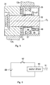
- Fig. 1 shows a medical device supporting apparatus according to a first embodiment of the present invention.
- a supporting base 10 is detachably attached to a mounting body 11 such as a floor or a bed. Arms 12a, 12b, 12c are joined to the supporting base 10 via joints 13a, 13b, 13c in sequence.
- a holding device 15 for mounting a medical device is attached to the distal arm 12a via a ball joint 14.
- the ball joint 14 can include an electromagnet (not shown), which has an electromagnetic brake built therein.
- the electromagnet (not shown) is electrically connected to a control box 16 which constitutes a control unit, and is driven under the control of the control box 16. In other words, the electromagnet (not shown) performs locking and unlocking of the position of the ball joint 14 according to presence or absence of electric distribution.
- an endoscope 17 is inserted into and supported by the holding device 15.
- the holding device 15 is provided with first and second switch levers 18, 19, which correspond to the final control elements, on both sides of the endoscope 17 so as to be operated in opposite directions.
- the first and second switch levers 18, 19 are rotatably supported via hinges 181, 191 at one end of each as shown in Fig. 2, and the proximal ends thereof are opposed to first and second micro switches 20, 21 disposed on the holding device 15.
- the first and second micro switches 20, 21 are electrically connected to the electromagnet (not shown) on the ball joint 14 and to electromagnets disposed on the joints 13a-13c, respectively (as discussed below).
- the first and second switch levers 18, 19 are attached to the holding device 15 at midsections thereof via a first and second spring members 182, 192, and are restored to the initial positions (OFF positions of first and second micro switches 20, 21) by biasing forces of the first and second spring members 182, 192.
- the first and second spring members 182, 192 are set to different spring constants Ka, Kb respectively, having a relation of Ka ⁇ Kb for example, and the amount of the operating force of the first and second switch levers 18, 19 are set based on the spring constants.
- a joint member 31 is rotatably attached to a housing 30 about an axis 02 via a joint shaft 32.
- the distal end of the arm 12a is attached to the housing 30, and the distal end of the arm 12b is attached to the other joint member 31.
- the joint member 31 is provided with a brake disk 33, and for example, an iron-made brake shoe 34 provided on the joint shaft 32 is opposed to the brake disk 33 so as to be capable of coming into and out of contact thereto.
- the brake shoe 34 is fitted into a key groove 321 provided on the joint shaft 32 so as to be capable of moving and is rotated about the axis 02 integrally with the joint shaft 32.
- the housing 30 is provided with a cam 301, such as a slot, and a pin 35 which constitutes a rotational force adjusting mechanism is operably inserted into the cam 301.
- the operating tab 35 is rotatably supported at the distal end thereof about the joint shaft 32 and the rotary axis 02, and when it is urged to rotate about the rotary axis 02, it is moved along the cam 301 to the position indicated by broken lines in Figs. 3A and 3B.
- a spring member 36 is engaged between the operating tab 35 and the brake shoe 34.
- the spring member 36 presses the brake shoe 34 against the brake disk 33 by its biasing force, and restricts the rotation of the joint member 31 by a frictional force generated at that time. Accordingly, when the operating tab 35 is moved along the cam 301, it varies the biasing force of the spring member 36 and varies a frictional force between the brake disk 33 and the brake shoe 34, so that the fixing force against the rotation of the joint member 31 is variably adjusted.
- the housing 30 is provided with an electromagnet 37 so as to oppose the brake shoe 34.
- the electromagnet 37 pulls the brake shoe 34 by an electromagnetic force against the biasing force of the spring member 36.
- the electromagnet 37 is electrically connected to the control box 16, and turns the second micro switch 21 ON in conjunction with the operation of the second switch lever 19.
- the brake shoe 34 is pulled to the position indicated by the broken line in Fig. 3B and releases locking state of the joint member 31 with respect to the housing 30. Accordingly, the joint 13a is locked in a state in which the electromagnet 37 is not energized, and is unlocked in a state in which the electromagnet 37 is energized.
- the operator operates the respective operating tabs 35 which are mounted to the respective joints 13a, 13b, 13c first to move a position shown by solid lines in Figs. 3A and 3B, where the biasing force of the spring member 36 becomes the maximum value.
- the locking force of the joints 13a, 13b, 13c are set to the maximum state.
- the first and second micro switches 20, 21 are both in the OFF state, and hence the brake shoe 34 is pressed against the brake disk 33 by the spring member 36, whereby the joints 13a, 13b, 13c are locked against rotation by its frictional force.
- the arms 12a, 12b, and 12c, and the supporting base 10 do not move with respect to each other.
- the ball joint 14 is also locked against movement in the same manner, and the arm 12a and the holding device 15 are set to the locked state in which they do not move with respect each other.
- the operator grips the holding device 15 and presses the first and second switch levers 18, 19. Then, the first and second micro switches 20, 21 are turned ON against the biasing forces of the spring members 182, 192, and its ON signal is supplied to the control box 16.
- the control box 16 supplies electric power to the respective electromagnets 37 of the joints 13a, 13b, 13c and the electromagnet (not shown) of the ball joint 14. Accordingly, the respective brake disks 33 of the joints 13a, 13b, 13c are moved to the position indicated by the broken line in Fig. 3B by the electromagnetic force of the electromagnet 37, and hence the frictional force between the brake disk 33 and the brake shoe 34 is removed, so that the locking against the rotation of the respective joints 13a, 13b, 13c is released.
- the first switch lever 18 having the smaller amount of operating force does not return and is supported by a finger, the holding device 15 does not move and is held at the initial position. Then, when the operator further loosens the grip of the holding device 15, the first switch lever 18 having the smaller amount of the operating force is restored to its initial position by the first spring member 182, whereby the first micro switch 20 is turned OFF.
- the control box 16 blocks the power supply to the electromagnet (not shown) of the ball joint 14. Consequently, the ball joint 14 is fixed and locked at its moved position, whereby the position setting of the endoscope 17 is completed.
- the operator rotates the operating tabs 35 of the respective joints 13a, 13b, 13c. Then the operating tab 35 is moved along the cam 301 to the position indicated by the broken lines in Figs. 3A and 3B. Accordingly, the biasing force of the spring member 36 is lowered, the contact pressure between the brake shoe 34 and the brake disk 33 is lowered, the frictional force therebetween is reduced, and the locking forces of the joints 13a, 13b, 13c are set so as to be capable of manual operation.
- the amount of locking force (frictional force) between the brake disk 33 and the brake shoe 34 is set to an extent in which the arms 12a, 12b, 12c do not move spontaneously, which is the amount of locking force in which the operator can move the joints 13a, 13b, 13c.
- the operator adjusts the movement of the arms 12a, 12b, 12c by a force larger than the amount of locking force, whereby the endoscope 17 at the holding device 15 can be withdrawn from the operative portion.
- the medical device supporting apparatus is configured in such a manner that the first and second switch levers 18, 19 having different amount of operating force are disposed correspondingly, and locking and unlocking of the arms 12a, 12b, 12c and the holding device 15 are performed in conjunction with the operation of the first and second switch levers 18, 19.
- the operator can recognize completion of operation reliably by the switching operation of the first and second switch levers 18, 19 being turned off in sequence according to the amount of operation thereof, and thus locking and unlocking operation of the endoscope 17 with high reliability and accuracy can be realized simply and easily.
- the second micro switch 21 having a larger amount of operating force is turned OFF first via the second switch lever 19, and the first switch lever 18 of the first micro switch 20 having smaller amount of operating force does not return, and hence it can be supported by a finger. Therefore, the holding device 15 does not move with respect to the arms 12a, 12b, 12c, and a desired visual field of the endoscope (or adjustment of a medical device) can be easily fixed.
- the operating tabs 35 for adjusting the locking force for the joints 13a, 13b, 13c respectively are adapted to be capable of being operable externally. In this arrangement, even when a failure such as disconnection of the cable or power outage happens during surgical operation, since the arms 12a, 12b, 12c can be moved easily by loosening the locking forces of the joints 13a, 13b, 13c by the operating tabs 35 during the surgical operation, movement of the endoscope 17 including retraction can easily be performed, whereby its handling property is improved.
- Fig. 4 and Fig. 5 show a medical device supporting apparatus according to the second embodiment of the invention, and include an emergency operating device in addition to the aforementioned first embodiment, which is expected to have the same effect as the first embodiment. Therefore, in Fig. 4 and Fig. 5, identical parts to Figs. 1 to 3 are represented by the identical numerals and detailed description will not be made.
- the endoscope 17 is detachably inserted into the holding device 15.
- first and second switch storage portions 151, 152 so as to oppose each other, and first and second micro switches 40, 41 are stored and disposed in the first and second switch storage portions 151, 152 so as to be operated in the opposite direction.
- the first and second micro switches 40, 41 are electrically connected to the control box 16.
- a switch lever 42 is rotatably provided in the first switch storage portion 151 via a hinge 421 so as to oppose the first micro switch 40, and a clockwise (the direction to turn ON the first micro switch 40) biasing force is exerted to the switch lever 42 via a first spring member 43.
- the proximal end of the first spring member 43 is adjustably engaged with the distal end of the operating force adjusting member 44.
- the operating force adjusting member 44 is supported at the midsection by the holding device 15 so as to be capable of screw-adjustment, and is operably provided with a final control element 441 at the proximal end so as to project from the holding device.
- the operating force adjusting member 44 is moved against the first spring member 43 by its rotating operation, and a biasing force of first spring member 43 is variably set to variably set the operating force of the switch lever 42. That is, the operating force adjusting member 44 is threadingly engaged with the holding device 15 such that it can be rotated to compress (and therefore preload) the first spring member 43.
- a recessed switch cover 45 is provided on the second switch storage portion 152 via a spring member 46 at the position opposing to the second micro switch 41 so as to be capable of pressing operation.
- the joints 13a, 13b, 13c can be configured as shown in Fig. 5, and a pressing force adjusting member 47 is engaged to the other end of the spring member 36 which is engaged with the brake shoe 34 at one end.
- the pressing force adjusting member 47 is disposed at the joint shaft 32 so as to be capable of moving in the axial direction, and an adjusting screw 48 is adjustably screwed at a predetermined position.
- the adjusting screw 48 is connected to the revolving shaft of a brake force adjusting drive motor 49 at a proximal end thereof, and when it is rotated by the drive motor 49, the pressing force adjusting member 47 is moved axially via the adjusting screw 48 according to the direction of rotation. Accordingly, the pressing force adjusting member 47 variably set a biasing force of the spring member 36 according to the moved position thereof to variably set the press-contact force between the brake shoe 34 and the brake disk 33.
- the drive motor 49 is connected to a motor driver 50 which constitutes the emergency operating device as shown in Fig. 6 via a wiring cable 51.
- the motor driver 50 is provided in the control box 16 for example, and is connected to power supply 53 via an emergency moving switch 52. Accordingly, when the emergency moving switch 52 in the control box 16 is turned ON, the motor driver 50 receives a supply of ON signal, and outputs a drive signal to the drive motor 49 in response to this ON signal to drive and control the drive motor 49.
- the pressing force adjusting member 47 is moved in the direction of 02 axis, the urging force of the spring member 36 is varied according to the moved position thereof, and the press-contact force between the brake shoe 34 and the brake disk 33 is adjusted.
- the urging force of the spring member 36 of the pressing force adjusting member 47 is the smallest in a state in which the pressing force adjusting member 47 is moved to the position shown by a broken line in Fig. 5 and accommodates a predetermined failure.
- the operator rotates the operating force adjusting member 44 before use, and varies the compression amount of the spring member 43 to adjust the amount of operating force of the switch lever 42 according to the taste of the operator, grips the holding device 15 so that his/her thumb is placed on the switch lever 42 and the first finger is placed to the switch cover 45 for pressing operation.
- the first and second micro switches 40, 41 are turned ON against the urging force of the spring members 43, 46, and the respective ON signal is supplied to the control box 16.
- the control box 16 supplies electric power to the electromagnets 37 of the joints 13a, 13b, 13c and the electromagnet (not shown) of the ball joint 14 of the holding device 15 which holds the endoscope 17, so that the respective joints 13a, 13b, 13c and the ball joint 14 are set to the rotatable state.
- the endoscope 17 is moved to a desired position in the operative portion, the visual field to be observed is fixed, and then, a force to grip the switch lever 42 and the switch cover 45 is loosened in the same manner to turn the first and second micro switches 40, 41 OFF in sequence, and the respective joints 13a, 13b, 13c and the holding device 15 are movably placed and fixed.
- the amount of operating force to turn the first micro switch 40 ON is set to a larger value than that of the second micro switch 41, a force of the thumb is loosened first to turn the first micro switch 40 to OFF.
- the switch cover 45 is not restored and is maintained in a state of being supported by the first finger, the holding device 15 is not moved.
- the emergency moving switch 52 of the control box 16 is pressed. Then, the ON signal of the emergency moving switch 52 is supplied to the motor driver 50.
- the motor driver 50 here drives the drive motors 49 provided in the respective joints 13a, 13b, 13c, and moves the pressing force adjusting member 47 to the position indicated by the broken line in Fig. 5 via the adjusting screw 48. Accordingly, the biasing force of the spring member 36 is reduced in comparison with the non-failure state, and a contact pressure force to press the brake disk 33 against the brake shoe 34 is set to a smaller value.
- the amount of locking force between the brake disk 33 and the brake shoe 34 is maintained in an extent in which the arms 12a, 12b, 12c are not moved spontaneously, but the operator can move the joints 13a, 13b, 13c.
- the operator moves the arms 12a, 12b, 12c by the amount of force larger than that for locking the joints 13a, 13b, 13c to withdraw the endoscope 17 supported by the holding device 15 from the operative poriton.
- the amount of operating force of the first micro switch 40 is adapted to be selectively variable, the amount of operating force can be set selectively according to the taste of the operator, and hence the handling property can be improved. Also, in this arrangement, even in the case of failure such as disconnection of an electric system such as a power supply system or power outage, the arms 12a, 12b, 12c themselves are prevented from moving spontaneously only by pressing the emergency moving switch 52 and, in addition, the locking force of joints 13a, 13b, 13c can be adjusted to an extent in which the operator can move the arms 12a, 12b, 12c. Therefore, quick support in the event of failure is achieved.
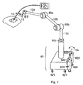
- Fig. 7 shows a medical device supporting apparatus according to the third embodiment of the present invention, which is expected to have the same effect as the first and second embodiments. Therefore, in Fig. 7, identical parts to Fig. 1 are represented by the identical numerals and detailed description will not be made.
- the aforementioned arms 12a, 12b, 12c are connected via a joint 60a, a joint 60b, and joint 60c, in which known fluid (pneumatic pressure) brakes are integrated, in sequence.
- the fluid brake is adapted to release the locking state of the brake when a pressure is applied.
- the holding device 15 is movable connected to the arm 12a via a ball joint 61 in which a fluid (pneumatic pressure) brake is integrated in the same manner.
- These fluid brakes are connected to a pneumatic pressure control device, described later, which is integrated in a carrier base 62 for supporting the arms 12a, 12b, 12c via piping (not shown).
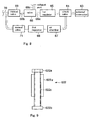
- the pneumatic pressure control device is configured in such a manner that a fluid pressure source, not shown, such as a gas cylinder provided in a surgical operation room, is connected to an external connector 63; as shown in Fig. 8, and an input end of a check valve 64 is connected to the external connector 63.
- the check valve 64 is connected at an output end to an electromagnetic valve 66 via a first regulator 65 for adjusting the pressure, and at the other output end to a second regulator 68 for adjusting the pressure via an air chamber 67.
- a first conduit line 66a When no input signal is supplied to the electromagnetic valve 66 a first conduit line 66a is closed, and a second conduit line 66b and a third conduit line 66c, which is in communication with an exhaust port are communicated, while in a state in which an input signal is supplied thereto, the second conduit line 66b and the first conduit line 66a are brought into communication. Then, the second conduit line 66b of the electromagnetic valve 66 is connected to a conduit line 70 via a first manual valve 69, and is connected to the fluid brakes integrated in the joints 60a, 60b, 60c via the conduit line 70.
- the second regulator 68 is connected to the second manual valve 71 to set fluid in the air chamber 67 at a pneumatic pressure providing the locking force to the airbrake to an extent that the arms 12a, 12b, 12c are not moved spontaneously, but may be moved manually by the operator, and output it to the conduit line 70 via the second manual valve 71.
- the carrier base 62 is provided with carrier wheels 621 at four corners thereof, and for example, two stoppers 622, 622 are rotatably provided about a rotary axis 04 via hinges 623, 623 at a predetermined distance corresponding to the carrier wheels 621.
- the stoppers 622, 622 are disposed so as to be selectively rotatable via detent device 624 (in Fig. 7, only one of them is shown as a matter of convenience of the drawing).
- the stoppers 622, 622 are provided with operating tabs 622a at the upper ends thereof as shown in Fig. 9, and with contact members 622b at the lower end thereof corresponding to the surface of installation such as a floor surface. Threaded portions 622c are provided at the midsection of the stopper 622, and the threaded portions 622c are attached to guiding members 622d so as to be adjustable by screwing. Accordingly, the stoppers 622, 622 are rotated by holding the operating tabs 622a by hand, so that the threaded portions 622c are moved in the vertical direction by being guided by the guiding members 622d.
- the aforementioned holding device 15 is provided with a known photo interrupter 72 instead of the second micro switch 41 in the second embodiment.
- the photo interrupter 72 has two contact points on the back side thereof, and is adapted in such a manner that the two contact points are electrically short circuited when being touched to detect contact with the operator's hand.
- the photo interrupter 72 and the first micro switch 40 of the holding device 15 are connected in series to a control circuit of the electromagnetic valve 66.
- the control circuit drives the electromagnetic valve 66 in a state in which the photo interrupter 72 and the first micro switch 40 are in the OFF state to supply air to the fluid brakes of the respective joints 60a, 60b, 60c, and the ball joint 61.
- an assistant or a nurse releases the detent device 624 of the stopper 622, and allows rotation about the rotary axis 04 via the hinge 623.
- whether the contact surface of the contact portion 622b of the stopper 622 which comes into contact with the floor is dirty is checked.
- the contact surface of the contact portion 622b is dirty, the contact surface is cleaned in order to secure the fixing force.
- the carrier base 62 is moved to a desired position using the carrier wheels 621, where the operating tab 622a of the stopper 622 is rotated to cause the contact portion 622b to be abutted against the floor.
- the carrier base 62 is positioned on the floor so as not to move when two of the carrier wheels 621 on the side of the stopper come apart from the floor.
- the operator grips the holding device 15 in order to move the holding device 15 to a desired position, his/her first finger and second finger touch the photo interrupter 72, and the photo interrupter 72 detects touch of the fingers.
- the operator presses the switch lever 42 with his/her thumb, and turns the first micro switch 40 ON.
- the electromagnetic valve 66 of the aforementioned pneumatic pressure control device is activated and air is supplied to the fluid brakes of the respective joints 60a, 60b, 60c and the fluid brake of the ball joint 61, so that the brakes of the respective joints 60a, 60b, 60c and the ball joint 61 are released.
- the holding device 15 when the holding device 15 is moved to a desired position, the operator loosens a force exerted by his/her thumb to turn the first micro switch 40 OFF. Then, the electromagnetic valve 66 closes the first conduit line 66a, and air supplied to the fluid brakes is discharged into the atmospheric air through the exhaust port from the third conduit line 66c, so that the brakes of the respective joints 60a, 60b, 60c and the ball joint 61 are fixed. In this case, although it takes slight time from the timing when the first micro switch 40 is turned OFF to the timing when the respective joints 60a, 60b, 60c and the ball joint 61 are fixed, the holding device 15 does not move because a gravitational force and a supporting force of his/her hand are in balance.
- the first manual valve 69 is closed first, and then the second manual valve 71 is opened to supply air to the fluid brakes. Consequently, the locking forces of the brakes of the respective joints 60a, 60b, 60c are such that the arms 12a, 12b, 12c do not move spontaneously, but the operator can move the arms 12a, 12b, 12c by hand. In this state, when the operator moves the arms 12a, 12b, 12c, the endoscope 17 of the holding device 15 is withdrawn from the operative portion.
- the respective joints 60a, 60b, 60c since there is no mechanisms for weakening the locking forces of the brakes provided in the respective joints 60a, 60b, 60c, the respective joints 60a, 60b, 60c can be reduced in size. Therefore, since the force of inertia caused by the mass of the joints can be reduced when moving the arms, operability is improved.
- the switching structure using the first micro switch 40 and the photo interrupter 72 since the switching structure using the first micro switch 40 and the photo interrupter 72 is employed, there is no switching error due to a reaction force of the first micro switch 40, and hence the switching operation is achieved with high degree of accuracy.
- the stopper 622 is rotatably provided on the carrier base 62, and the carrier base 62 is positioned and fixed by the stopper 622, a constantly high locking force is obtained by rotating the stopper 622 in the reverse direction for cleaning the contact portion 622b thereof.
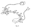
- Fig. 11 and Fig. 12 show a medical device supporting apparatus according to the fourth embodiment of the present invention, in which further preferable effects are expected in comparison with the first to third embodiments. Therefore, in Fig. 11 and Fig. 12, identical parts to Fig. 1 are represented by the identical numerals and detailed description will not be made.
- the distal portion of the arm 12a is attached to the holding unit 15, to which the endoscope 17 is detachably attached, on the lower side in the direction of a gravitational force (distal to an area of larger cross section 17a, e.g., a surface on a distal side of the endoscope) via a ball joint 80 so as to be capable of switching between the movable state and the locked state, and so as to be unbalanced with respect to the distal end of the arm 12a in the movable state.
- a gravitational force distal to an area of larger cross section 17a, e.g., a surface on a distal side of the endoscope
- the ball joint 80 is attached at the proximal end of a rod 801 to the grip member 81 of the holding device 15 on the lower side in the direction of a gravitational force, and the distal end of the rod 801 is provided with a spherical member 802.
- the spherical member 802 is stored in the spherical seat housing 803 so as to be capable of moving and being locked.
- a pressing member 804 is stored in the spherical seat housing 803 so as to be capable of moving in the directions indicated by arrows A, B against the spherical member 802.
- the pressing member 804 is exerted with a biasing force in the direction indicated by the arrow A via a spring member 805, and a disk member 807 formed of magnetic material is attached to the proximal end thereof via a rod 806.
- the disk member 807 is disposed so as to oppose an electromagnet 808 at a predetermined distance.
- the electromagnet 808 is connected to the control box 16 (see Fig. 11), and is driven and controlled via the control box 16.
- the electromagnet 808 moves the disk member 807 in the direction of the arrow B against the biasing force of the spring member 805, bringing the pressing member 804 away from the spherical member 802, setting the spherical member 802 in the spherical seat housing 803 so as to be capable of moving freely, and setting the distance between the arm 12a and the holding device 15 so as to be capable of moving.
- the electromagnet 808 allows the pressing member 804 to be biased and moved in the direction of the arrow A by the spring member 805. Accordingly, the pressing member 804 exerts a contact pressure against the spherical member 802 of the ball joint 80, and the ball joint 80 is positioned at the moved position, so that the arm 12a and the holding device 15 are fixed in position.
- the holding device 15 Assuming that the mass of the holding device 15 is J, the center of gravity thereof is G, and the length between the center of gravity G and the center position P of the ball joint 80 is L with the endoscope 17 inserted, the holding device 15 is assembled in an unbalanced state in which a moment load of U is generated with respect to the center position P depending on the mass J in a state in which the electromagnet 808 is driven and the spherical member is in a free state.
- the grip member 81 of the holding device 15 is provided with first and second switches 82, 83, which constitute a final control element of the input portion and are operated by different amounts of operating force, and are provided separately on the upper and lower ends in the direction of gravitational direction (corresponding to the direction of insertion of the endoscope 17) substantially parallel with each other.
- the first and second switches are electrically connected to the control box 16.
- the first switch 82 having a larger operating force is disposed on the upper side of the grip member 81 of the holding device 15, and, preferably, set to have the displacement of operation smaller than that of the second switch 83.
- the second witch 83 having the smaller operating force and, preferably, set to have a larger displacement in comparison with the first switch 82 is disposed on the lower side of the grip member 81 of the holding device 15.
- the amount of operating force of the second switch 83 is set to a value smaller than a dropping moment (LJ/M) caused by aforementioned unbalance of the holding device 15. Accordingly, for example, during operation in the locked state, as an operator 84 gradually reduces the gripping force, the second switch 83 located on the lower side with respect to the gravitational force is in the state of being pressed by the finger of the operator 84 by the aforementioned dropping moment (LJ/M), and hence the first switch 82 is absolutely turned OFF prior to the second switch 83. Therefore, the operability of the first and second switches 82, 83 is enhanced, and hence adjustment of movement of the holding device 15 can be performed with a higher degree of accuracy.
- LJ/M dropping moment
- the effect obtained by setting the amount of operation of the first switch 82 is set to a smaller value than the amount of operation of the second switch 83 will be described.
- the first switch 82 of the smaller amount of operation is immediately turned OFF, and thereafter, the second switch 83 is turned OFF, whereby the locking operation of the holding device 15 is completed. Therefore, by setting the amount of operation of the first switch 82 to a value as small as possible, the speed of turning-OFF operation of the first switch 82 is increased, and hence the speed-up of the locking operation is promoted.
- the control box 16 opens the spherical member 802 so as to be capable of moving with respect to the spherical seat housing 803 by driving the electromagnet 808 and attracting the pressing member 804 in the direction of the arrow B against the urging force of the spring member 805.
- the holding device 15 is capable of moving three-dimensionally with respect to the arm 12a, and moves the endoscope 17, which is inserted into the body cavity for example through an opening provided on the surface of the patient's body, in a desired position.
- the operator 84 loosens his/her hand, which is gripping the grip member 81 of the holding device 15.
- the second switch 83 of the grip member 81 of the holding device 15 is released by the amount of operating force smaller than LJ/M, because the second switch 83 is in a state in which the moment load of LJ/M is provided to the operating portion S by the mass of the holding device 15 including the endoscope 17 as described above.
- the control box 16 stops driving the electromagnet 808. Then, the pressing member 804 of the ball joint 80 is urged in the direction of the arrow A by an urging force of the spring member 805 and is brought into press-contact with the spherical member 802, whereby the spherical member 802 is positioned with respect to the spherical seat housing 803, so that the holding device 15 is positioned and locked with respect to the arm 12a.
- the lower side in the direction of gravitational force of the holding device 15, which holds the endoscope 17, is assembled to the arm 12a, which is provided so as to be capable of moving and locking three-dimensionally, via the ball joint 80, which is capable of moving and locking, to dispose the holding device 15 in the unbalanced manner in a movable state, and the first and second switches 82, 83 operated by different amount of operating force are provided on both sides of the grip member 81 of the holding device 15 in the direction of the gravitational force of the holding device 15.
- the holding device 15 since the holding device 15 is in the unbalanced state in a state in which the endoscope 17 is moved to a desired position by gripping the grip member 81 of the holding device 15 and moving the same with respect to the arm 12a, as the operator 84, griping the grip member 81 so as to prevent from dropping, loosens the gripping force gradually, the first switch 82 is consequently released first, then the second switch 83 is subsequently released. Therefore, the distal end of the endoscope 17 inserted into the holding device 15 is prevented from being displaced, and accurate positioning and locking at a desired position are achieved.
- the unbalanced structure in which the lower side in the direction of the gravitational force of the holding device 15 according to the fourth embodiment is assembled to the arm 12a so as to be capable of moving and locking via the ball joint 80, and in this movable state, the holding device 15 is supported in the unbalanced manner with respect to the arm 12a is also applicable to the first to third embodiments described above, and substantially the same effect can be expected.
- the endoscope is used as the medical device
- it is not limited thereto, and may be used as a supporting structure for the medical device including various treatment devices, and substantially the same effect can be expected.
Landscapes
- Health & Medical Sciences (AREA)
- Life Sciences & Earth Sciences (AREA)
- Surgery (AREA)
- General Health & Medical Sciences (AREA)
- Public Health (AREA)
- Veterinary Medicine (AREA)
- Pathology (AREA)
- Nuclear Medicine, Radiotherapy & Molecular Imaging (AREA)
- Animal Behavior & Ethology (AREA)
- Engineering & Computer Science (AREA)
- Biomedical Technology (AREA)
- Heart & Thoracic Surgery (AREA)
- Medical Informatics (AREA)
- Molecular Biology (AREA)
- Biophysics (AREA)
- Physics & Mathematics (AREA)
- Radiology & Medical Imaging (AREA)
- Optics & Photonics (AREA)
- Oral & Maxillofacial Surgery (AREA)
- Endoscopes (AREA)
- Manipulator (AREA)
Applications Claiming Priority (4)
| Application Number | Priority Date | Filing Date | Title |
|---|---|---|---|
| JP2003345995 | 2003-10-03 | ||
| JP2003345995 | 2003-10-03 | ||
| JP2004036663 | 2004-02-13 | ||
| JP2004036663A JP4559093B2 (ja) | 2003-10-03 | 2004-02-13 | 医療用具支持装置 |
Publications (3)
| Publication Number | Publication Date |
|---|---|
| EP1520548A2 true EP1520548A2 (de) | 2005-04-06 |
| EP1520548A3 EP1520548A3 (de) | 2005-05-04 |
| EP1520548B1 EP1520548B1 (de) | 2006-11-22 |
Family
ID=34315741
Family Applications (1)
| Application Number | Title | Priority Date | Filing Date |
|---|---|---|---|
| EP04023372A Expired - Lifetime EP1520548B1 (de) | 2003-10-03 | 2004-09-30 | Stützgerät für chirurgische Instrumente |
Country Status (4)
| Country | Link |
|---|---|
| US (1) | US20050075536A1 (de) |
| EP (1) | EP1520548B1 (de) |
| JP (1) | JP4559093B2 (de) |
| DE (1) | DE602004003318T2 (de) |
Cited By (22)
| Publication number | Priority date | Publication date | Assignee | Title |
|---|---|---|---|---|
| WO2007005757A3 (en) * | 2005-07-01 | 2007-05-18 | Hansen Medical Inc | Support assembly for robotic catheter system |
| EP1790290A3 (de) * | 2005-11-28 | 2007-07-18 | Cefla Societa' Cooperativa | Einheit zur Erfassung von dentalen Röntgenbildern |
| WO2008040537A1 (en) * | 2006-10-06 | 2008-04-10 | Helmut Fricke | Lockable joint |
| WO2008125870A3 (en) * | 2007-04-11 | 2009-07-23 | Forth Photonics Ltd | A supporting structure and a workstation incorporating the supporting structure for improving, objectifying and documenting in vivo examinations of the uterus |
| US7963288B2 (en) | 2005-05-03 | 2011-06-21 | Hansen Medical, Inc. | Robotic catheter system |
| WO2012007168A1 (de) * | 2010-07-15 | 2012-01-19 | Sensodrive Gmbh | Haltevorrichtung für ein instrument |
| WO2012110316A1 (de) * | 2011-02-18 | 2012-08-23 | Siemens Aktiengesellschaft | Gelenkarm mit arretierfunktion |
| WO2012127116A3 (en) * | 2011-03-21 | 2013-01-17 | Planmeca Oy | Arm structure for an intra-oral x-ray device |
| WO2013045645A1 (fr) * | 2011-09-30 | 2013-04-04 | Universite Pierre Et Marie Curie (Paris 6) | Dispositif de guidage d'un instrument medical insere dans une voie naturelle ou une voie artificielle d'un patient |
| CN103892922A (zh) * | 2014-04-08 | 2014-07-02 | 合肥德铭电子有限公司 | 用于微创手术的气动臂持物端快速泄压调节装置 |
| EP2026699A4 (de) * | 2006-06-01 | 2015-01-21 | Surgical Concept Designs Llc | Mehrgelenk-fixationssystem |
| CN104983468A (zh) * | 2015-07-24 | 2015-10-21 | 绵阳美科电子设备有限责任公司 | 一种腔镜操作手机器手手臂及其操作方法 |
| WO2016132689A1 (en) * | 2015-02-18 | 2016-08-25 | Sony Corporation | Medical support arm device and medical system |
| WO2016156210A1 (de) * | 2015-03-27 | 2016-10-06 | Medineering Gmbh | Haltearm für medizinische zwecke mit abnehmbarer bedieneinrichtung, sowie bedieneinrichtung hierfür |
| WO2016156201A1 (de) * | 2015-03-27 | 2016-10-06 | Medineering Gmbh | Chirurgisches instrument, system, haltearm sowie verfahren |
| WO2016156168A1 (de) * | 2015-03-27 | 2016-10-06 | Medineering Gmbh | Verfahren und vorrichtung zum steuern eines chirurgischen mechatronischen assistenzsystems mittels eines haltearms für medizinische zwecke |
| CN106901835A (zh) * | 2017-03-15 | 2017-06-30 | 哈尔滨工业大学 | 一种具有位置保持功能的五自由度主手 |
| US10357330B2 (en) | 2015-02-18 | 2019-07-23 | Sony Corporation | Medical support arm device and medical system |
| US10556092B2 (en) | 2013-03-14 | 2020-02-11 | Auris Health, Inc. | Active drives for robotic catheter manipulators |
| US10555786B2 (en) | 2015-02-26 | 2020-02-11 | Olympus Corporation | Operation input device and medical manipulator system |
| EP3167838B1 (de) * | 2015-11-13 | 2021-02-17 | Ondal Medical Systems GmbH | Drehbare verbindung mit einem bremsungsmechanismus |
| US11906009B2 (en) | 2021-07-30 | 2024-02-20 | Corindus, Inc. | Rotational joint assembly for robotic medical system |
Families Citing this family (31)
| Publication number | Priority date | Publication date | Assignee | Title |
|---|---|---|---|---|
| CA2437286C (en) | 2002-08-13 | 2008-04-29 | Garnette Roy Sutherland | Microsurgical robot system |
| US7930065B2 (en) | 2005-12-30 | 2011-04-19 | Intuitive Surgical Operations, Inc. | Robotic surgery system including position sensors using fiber bragg gratings |
| US9962066B2 (en) | 2005-12-30 | 2018-05-08 | Intuitive Surgical Operations, Inc. | Methods and apparatus to shape flexible entry guides for minimally invasive surgery |
| US20080064927A1 (en) * | 2006-06-13 | 2008-03-13 | Intuitive Surgical, Inc. | Minimally invasrive surgery guide tube |
| US7832114B2 (en) * | 2007-04-04 | 2010-11-16 | Eigen, Llc | Tracker holder assembly |
| US9096033B2 (en) | 2007-06-13 | 2015-08-04 | Intuitive Surgical Operations, Inc. | Surgical system instrument sterile adapter |
| US20090227874A1 (en) * | 2007-11-09 | 2009-09-10 | Eigen, Inc. | Holder assembly for a medical imaging instrument |
| CN101194848B (zh) * | 2008-01-09 | 2010-04-21 | 北京航空航天大学 | 执行器末端快速切换装置 |
| JP5004895B2 (ja) * | 2008-07-31 | 2012-08-22 | 清 田中 | 指圧装置 |
| JP2012095679A (ja) * | 2009-01-27 | 2012-05-24 | Mitaka Koki Co Ltd | 医療用器具の伸縮式保持アーム装置 |
| US8747309B2 (en) | 2010-11-09 | 2014-06-10 | Covidien Lp | Suspension system for minimally invasive surgery |
| US8870759B2 (en) * | 2009-12-04 | 2014-10-28 | Covidien Lp | Suspension system for minimally invasive surgery |
| JP5590983B2 (ja) * | 2010-06-15 | 2014-09-17 | オリンパスメディカルシステムズ株式会社 | 医療器具保持装置 |
| DE102011004926A1 (de) * | 2011-03-01 | 2012-09-06 | Karl Storz Gmbh & Co. Kg | Einstellbare Haltevorrichtung für ein Endoskop |
| EP2852769A1 (de) * | 2012-05-21 | 2015-04-01 | Güdel Group AG | Kugelgelenk |
| DE102013005999A1 (de) * | 2013-04-09 | 2014-10-09 | Carl Zeiss Microscopy Gmbh | Schwenkarmstativ für Digitalmikroskope |
| EP3119314B1 (de) | 2014-03-17 | 2020-05-06 | Intuitive Surgical Operations, Inc. | System und verfahren zur lösbaren kupplung in einem gelenkarm |
| TWI554372B (zh) * | 2014-06-23 | 2016-10-21 | Hiwin Tech Corp | Surgical instrument height adjustment link device |
| CA2966837C (en) * | 2014-11-14 | 2023-03-28 | Medineering Gmbh | Intelligent holding arm for head surgery, with touch-sensitive operation |
| EP3061494A1 (de) | 2015-02-27 | 2016-08-31 | Nihon Kohden Corporation | Verbindungsmechanismus für armteil |
| JP6454180B2 (ja) * | 2015-02-27 | 2019-01-16 | 日本光電工業株式会社 | 磁気刺激コイルの着脱装置 |
| US10849650B2 (en) | 2015-07-07 | 2020-12-01 | Eigen Health Services, Llc | Transperineal needle guidance |
| US10716544B2 (en) | 2015-10-08 | 2020-07-21 | Zmk Medical Technologies Inc. | System for 3D multi-parametric ultrasound imaging |
| USD914207S1 (en) * | 2018-01-03 | 2021-03-23 | Karl Storz Se & Co. Kg | Instrument holding device for surgery |
| CN108742489A (zh) * | 2018-06-13 | 2018-11-06 | 河南科技大学第附属医院 | 一种电子喉镜支架 |
| WO2020115881A1 (ja) * | 2018-12-06 | 2020-06-11 | オリンパス株式会社 | 保持装置 |
| ES2956108T3 (es) * | 2019-09-25 | 2023-12-13 | Ovesco Endoscopy Ag | Sistema de cápsula endoscópica con retroalimentación háptica |
| DE102020122352A1 (de) | 2020-08-26 | 2022-03-03 | Isys Medizintechnik Gmbh | Motorisierter Positionierarm |
| CN113892893B (zh) * | 2021-12-09 | 2022-06-21 | 深圳市宏济医疗技术开发有限公司 | 一种耳鼻喉内窥镜支架 |
| CN114179121B (zh) | 2021-12-23 | 2025-05-27 | 北京罗森博特科技有限公司 | 一种机械臂 |
| KR102943273B1 (ko) | 2023-11-08 | 2026-03-25 | 부산대학교 산학협력단 | 원터치 고정해제 방식의 의료용 클램프 |
Citations (1)
| Publication number | Priority date | Publication date | Assignee | Title |
|---|---|---|---|---|
| JP2002345831A (ja) | 2001-05-22 | 2002-12-03 | Olympus Optical Co Ltd | 手術機器保持装置 |
Family Cites Families (19)
| Publication number | Priority date | Publication date | Assignee | Title |
|---|---|---|---|---|
| US4863133A (en) * | 1987-05-26 | 1989-09-05 | Leonard Medical | Arm device for adjustable positioning of a medical instrument or the like |
| US5271384A (en) * | 1989-09-01 | 1993-12-21 | Mcewen James A | Powered surgical retractor |
| US5039254A (en) * | 1989-12-14 | 1991-08-13 | Science Applications International Corporation | Passive grabbing apparatus having six degrees of freedom and single command control |
| JPH03253810A (ja) * | 1990-03-05 | 1991-11-12 | Olympus Optical Co Ltd | 手術用顕微鏡の鏡体部位置調整制御装置 |
| US5597146A (en) * | 1991-08-05 | 1997-01-28 | Putman; J. Michael | Rail-mounted stabilizer for surgical instrument |
| US5394069A (en) * | 1993-03-08 | 1995-02-28 | International Business Machines Corporation | Mechanical brake hold circuit for an electric motor |
| JP2002191545A (ja) * | 1993-12-22 | 2002-07-09 | Olympus Optical Co Ltd | 手術器具保持装置 |
| JP2843507B2 (ja) * | 1994-08-09 | 1999-01-06 | 三鷹光器株式会社 | 関節式器具保持アーム |
| US5898424A (en) * | 1996-09-30 | 1999-04-27 | Gateway 2000, Inc. | Pointing device with differing actuation forces for primary and secondary buttons |
| JPH10262987A (ja) * | 1997-03-24 | 1998-10-06 | Olympus Optical Co Ltd | 手術器具保持装置 |
| JPH10277054A (ja) * | 1997-04-08 | 1998-10-20 | Olympus Optical Co Ltd | 手術用器具保持装置 |
| US5779209A (en) * | 1997-06-02 | 1998-07-14 | Robert G. Johnston | Positioning unit |
| US6246200B1 (en) * | 1998-08-04 | 2001-06-12 | Intuitive Surgical, Inc. | Manipulator positioning linkage for robotic surgery |
| US6852107B2 (en) * | 2002-01-16 | 2005-02-08 | Computer Motion, Inc. | Minimally invasive surgical training using robotics and tele-collaboration |
| US6309397B1 (en) * | 1999-12-02 | 2001-10-30 | Sri International | Accessories for minimally invasive robotic surgery and methods |
| JP4354043B2 (ja) * | 1999-05-10 | 2009-10-28 | オリンパス株式会社 | 内視鏡保持具 |
| JP2001357758A (ja) * | 2000-06-12 | 2001-12-26 | Alps Electric Co Ltd | 複合操作型入力装置 |
| US6587750B2 (en) * | 2001-09-25 | 2003-07-01 | Intuitive Surgical, Inc. | Removable infinite roll master grip handle and touch sensor for robotic surgery |
| US6793653B2 (en) * | 2001-12-08 | 2004-09-21 | Computer Motion, Inc. | Multifunctional handle for a medical robotic system |
-
2004
- 2004-02-13 JP JP2004036663A patent/JP4559093B2/ja not_active Expired - Fee Related
- 2004-09-30 EP EP04023372A patent/EP1520548B1/de not_active Expired - Lifetime
- 2004-09-30 DE DE602004003318T patent/DE602004003318T2/de not_active Expired - Lifetime
- 2004-10-04 US US10/958,138 patent/US20050075536A1/en not_active Abandoned
Patent Citations (1)
| Publication number | Priority date | Publication date | Assignee | Title |
|---|---|---|---|---|
| JP2002345831A (ja) | 2001-05-22 | 2002-12-03 | Olympus Optical Co Ltd | 手術機器保持装置 |
Cited By (39)
| Publication number | Priority date | Publication date | Assignee | Title |
|---|---|---|---|---|
| US7789874B2 (en) | 2005-05-03 | 2010-09-07 | Hansen Medical, Inc. | Support assembly for robotic catheter system |
| US7963288B2 (en) | 2005-05-03 | 2011-06-21 | Hansen Medical, Inc. | Robotic catheter system |
| US8968333B2 (en) | 2005-05-03 | 2015-03-03 | Hansen Medical, Inc. | Support assembly for robotic catheter system |
| WO2007005757A3 (en) * | 2005-07-01 | 2007-05-18 | Hansen Medical Inc | Support assembly for robotic catheter system |
| EP1790290A3 (de) * | 2005-11-28 | 2007-07-18 | Cefla Societa' Cooperativa | Einheit zur Erfassung von dentalen Röntgenbildern |
| US7429130B2 (en) | 2005-11-28 | 2008-09-30 | Cefla Societa Cooperative | Unit for acquiring dental radiographic images |
| EP2026699A4 (de) * | 2006-06-01 | 2015-01-21 | Surgical Concept Designs Llc | Mehrgelenk-fixationssystem |
| AU2007304428B2 (en) * | 2006-10-06 | 2013-03-21 | Orion Surgical Gmbh | Lockable joint |
| WO2008040537A1 (en) * | 2006-10-06 | 2008-04-10 | Helmut Fricke | Lockable joint |
| CN101522129B (zh) * | 2006-10-06 | 2012-11-07 | H·弗里克 | 可锁紧的接头及组件、手术牵开器支架、接头固定方法 |
| WO2008125870A3 (en) * | 2007-04-11 | 2009-07-23 | Forth Photonics Ltd | A supporting structure and a workstation incorporating the supporting structure for improving, objectifying and documenting in vivo examinations of the uterus |
| US10350023B2 (en) | 2010-07-15 | 2019-07-16 | Sensodrive Gmbh | Retaining device for an instrument |
| US9366285B2 (en) | 2010-07-15 | 2016-06-14 | Sensodrive Gmbh | Retaining device for an instrument |
| EP2593707B1 (de) | 2010-07-15 | 2018-10-17 | SENSODRIVE GmbH | Haltevorrichtung für ein instrument |
| WO2012007168A1 (de) * | 2010-07-15 | 2012-01-19 | Sensodrive Gmbh | Haltevorrichtung für ein instrument |
| WO2012110316A1 (de) * | 2011-02-18 | 2012-08-23 | Siemens Aktiengesellschaft | Gelenkarm mit arretierfunktion |
| CN103501705A (zh) * | 2011-03-21 | 2014-01-08 | 普兰梅卡有限公司 | 用于口腔内x射线装置的臂结构 |
| WO2012127116A3 (en) * | 2011-03-21 | 2013-01-17 | Planmeca Oy | Arm structure for an intra-oral x-ray device |
| US9622716B2 (en) | 2011-03-21 | 2017-04-18 | Planmeca Oy | Arm structure for intra-oral X-ray device |
| US9895197B2 (en) | 2011-09-30 | 2018-02-20 | Universite Pierre Et Marie Curie (Paris 6) | Device for guiding a medical instrument inserted into a natural duct or an artificial duct of a patient |
| FR2980683A1 (fr) * | 2011-09-30 | 2013-04-05 | Univ Paris Curie | Dispositif de guidage d'un instrument medical insere dans une voie naturelle ou une voie artificielle d'un patient |
| WO2013045645A1 (fr) * | 2011-09-30 | 2013-04-04 | Universite Pierre Et Marie Curie (Paris 6) | Dispositif de guidage d'un instrument medical insere dans une voie naturelle ou une voie artificielle d'un patient |
| US10556092B2 (en) | 2013-03-14 | 2020-02-11 | Auris Health, Inc. | Active drives for robotic catheter manipulators |
| CN103892922B (zh) * | 2014-04-08 | 2016-08-17 | 合肥德铭电子有限公司 | 用于微创手术的气动臂持物端快速泄压调节装置 |
| CN103892922A (zh) * | 2014-04-08 | 2014-07-02 | 合肥德铭电子有限公司 | 用于微创手术的气动臂持物端快速泄压调节装置 |
| WO2016132689A1 (en) * | 2015-02-18 | 2016-08-25 | Sony Corporation | Medical support arm device and medical system |
| US10898293B2 (en) | 2015-02-18 | 2021-01-26 | Sony Corporation | Medical support arm device and medical system |
| US10357330B2 (en) | 2015-02-18 | 2019-07-23 | Sony Corporation | Medical support arm device and medical system |
| US10555786B2 (en) | 2015-02-26 | 2020-02-11 | Olympus Corporation | Operation input device and medical manipulator system |
| WO2016156168A1 (de) * | 2015-03-27 | 2016-10-06 | Medineering Gmbh | Verfahren und vorrichtung zum steuern eines chirurgischen mechatronischen assistenzsystems mittels eines haltearms für medizinische zwecke |
| WO2016156201A1 (de) * | 2015-03-27 | 2016-10-06 | Medineering Gmbh | Chirurgisches instrument, system, haltearm sowie verfahren |
| WO2016156210A1 (de) * | 2015-03-27 | 2016-10-06 | Medineering Gmbh | Haltearm für medizinische zwecke mit abnehmbarer bedieneinrichtung, sowie bedieneinrichtung hierfür |
| EP3273898B1 (de) * | 2015-03-27 | 2021-02-24 | medineering GmbH | Chirurgisches instrument sowie system |
| US10993777B2 (en) | 2015-03-27 | 2021-05-04 | Brainlab Robotics Gmbh | Method and apparatus for controlling a surgical mechatronic assistance system by means of a holding arm for medical purposes |
| CN104983468A (zh) * | 2015-07-24 | 2015-10-21 | 绵阳美科电子设备有限责任公司 | 一种腔镜操作手机器手手臂及其操作方法 |
| EP3167838B1 (de) * | 2015-11-13 | 2021-02-17 | Ondal Medical Systems GmbH | Drehbare verbindung mit einem bremsungsmechanismus |
| CN106901835A (zh) * | 2017-03-15 | 2017-06-30 | 哈尔滨工业大学 | 一种具有位置保持功能的五自由度主手 |
| US11906009B2 (en) | 2021-07-30 | 2024-02-20 | Corindus, Inc. | Rotational joint assembly for robotic medical system |
| US12215750B2 (en) | 2021-07-30 | 2025-02-04 | Siemens Healthineers Endovascular Robotics, Inc | Rotational joint assembly for robotic medical system |
Also Published As
| Publication number | Publication date |
|---|---|
| JP2005125056A (ja) | 2005-05-19 |
| US20050075536A1 (en) | 2005-04-07 |
| EP1520548B1 (de) | 2006-11-22 |
| JP4559093B2 (ja) | 2010-10-06 |
| DE602004003318D1 (de) | 2007-01-04 |
| EP1520548A3 (de) | 2005-05-04 |
| DE602004003318T2 (de) | 2007-03-08 |
Similar Documents
| Publication | Publication Date | Title |
|---|---|---|
| EP1520548B1 (de) | Stützgerät für chirurgische Instrumente | |
| CN114423366B (zh) | 混合、直接控制和机器人辅助的手术系统 | |
| JP4472365B2 (ja) | 医療器具保持装置 | |
| EP1962711B1 (de) | Instrumentenschnittstelle eines roboter-chirurgiesystems | |
| CN113288431B (zh) | 锁定装置、手术器械、无菌板组件、动力盒及机器人系统 | |
| US8529582B2 (en) | Instrument interface of a robotic surgical system | |
| JP7772435B2 (ja) | ガイドワイヤカテーテル伝送装置 | |
| WO2018053305A1 (en) | Computer-assisted tele-operated surgery systems and methods | |
| US11357528B2 (en) | Apparatus for removably receiving an end effector for performing surgical operations | |
| US20230031403A1 (en) | Robotic surgical assemblies | |
| CN118787457B (zh) | 套管适配器、患者手术平台及手术机器人 | |
| CN115867220B (zh) | 机器人外科系统 | |
| JP4455088B2 (ja) | 医療機器保持装置 | |
| US20250387180A1 (en) | Surgical robotic instrument exchange | |
| JP7360761B1 (ja) | 手術支援装置 | |
| CN218979205U (zh) | 输入装置、主操作设备和手术机器人 | |
| CN118750161A (zh) | 一种磁牵引术野暴露系统自平衡机械臂及手术牵拉装置 | |
| KR20230079167A (ko) | 수술 로봇 아암을 도킹하기 위한 시스템 및 방법 |
Legal Events
| Date | Code | Title | Description |
|---|---|---|---|
| PUAI | Public reference made under article 153(3) epc to a published international application that has entered the european phase |
Free format text: ORIGINAL CODE: 0009012 |
|
| PUAL | Search report despatched |
Free format text: ORIGINAL CODE: 0009013 |
|
| AK | Designated contracting states |
Kind code of ref document: A2 Designated state(s): AT BE BG CH CY CZ DE DK EE ES FI FR GB GR HU IE IT LI LU MC NL PL PT RO SE SI SK TR |
|
| AX | Request for extension of the european patent |
Extension state: AL HR LT LV MK |
|
| AK | Designated contracting states |
Kind code of ref document: A3 Designated state(s): AT BE BG CH CY CZ DE DK EE ES FI FR GB GR HU IE IT LI LU MC NL PL PT RO SE SI SK TR |
|
| AX | Request for extension of the european patent |
Extension state: AL HR LT LV MK |
|
| 17P | Request for examination filed |
Effective date: 20050530 |
|
| AKX | Designation fees paid |
Designated state(s): DE FR GB |
|
| GRAP | Despatch of communication of intention to grant a patent |
Free format text: ORIGINAL CODE: EPIDOSNIGR1 |
|
| GRAS | Grant fee paid |
Free format text: ORIGINAL CODE: EPIDOSNIGR3 |
|
| 17Q | First examination report despatched |
Effective date: 20050928 |
|
| GRAA | (expected) grant |
Free format text: ORIGINAL CODE: 0009210 |
|
| AK | Designated contracting states |
Kind code of ref document: B1 Designated state(s): DE FR GB |
|
| REG | Reference to a national code |
Ref country code: GB Ref legal event code: FG4D |
|
| REF | Corresponds to: |
Ref document number: 602004003318 Country of ref document: DE Date of ref document: 20070104 Kind code of ref document: P |
|
| ET | Fr: translation filed | ||
| PLBE | No opposition filed within time limit |
Free format text: ORIGINAL CODE: 0009261 |
|
| STAA | Information on the status of an ep patent application or granted ep patent |
Free format text: STATUS: NO OPPOSITION FILED WITHIN TIME LIMIT |
|
| 26N | No opposition filed |
Effective date: 20070823 |
|
| PGFP | Annual fee paid to national office [announced via postgrant information from national office to epo] |
Ref country code: GB Payment date: 20140924 Year of fee payment: 11 |
|
| PGFP | Annual fee paid to national office [announced via postgrant information from national office to epo] |
Ref country code: FR Payment date: 20140906 Year of fee payment: 11 |
|
| GBPC | Gb: european patent ceased through non-payment of renewal fee |
Effective date: 20150930 |
|
| REG | Reference to a national code |
Ref country code: FR Ref legal event code: ST Effective date: 20160531 |
|
| PG25 | Lapsed in a contracting state [announced via postgrant information from national office to epo] |
Ref country code: GB Free format text: LAPSE BECAUSE OF NON-PAYMENT OF DUE FEES Effective date: 20150930 |
|
| PG25 | Lapsed in a contracting state [announced via postgrant information from national office to epo] |
Ref country code: FR Free format text: LAPSE BECAUSE OF NON-PAYMENT OF DUE FEES Effective date: 20150930 |
|
| P01 | Opt-out of the competence of the unified patent court (upc) registered |
Effective date: 20230528 |
|
| PGFP | Annual fee paid to national office [announced via postgrant information from national office to epo] |
Ref country code: DE Payment date: 20230920 Year of fee payment: 20 |
|
| REG | Reference to a national code |
Ref country code: DE Ref legal event code: R071 Ref document number: 602004003318 Country of ref document: DE |