EP1519095B1 - Schlauchbefestigungsanordnung und dafür verwendete Befestigungselement - Google Patents
Schlauchbefestigungsanordnung und dafür verwendete Befestigungselement Download PDFInfo
- Publication number
- EP1519095B1 EP1519095B1 EP04255980.7A EP04255980A EP1519095B1 EP 1519095 B1 EP1519095 B1 EP 1519095B1 EP 04255980 A EP04255980 A EP 04255980A EP 1519095 B1 EP1519095 B1 EP 1519095B1
- Authority
- EP
- European Patent Office
- Prior art keywords
- tube
- fixing member
- holder
- hole
- grippers
- Prior art date
- Legal status (The legal status is an assumption and is not a legal conclusion. Google has not performed a legal analysis and makes no representation as to the accuracy of the status listed.)
- Expired - Lifetime
Links
- 238000003780 insertion Methods 0.000 claims description 17
- 230000037431 insertion Effects 0.000 claims description 17
- 239000002184 metal Substances 0.000 claims description 5
- 239000000463 material Substances 0.000 claims description 4
- 230000007423 decrease Effects 0.000 claims description 3
- 230000004048 modification Effects 0.000 description 35
- 238000012986 modification Methods 0.000 description 35
- 239000000976 ink Substances 0.000 description 34
- 229920005989 resin Polymers 0.000 description 9
- 239000011347 resin Substances 0.000 description 9
- 238000000034 method Methods 0.000 description 6
- 229930040373 Paraformaldehyde Natural products 0.000 description 4
- 230000003247 decreasing effect Effects 0.000 description 4
- 229920006324 polyoxymethylene Polymers 0.000 description 4
- 230000003252 repetitive effect Effects 0.000 description 4
- 239000000853 adhesive Substances 0.000 description 3
- 230000001070 adhesive effect Effects 0.000 description 3
- 230000004323 axial length Effects 0.000 description 3
- 238000005452 bending Methods 0.000 description 3
- 230000008901 benefit Effects 0.000 description 3
- 238000010276 construction Methods 0.000 description 3
- 239000004033 plastic Substances 0.000 description 3
- 229920003023 plastic Polymers 0.000 description 3
- 230000008569 process Effects 0.000 description 3
- 229920002379 silicone rubber Polymers 0.000 description 3
- 239000004945 silicone rubber Substances 0.000 description 3
- 229910000639 Spring steel Inorganic materials 0.000 description 2
- 238000005336 cracking Methods 0.000 description 2
- 230000000694 effects Effects 0.000 description 2
- 230000035699 permeability Effects 0.000 description 2
- -1 polypropylene Polymers 0.000 description 2
- 230000008016 vaporization Effects 0.000 description 2
- 238000009834 vaporization Methods 0.000 description 2
- JOYRKODLDBILNP-UHFFFAOYSA-N Ethyl urethane Chemical compound CCOC(N)=O JOYRKODLDBILNP-UHFFFAOYSA-N 0.000 description 1
- 239000004677 Nylon Substances 0.000 description 1
- 239000004743 Polypropylene Substances 0.000 description 1
- 229910000831 Steel Inorganic materials 0.000 description 1
- 230000004888 barrier function Effects 0.000 description 1
- 229920005549 butyl rubber Polymers 0.000 description 1
- 239000003086 colorant Substances 0.000 description 1
- 230000000295 complement effect Effects 0.000 description 1
- 239000013013 elastic material Substances 0.000 description 1
- 239000004715 ethylene vinyl alcohol Substances 0.000 description 1
- 239000011888 foil Substances 0.000 description 1
- 229920001903 high density polyethylene Polymers 0.000 description 1
- 239000004700 high-density polyethylene Substances 0.000 description 1
- 239000007788 liquid Substances 0.000 description 1
- 229920001778 nylon Polymers 0.000 description 1
- 230000002093 peripheral effect Effects 0.000 description 1
- 229920000728 polyester Polymers 0.000 description 1
- 229920001155 polypropylene Polymers 0.000 description 1
- 238000000926 separation method Methods 0.000 description 1
- 229910001220 stainless steel Inorganic materials 0.000 description 1
- 239000010935 stainless steel Substances 0.000 description 1
- 239000010959 steel Substances 0.000 description 1
- 229920003051 synthetic elastomer Polymers 0.000 description 1
- 229920003002 synthetic resin Polymers 0.000 description 1
- 239000000057 synthetic resin Substances 0.000 description 1
- 239000005061 synthetic rubber Substances 0.000 description 1
Images


Classifications
-
- B—PERFORMING OPERATIONS; TRANSPORTING
- B41—PRINTING; LINING MACHINES; TYPEWRITERS; STAMPS
- B41J—TYPEWRITERS; SELECTIVE PRINTING MECHANISMS, i.e. MECHANISMS PRINTING OTHERWISE THAN FROM A FORME; CORRECTION OF TYPOGRAPHICAL ERRORS
- B41J2/00—Typewriters or selective printing mechanisms characterised by the printing or marking process for which they are designed
- B41J2/005—Typewriters or selective printing mechanisms characterised by the printing or marking process for which they are designed characterised by bringing liquid or particles selectively into contact with a printing material
- B41J2/01—Ink jet
- B41J2/17—Ink jet characterised by ink handling
- B41J2/175—Ink supply systems ; Circuit parts therefor
-
- F—MECHANICAL ENGINEERING; LIGHTING; HEATING; WEAPONS; BLASTING
- F16—ENGINEERING ELEMENTS AND UNITS; GENERAL MEASURES FOR PRODUCING AND MAINTAINING EFFECTIVE FUNCTIONING OF MACHINES OR INSTALLATIONS; THERMAL INSULATION IN GENERAL
- F16L—PIPES; JOINTS OR FITTINGS FOR PIPES; SUPPORTS FOR PIPES, CABLES OR PROTECTIVE TUBING; MEANS FOR THERMAL INSULATION IN GENERAL
- F16L33/00—Arrangements for connecting hoses to rigid members; Rigid hose-connectors, i.e. single members engaging both hoses
- F16L33/02—Hose-clips
- F16L33/03—Self-locking elastic clips
Definitions
- the present invention relates to a structure for fixing a tube to a joint, and also to a fixing member used in this structure.
- an ink supply source such as ink tank supplies ink via a tube
- an ink supply source such as ink tank supplies ink via a tube
- the head according to this technique includes therein an air trap unit and a joint.
- the air trap unit accommodates air bubbles generated in the tube.
- the joint is disposed between the air trap unit and the tube, and connects them.
- a connector for connecting the joint with the tube is provided at one end of the joint opposite to the air trap, to protrude therefrom.
- the connector is made up of a tapered head and a neck.
- a maximum diameter of the head is larger than an inside diameter of the tube, and the head has its diameter decreasing toward a tip thereof.
- the neck has a small diameter and continuously extends from a maximum-diameter portion of the head.
- a rigid tube having vapor permeability and gas permeability may sometimes be adopted in order to prevent vaporization of moisture of ink contained in the tube and also to prevent entry of air from outside into the tube.
- the tube may incur plastic deformation and cause creeps or scratches at the time of being attached to the connector, because an outer surface of the connector of the joint is uneven.
- a tube having creeps or scratches would be significantly deteriorated in airtightness and stability. Even if creeps or scratches are not caused, the tube incurs plastic deformation and therefore repetitive attachment/detachment of the tube to/from the joint is disadvantageously affects airtightness and stability of the tube.
- An object of the present invention is to provide a tube fixing structure capable of maintaining good airtightness and stability even when a rigid tube is adopted, and also to provide a fixing member used for the tube fixing structure.
- a tube fixing structure in which a tube for conveying ink in an inkjet printer is fixed to a joint by means of a fixing member, the joint comprising:
- the outer surface of the pipe of the joint is constant or gradually decreasing. Therefore, even when a rigid tube is adopted, the tube exhibits no excessive deformation and thus airtightness and stability of the tube can be kept well. In addition, since deformation of the tube is suppressed, repetitive attachment/detachment of the tube to/from the joint does not deteriorate the airtightness and stability of the tube. Therefore, excellent maintenability can be obtained. Further, when the tube is held by the holder of the fixing member, the slit is expanded in accordance with the rigidity of the tube and then the tube disposed within the through hole receives appropriate cramping force. This can surely fix the tube to the joint.
- An ink-jet printer 101 of this embodiment is a color printer having four ink-jet heads 1.
- the printer 101 includes a paper feed unit 111 (as shown lefthand in FIG. 1 ) and a paper discharge unit 112 (as shown righthand in FIG. 1 ). Within the printer 101, formed is a paper conveyance path running from the paper feed unit 111 to the paper discharge unit 112.
- a pair of paper feed rollers 105a and 105b are disposed immediately downstream from the paper feed unit 111, so that the rollers 105a and 105b can pinch a paper as a record medium which is in this condition conveyed from left to right in FIG. 1 .
- a conveyance unit 113 is provided in confrontation with the four heads 1.
- the conveyance unit 113 has two rollers 106 and 107, and a looped conveyor belt 108 that is wound on the rollers 6 and 7 to be stretched between them.
- the conveyor belt 108 has a two-layered structure made up of a silicone rubber and a polyester-base body impregnated with urethane.
- the silicone rubber is adopted to form an outer face, i.e., a conveyor face of the conveyor belt 108.
- a paper fed through the pair of paper feed rollers 105a and 105b is pressed on the conveyor face of the conveyor belt 108 to thereby be held onto the conveyor face by adhesive power, and in this condition conveyed downstream, i.e., rightward in FIG. 1 in association with clockwise rotation (rotation in a direction of the arrow 104) of one roller 106.
- Pressing members 109a and 109b are provided at a position where a paper is fed onto the conveyor belt 108 and a position where a paper is discharged from the conveyor belt 108, respectively.
- the pressing members 109a and 109b serve to press a paper onto the conveyor face of the conveyor belt 108 in order to prevent a separation of the paper from the conveyor face. Thereby, the paper can surely be held on the conveyor face to be conveyed on.
- a peeling plate 110 is provided immediately downstream (rightward in FIG. 1 ) from the conveyor belt 108.
- the peeling plate 110 peels off a paper, which is held on the conveyor face of the conveyor belt 108 by adhesive power, from the conveyor face so that the paper can be transferred toward the paper discharge unit 112.
- the four ink-jet heads 1 are arranged in parallel along a paper conveyance direction, and each ink-jet head 1 has, at its lower end, a head main body 1a.
- Each head main body 1a has a rectangular shape when sectioned along a plane that is parallel to the conveyor face.
- the head main bodies 1a are arranged close to one another with a longitudinal axis of each head main body 1a extending perpendicularly to the paper conveyance direction, i.e.., perpendicularly to the drawing sheet of FIG. 1 . That is, the printer 101 is of line type.
- Bottom faces of the respective four head main bodies 1a confront the paper conveyance path, and a large number of small-diameter nozzles (not illustrated) are arranged on the bottom faces of the four head main bodies 1a. Ejected from the bottom faces of the four head main bodies 1a are magenta ink, yellow ink, cyan ink, and black ink, respectively.
- a nearly rectangular parallelepiped guide 121 is disposed to be opposed to the ink-jet heads 1.
- the guide 121 is in contact with an inner face of an upper-located part of the conveyor belt 108 to thereby support the upper-located part from an inside.
- the guide 121 and the conveyor belt 108 have substantially the same width.
- FIG. 2 a description will be given to a system for supplying ink to the ink-jet heads 1 illustrated in FIG. 1 .
- the printer 101 includes therein four ink tanks 20 (only one of which is shown in FIG. 2 ) that are detachably mounted.
- the four ink tanks 20 correspond to the respective for heads 1, and contain different colors of ink from one another.
- the ink tanks 20 are disposed behind the conveyor belt 108 in a direction perpendicular to the drawing sheet of FIG. 1 .
- Each ink tank 20 is connected to the corresponding head 1 via a cylindrical tube 13. Ink contained in the ink tank 20 is introduced via the tube into an ink passage formed within the head main body 1a, and then ejected through the nozzles.
- the ink tank 20 includes a housing 21 made of a synthetic resin, and an ink bag 22 disposed within the housing 21.
- the ink bag 22 is made of a pouch film that has been obtained by thermocompression-bonding a plurality of flexible films.
- the ink bag 22 contains deaerated ink.
- the pouch film has a layered structure made up of, from inside to outside, an innermost polypropylene layer, a polyester layer as a base material, an aluminum-foil layer having a gas barrier function, and a nylon layer for improving strength.
- a cap 23 made of a silicone rubber or a butyl rubber seals an opening of the ink bag 22.
- a hollow needle 25 connected with one end of the tube 13 is pierced through the cap 23.
- the hollow needle 25 is pulled away from the cap 23 so that the ink cartridge 20 can be separated from the tube 30.
- the tube 13 has a three-layered structure made up of an inner layer, an outer layer, and an intermediate layer disposed between the inner layer and the outer layer.
- the intermediate layer is made of a resin having very low vapor-permeability and very low gas-permeability, such as an ethylene vinyl alcohol (EVOH) resin.
- EVOH ethylene vinyl alcohol
- the inner and outer layers are made of a high-density polyethylene resin, and bonded to the intermediate layer with an adhesive.
- the tube 13 having such a structure can prevent vaporization of moisture of ink contained therein and also can prevent entry of air from outside into the tube 13.
- the tube 13 is a rigid tube having barely enough flexibility to satisfy bending durability required in the ink-jet printer 101.
- An inside diameter of the tube 13 is 3 mm, and an outside diameter thereof is 4 mm.
- a base end of the hollow needle 25 is inserted into one end of the tube 13.
- the hollow needle 25 is made of a metal, and has a cylindrical shape.
- a tip of the hollow needle 25 has an obliquely cut, sharpened shape, and is pierced through the cap 23 of the ink tank 20. Ink contained in the ink bag 22 of the ink tank 20 flows through the hollow needle 25, and then introduced into the tube 13.
- Each head main body 1a is provided, on its upper face, with a joint 14 that is mounted near one longitudinal end of the upper face.
- the other end of the tube 13 is fixed to the joint 14 with a fixing member 30.
- the joint 14 comprises a main body 15 disposed on the upper face of the head main body 1a, a protrusion 16 protruding upward from substantially a center of the main body 15, a through hole 17 formed vertically through substantially the center of the main body 15 and the protrusion 16, and a pipe 18 inserted into the through hole 17 to extend in the vertical direction.
- the main body 15 is made of a polyoxymethylene (POM) resin, and has an elliptic shape in a plan view.
- the main body 15 has two through holes 15a formed therethrough in its thickness direction. By inserting screws in the through holes 15a, the joint 14 can be fixed to the head main body 1a.
- the protrusion 16 is formed integral with the main body 15, and, similarly to the main body 15, made of a POM resin. An outside diameter of the protrusion 16 is substantially the same as an outside diameter of a later-detailed holder 31.
- the pipe 18 is made of a metal such as stainless steel, and, similarly to the tube 13, has a cylindrical shape. An outer surface of the pipe is even, and flattened in its axial direction. One end 18a of the pipe 18 is located above the protrusion 16, and the other end 18b is located within the through hole 17. The one end 18a is fitted into the tube 13. An inside diameter and an outside diameter of the pipe 18 are constant throughout its entire length. The outside diameter of the pipe is 3.2 mm, which is slightly larger than the inside diameter of the tube (i.e., 3 mm).
- the fixing member 30 has a substantially cylindrical holder 31, and a pair of first grippers 35 that confront each other.
- the holder 31 and the first grippers 35 are formed integral with each other, and are made of the POM resin similarly to the main body 15 and the protrusion 16 of the joint 14. Both of the holder 31 and the first grippers 35 have flexibility.
- an axial length of the fixing member 30 is longer than a length of a part of the pipe 18 protruding from the protrusion 16.
- the holder 31 has a through hole 32 formed in its axial direction.
- a diameter of the through hole 32 is 3.8 mm, which is slightly smaller than the outside diameter of the tube 13 (i.e., 4 mm).
- the holder 31 also has a slit 33 that reaches the through hole 32.
- the slit 33 extends in the axial direction of the holder 31, and formed throughout an entire length of the through hole 32.
- the first grippers 35 protrude from respective portions p1 and p2 of an outer surface of the holder 31, in a direction d2 opposite to a direction d1.
- the portions p1 and p2 are points where the outer surface of the holder 31 intersects a line 12 that passes through a center 0 of the through hole 32 and extends perpendicularly to a line 11 that connects the center O with the slit 33.
- the direction d1 is a direction extending from the center O toward the slit 33. Boundaries between confronting sides of the respective first grippers 35 and the holder 31 have rounded corners 36.
- a user grips the first grippers 35 and, as illustrated in FIG. 5B , presses them toward each other. Thereby, the first grippers 35 approach each other, and at the same time the slit 33 of the holder 31 is expanded. As a result, the through hole 32 of the holder 31 has an increased diameter.
- the first grippers 35 deform to be brought into contact with each other, and then deform no more.
- the user presses the pair of first grippers 35 toward each other (i.e., in a direction indicated by arrows in FIG. 6A ), so that tips of the respective first grippers 35 are brought into contact and the slit 33 is expanded to increase the diameter of the through hole 32.
- the diameter of the through hole 32 becomes slightly larger than the outside diameter of the tube 13, and in this condition the tube 13 is coaxially inserted into the through hole 32.
- the fixing member 30 can be fixed to a predetermined position of the tube 13.
- the holder 31 triggers its retaining force that tends to return the diameter of the through hole 32 to its original size, so that the tube 13 is cramped from its outer periphery and held by the holder 31.
- the user grips the first grippers 35 of the fixing member 30 fixed to the tube 13, and in this condition moves the first grippers 35 downward (i.e., in a direction indicated by an arrow in FIG. 6B ) to insert the pipe 18 of the joint 14 into the tube 13.
- the fixing member 30 can be slid on the outer surface of the tube 13 in the axial direction of the tube 13.
- the fixing member 30 is slid downward.
- a lower end of the holder 31 is brought into contact with the upper face of the protrusion 16, the pressing against the first grippers 35 is released.
- the fixing member 30 is fixed in a predetermined position.
- the holder 31 is disposed to cover an upper end of the pipe 18, and in this state holds the tube 13 by its retaining force cramping the tube 13 from the outer periphery.
- the user applies upward pultrusion to the first grippers 35 while gripping the first grippers 35, so that the tube 13 as well as the fixing member 30 can be detached from the pipe 18.
- the outer surface of the pipe 18 of the joint 14 is flattened with respect to the axial direction. Therefore, even when the tube 13 is a rigid one, the tube 13 exhibits- no excessive deformation and thus airtightness and stability of the tube 13 can be kept well. In addition, since deformation of the tube 13 is suppressed, repetitive attachment/detachment of the tube to/from the joint 14 does not deteriorate the airtightness and stability of the tube 13. Therefore, excellent maintenability can be obtained.
- the slit 33 is expanded in accordance with the rigidity of the tube 13 and then the tube 13 disposed within the through hole 32 receives appropriate cramping force. This can surely fix the tube 13 to the joint 14.
- the joint 14 and the tube 13 cannot surely be fixed to each other and the tube 13 may be pulled out of the pipe 18 by external force.
- the tube 13 can surely be fixed to the joint 14 as described above.
- the pipe 18 When the pipe 18 is made of a material (e.g., a resin) having a relatively high linear expansion coefficient, a rise in ambient temperature causes a large expansion of the pipe 18 so that the tube 13 having the pipe 18 fitted therein is stretched. In this embodiment, however, this problem can be relieved because the pipe 18 is made of a metal having a relatively low linear expansion coefficient. That is, even when the ambient temperature, i.e., a, temperature of liquid passing through the pipe 18 or a temperature of the surroundings varies, the tube 13 hardly incurs plastic deformation.
- a material e.g., a resin
- the holder 31 is disposed to cover the upper end of the pipe 13, the tube 13 can be prevented from bending in the vicinity of the upper end of the pipe 18.
- the slit 33 is formed in the axial direction of the holder 31, i.e., in the axial direction of the tube 13. Since the slit 33 is in a shape of simple straight line, it can be formed with relative ease.
- the slit 33 ° is formed throughout the entire length of the through hole 32, the slit 33 can be expanded in an efficient manner.
- the insertion of the tube 13 into the through hole 32 of the fixing member 30 See FIG. 6A
- the sliding of the fixing member 30 see FIG. 6C ), etc., can smoothly be performed.
- the fixing member 30 has the first grippers 35. Therefore, by pressing and releasing the first grippers 35, the user can easily adjust the cramping force to be applied to the tube 13 by the holder 31. Thus, the insertion of the tube 13 into the through hole 32 of the fixing member 30 (see FIG. 6A ), the sliding of the fixing member 30 (see FIG. 6C ), the positioning of the fixing member 30 into a predetermined position, etc., can be performed relatively easily. Further, the user can insert the tube 13 into the pipe 18 and detach it from the pipe 18 while gripping the first gripper 35. This can prevent deformation of the tube 13 which might occur when these operations are performed by grasping the tube 13 by hand. More specifically, if these operations are performed by grasping the tube 13 by hand, the tube 13 could be contracted in its radial direction and could be bent at high possibility. However, the providing of the first grippers 35 can prevent such a situation.
- the cramping force applied to the tube 13 by the holder 31 can be adjusted without other members such as spring. Therefore, there can be obtained an economical advantage as well.
- the pair of first grippers 35 confronting each other can be deformed such that the tips thereof can be in contact with each other. This can prevent the use from excessively pressing the first grippers 35. Thus, there can be relieved the problem that the first grippers 35 are bent to an excessive extent and therefore be damaged.
- Boundaries between confronting sides of the respective first grippers 35 and the holder 31 have rounded corners 36. As a result, even when the first grippers are pressed toward each other as illustrated in FIG. 5B , the corners 36 hardly incur cracking. If the corners 36 are not rounded, stress would concentrated onto the corners 36 to cause cracking thereat, and therefore the fixing member 30 might be damaged or broken.
- a fixing member 201 of this modification differs from the above-described fixing member 30 only in that an elastic member 202 is disposed within the slit 33.
- the elastic member 202 is made of, e.g., a synthetic rubber or the like, and has larger elasticity that the holder 31 has.
- the elastic member 202 is bonded to two opposite walls of the holder 31 defining the slit 33.
- the elastic member 202 By disposing the elastic member 202 within the slit 33, the aforementioned retaining force of the holder 31 is combined with retaining force of the elastic member 202, thereby producing improved holding power so that the tube 13 can surely be fixed by the joint 14.
- a fixing member 211 of this modification differs from the above-described fixing member 30 only in that a protrusion 212 is formed.
- the protrusion 212 has two extensions 213 that extend out from two opposite walls of the holder 31 which define the slit 33.
- the two extensions 213 extend out in a direction opposite to the protruding direction of the first grippers 35.
- the protrusion 212 connects the two opposite walls of the holder 31 defining the slit 33.
- the protrusion 212 has spring characteristics, elasticity of the protrusion 212 is larger than that of the holder 31. Accordingly, similarly to the above-described first modification, the retaining force of the holder 31 is combined with retaining force of the protrusion 212, thereby producing improved holding power so that the tube 13 can surely be fixed by the joint 14.
- a fixing member 221 of this modification differs from the above-described fixing member 30 only in shape of the slit formed in the holder 31.
- a slit 222 of this modification is shaped into a U-like form at its portion near an axial center of the holder 31.
- a protrusion 222a and a recess 222b are formed at axial centers of respective one wall and the other wall of the holder 31 defining the slit 222.
- a shape of the protrusion 222a and a shape of the recess 222b are complementary to each other.
- the slit 222 can be, similarly to the above-described one, expanded and restored in accordance with pressing and releasing of the first grippers 35.
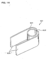
- a fixing member 231 of this modification differs from the above-described fixing member 30 only in first grippers.
- First grippers 232 of this modification are equivalent to the above-described first grippers 35 (see FIG. 4 ) except that openings 233 are formed in centers of them.
- the above-described first grippers 35 are connected with the holder 31 throughout its axial length, whereas the first grippers 232 of this modification have the openings 233 and therefore are connected to the holder 31 at two points, i.e., upper and lower points in the axial direction of the holder 31.
- a connecting portion between the first grippers 232 and the holder 31 has such a degree of strength as to press the first grippers 232 toward each other to thereby expand the slit 33.
- the first grippers 232 can be reduced in weight.
- a fixing member 241 of this modification differs from the above-described fixing member 30 only in first grippers.
- First grippers 242 of this modification are equivalent to the above-described first grippers 35 (see FIG. 4 ) except that protrusions 242 protruding toward each other are provided on opposite faces of the first grippers.
- a fixing member 301 of this modification is equivalent to the above-described fixing member 30 (see FIG. 4 ) except that a pair of second grippers 335 confronting each other are further provided.
- the second grippers 335 protrude in a direction opposite to the protruding direction of the first grippers 35, and they are formed integral with the holder 31 and the first grippers 35.
- boundaries between confronting sides of the respective second grippers 335 and the holder 31 have rounded corners 336.
- the user presses the pair of first grippers 35 toward each other so that the tips thereof can be in contact with each other.
- the diameter -of the through hole 32 becomes slightly larger than the outside diameter of the tube 13, and in this condition the tube 13 is coaxially inserted into the through hole 32.
- the holder 31 is disposed at a predetermined position relative to the tube 13, the pressing against the first grippers 35 is released.
- the user further presses the pair of second grippers 335 toward each other so that tips thereof can be in contact with each other.
- the diameter of the through hole 32 is decreased.
- the fixing member 301 can be fixed to a predetermined position of the tube 13.
- the user grips the second grippers 335 of the fixing member 301 fixed to the tube 13 with the tips of the second grippers 335 being in contact with each other, and in this condition moves the second grippers 335 downward, to insert the pipe 18 of the joint 14 into the tube 13.
- the fixing member 301 can be slid on the outer surface of the tube 13 in the axial direction of the tube 13.
- the fixing member 301 is slid downward.
- the fixing member 301 is fixed in a predetermined position.
- the holder 31 triggers its retaining force that tends to return the diameter of the through hole 32 to its original size, so that the tube 13 is cramped from its outer periphery and held by the holder 31.
- the user presses the second grippers 335 toward each other to increase the holding power of the holder 31. In this condition, the user applies upward pultrusion to the second grippers 335 while gripping the second grippers 335. Thereby, the tube 13 as well as the fixing member 30 can be detached from the pipe 18.
- the holding power applied to the tube 13 by the holder 31 can be improved by pressing the second grippers 335. Accordingly, the tube 13 can surely be fixed by the joint 14.
- the user can insert the tube 13 into the pipe 18 and detach it from the pipe 18 while gripping the second grippers 335. This can prevent deformation of the tube 13 which might occur when these operations are performed by grasping the tube 13 by hand.
- the holding power of the holder 31 produced by pressing the second grippers 335 is kept improved during insertion of the tube 13 into the pipe 18 and detachment of the tube 13 from the pipe 18. Therefore, these operations can be performed efficient manner.
- improved holding power of the holder 31 makes it difficult to cause slipping between the outer surface of the tube 13 and the inner surface of the holder 31, thereby transmitting insertion force or pulling force in an efficient manner. Therefore, even when the pipe 18 cannot easily be fitted into the tube 13 due to, e.g., friction between the inner surface of the tube 13 and the outer surface of the pipe 18, it can appropriately be fitted into the tube 13.
- the second grippers 335 are formed integral with the holder 31 and the first grippers 35, the cramping force applied to the tube 13 by the holder 31 can be adjusted without other members. Therefore, there can be obtained an economical advantage as well.
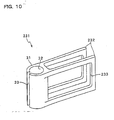
- a fixing member 401 of this modification includes a holder 431 having a through hole 32 and a slit 33, and a pair of protrusions 402 protruding from the holder 431.
- Each protrusion 402 protrudes outward from a portion of an outer surface of the holder 431.
- the portion is a point where the outer surface of the holder 431 intersects the line that passes through the center O of the through hole 32 and extends perpendicularly to the line that connects the center O with the slit 33.
- Each protrusion 402 has a semicylindrical shape, and is formed throughout an entire axial length of the holder 431.
- Each protrusion 402 has an insertion hole 403 formed therethrough in a direction along the line connecting the center O with the slit 33.
- the insertion hole 403 has a substantially rectangular sectional shape.
- the fixing member 401 further includes plate members 404 and 405, and covers 406 and 407.
- the plate members 404 and 405 are slidably inserted into the insertion holes 403 of the respective protrusions 402.
- the covers 406 and 407 are detachably attached to respective ends of the plate members 404 and 405 in their sliding direction.
- the plate members 404 and 405 are made of an elastic material such as spring steels, and slidable into the insertion holes 403.
- the plate members 404 and 405 as inserted into the through holes 403 can be bent around the insertion hole 403 serving as a supporting point.
- Each of the covers 406 and 407 has such a size as to be impassable through the through hole 403, that is, has a section larger than a section of the through hole 403.
- the covers 406 are attached to one ends of the plate members 404 and 405, and in this state the plate members 404 and 405 are inserted into the through holes 403 from the other ends thereof. Then, the other ends of the plate members 404 and 405 are extended from the protrusions 402 in their insertion direction, and the cover 407 are attached to the other ends. Since the covers 406 and 407 cannot pass through the insertion holes 403, the plate members 404 and 405 are not pulled out of the insertion holes 403 and are held in predetermined positions. The provision of the covers 406 and 407 can prevent the plate members 404 and 405 from erroneously being pulled out of the insertion holes 403.
- the plate members 404 and 405 are removed from the holder 431.
- the holder 431 remains and compactification of the fixing member can be realized.
- the slit 33 can be expanded to increase a diameter of the through hole 32.
- the slit 33 can be narrowed to decrease the diameter of the through hole 32. That is, holding power of the holder 431 can be adjusted in substantially the same manner as in the above-described sixth modification.
- a fixing member 501 of this modification is obtained by forming a single elongated plate made of a spring steel into substantially the same shape as that of the above-described fixing member 30.
- a holder 531 By bending the elongated plate into a cylindrical shape, a holder 531 having the same shape as that of the above-described holder 31 is formed.
- a slit 533 similar to the above-described slit 33 is formed at a turned portion of the plate.
- the turned portion turned up at the portion constituting the slit 533 constitutes first grippers 535 that are similar to those of the above-described first grippers 35.
- the first grippers 535 are formed along a peripheral surface of the holder 531 from the portion constituting the slit 533 to portions of the holder 531.
- portions are points where the holder 531 intersects a line that passes through a center of the holder 531 and extends perpendicularly to a line that connects the center with the slit 533. From these portions, the first grippers 535 protrude toward a direction opposite to a direction extending from the center of the holder 531 toward the slit 533.
- the fixing member 501 of this modification is formed of a single plate made of a spring steel, retaining force of the holder 531 can be improved as compared with that of the holder 31. Accordingly, the tube 13 can surely be fixed by the joint 14.
- the pipe 18 in the above-described embodiment has a constant inside diameter.
- the pipe has a constant outside diameter throughout its entire length or the outside diameter of the pipe can be gradually reduced toward one end thereof that is fitted into the tube 13.
- the same effects as described above i.e., the effects that the tube exhibits no excessive deformation and thus airtightness and stability of the tube can be kept well and that repetitive attachment/detachment of the tube does not deteriorate the airtightness and stability of the tube, as long as the following formula is satisfied: ⁇ ⁇ 2 - ⁇ ⁇ 1 / ⁇ ⁇ 2 ⁇ 0.1
- ⁇ 1 represents an outside diameter of the one end of the pipe
- ⁇ 2 represents an outside diameter of the other end of the pipe.
- the pipe 18 may be made of various kinds of metal, and may be made even of a resin, as long as the resin has a low linear expansion coefficient and excellent thermal stability and therefore a shape is hardly deformed.
- the tips of the pair of first grippers 35 and the tips of the pair of second grippers 335 are in contact with each other. It suffices that they are deformable in such a manner that they can be partially in contact with each other.
- the first and second grippers 35 and 335 can be omitted from the fixing member, which may have the holder alone.
- the holder of the fixing member may have various configurations as long as the holder has a slit and a diameter of a through hole can be increased.
Landscapes
- Engineering & Computer Science (AREA)
- General Engineering & Computer Science (AREA)
- Mechanical Engineering (AREA)
- Ink Jet (AREA)
- Clamps And Clips (AREA)
- Quick-Acting Or Multi-Walled Pipe Joints (AREA)
- Supports For Pipes And Cables (AREA)
Claims (16)
- Röhrenbefestigungsstruktur, bei der eine Röhre (13) zum Fördern von Tinte in einem Tintenstrahldrucker an einem Anschlussstück (14) mittels eines Befestigungselements (30) befestigt ist,
wobei das Anschlussstück Folgendes aufweist:ein Rohr (18), dessen erstes Ende in der Röhre angebracht ist, dessen Außendurchmesser größer ist als ein Innendurchmesser der Röhre und dessen Außendurchmesser über seine gesamte Länge konstant ist oder sich zu dessen erstem Ende allmählich verringert, um die folgende Formel zu erfüllen:
wobeiΦ1 einen Außendurchmesser des ersten Endes des Rohres darstellt; undΦ2 einen Außendurchmesser des zweiten Endes des Rohres darstellt; undein Hauptkörper (15) an dem zweiten Ende des Rohres angeschlossen ist,wobei das Befestigungselement einen zylindrischen Halter (31) aufweist, der aus einem flexiblen Material geschaffen ist, das einen Abschnitt der Röhre hält, in der das Rohr angebracht ist, indem der Abschnitt der Röhre um deren Außenumfang geklammert ist, wobei der Halter ein Durchgangsloch (32), durch das die Röhre hindurch angeordnet ist, und einen Schlitz (33) hat, der entlang einer Seite des Durchgangslochs ausgebildet ist. - Röhrenbefestigungsstruktur gemäß Anspruch 1, wobei das Rohr aus Metall besteht.
- Röhrenbefestigungsstruktur gemäß Anspruch 1 oder 2, wobei der Halter so angeordnet ist, dass er das erste Ende des Rohres abdeckt.
- Röhrenbefestigungsstruktur gemäß einem der Ansprüche 1 bis 3, wobei der Schlitz des Befestigungselements entlang einer axialen Richtung der Röhre ausgebildet ist.
- Röhrenbefestigungsstruktur gemäß einem der Ansprüche 1 bis 4, wobei der Schlitz des Befestigungselements über eine gesamte Länge des Durchgangslochs ausgebildet ist.
- Röhrenbefestigungsstruktur gemäß einem der Ansprüche 1 bis 5, wobei das Befestigungselement des Weiteren viele erste Greifer (35) aufweist, die von Abschnitten, wo eine Außenfläche Halters eine Linie schneidet, die durch eine Mitte des Durchgangslochs hindurchtritt und sich senkrecht zu einer Linie erstreckt, die den Schlitz mit der Mitte des Durchgangslochs verbindet, in einer Richtung entgegen einer Richtung vorstehen, die sich von der Mitte des Durchgangslochs zu dem Schlitz erstreckt.
- Röhrenbefestigungsstruktur gemäß einem der Ansprüche 1 bis 5, wobei das Befestigungselement des Weiteren viele erste Greifer (35) aufweist, die von dem Halter in einer Richtung entgegen einer Richtung vorstehen, die sich von der Mitte des Durchgangslochs zu dem Schlitz und senkrecht zu der axialen Richtung des Durchgangslochs erstreckt.
- Röhrenbefestigungsstruktur gemäß Anspruch 6 oder 7, wobei die ersten Greifer des Befestigungselements so ausgebildet sind, dass sie einstückig mit dem Halter sind.
- Röhrenbefestigungsstruktur gemäß Anspruch 6, 7 oder 8, wobei das Befestigungselement des Weiteren viele zweite Greifer (335) aufweist, die von Abschnitten, wo die Außenfläche des Halters die Linie schneidet, die durch die Mitte des Durchgangslochs hindurchtritt und sich senkrecht zu der Linie erstreckt, die den Schlitz mit der Mitte des Durchgangslochs verbindet, in der Richtung vorstehen, die sich von der Mitte des Durchgangslochs zu dem Schlitz erstreckt.
- Röhrenbefestigungsstruktur gemäß einem der Ansprüche 6 bis 8, wobei das Befestigungselement des Weiteren viele zweite Greifer (335) aufweist, die von dem Halter in der Richtung vorstehen, die sich von der Mitte des Durchgangslochs zu dem Schlitz und senkrecht zu der axialen Richtung des Durchgangslochs erstreckt.
- Röhrenbefestigungsstruktur gemäß Anspruch 9 oder 10, wobei die zweiten Greifer des Befestigungselements so ausgebildet sind, dass sie einstückig mit dem Halter und den ersten Greifern sind.
- Röhrenbefestigungsstruktur gemäß einem der Ansprüche 6 bis 11, wobei ein Paar von sich gegenüberliegenden ersten Greifern des Befestigungselements so verformbar ist, dass diese teilweise in Kontakt miteinander sein können.
- Röhrenbefestigungsstruktur gemäß einem der Ansprüche 6 bis 12, wobei Grenzen zwischen dem Halter des Befestigungselements und gegenüberliegenden Seiten eines Paares von sich gegenüberliegenden ersten Greifern des Befestigungselements abgerundete Ecken (336) haben.
- Röhrenbefestigungsstruktur gemäß einem der Ansprüche 1 bis 13, wobei das Befestigungselement des Weiteren Folgendes aufweist:viele Vorsprünge (402), die von derartigen Abschnitten einer Außenfläche des Halters so nach außen vorstehen, dass sie eine Linie schneiden, die durch eine Mitte des Durchgangslochs hindurchtritt und sich senkrecht zu einer Linie erstreckt, die den Schlitz mit der Mitte des Durchgangslochs verbindet, wobei die Vorsprünge einstückig mit dem Halter sind;Einfügungslöcher (403), die durch die jeweiligen Vorsprünge entlang einer Richtung der Linie ausgebildet sind, die den Schlitz mit der Mitte des Durchgangslochs verbindet; undelastische Platten (404, 405), die gleitbar in den Einfügungslöchern eingefügt sind.
- Röhrenbefestigungsstruktur gemäß einem der Ansprüche 1 bis 13, wobei das Befestigungselement des Weiteren Folgendes aufweist:viele Vorsprünge (402), die von dem Halter senkrecht nach außen vorstehen und sich senkrecht zu einer Linie erstrecken, die den Schlitz mit der Mitte des Durchgangslochs verbindet, wobei die Vorsprünge so ausgebildet sind, dass sie einstückig mit dem Halter sind;Einfügungslöcher (403), die durch die jeweiligen Vorsprünge parallel zu einer Linie ausgebildet sind, die den Schlitz mit der Mitte des Durchgangslochs verbindet; undelastische Platten (404, 405), die gleitbar in den Einfügungslöchern eingefügt sind.
- Röhrenbefestigungsstruktur gemäß Anspruch 14 oder 15, wobei das Befestigungselement des Weiteren Abdeckungen (406, 407) aufweist, die lösbar an jeweilige Enden der elastischen Platten hinsichtlich einer Gleitrichtung der Platten angebracht sind, wobei die Abdeckungen jeweils eine derartige Größe haben, dass sie durch das Durchgangsloch nicht hindurchtreten können.
Applications Claiming Priority (2)
| Application Number | Priority Date | Filing Date | Title |
|---|---|---|---|
| JP2003336679 | 2003-09-29 | ||
| JP2003336679A JP4003728B2 (ja) | 2003-09-29 | 2003-09-29 | チューブ固定部材及びチューブ固定構造 |
Publications (3)
| Publication Number | Publication Date |
|---|---|
| EP1519095A2 EP1519095A2 (de) | 2005-03-30 |
| EP1519095A3 EP1519095A3 (de) | 2005-05-25 |
| EP1519095B1 true EP1519095B1 (de) | 2015-04-08 |
Family
ID=34191544
Family Applications (1)
| Application Number | Title | Priority Date | Filing Date |
|---|---|---|---|
| EP04255980.7A Expired - Lifetime EP1519095B1 (de) | 2003-09-29 | 2004-09-29 | Schlauchbefestigungsanordnung und dafür verwendete Befestigungselement |
Country Status (3)
| Country | Link |
|---|---|
| US (1) | US7854450B2 (de) |
| EP (1) | EP1519095B1 (de) |
| JP (1) | JP4003728B2 (de) |
Families Citing this family (12)
| Publication number | Priority date | Publication date | Assignee | Title |
|---|---|---|---|---|
| JP2007232206A (ja) * | 2006-02-01 | 2007-09-13 | Seiko Epson Corp | コネクタ付きチューブとその成形方法 |
| JP2007211826A (ja) * | 2006-02-07 | 2007-08-23 | Yamazaki Kyoiku System Kk | C形ロック部品 |
| EP2237965B1 (de) * | 2008-01-16 | 2012-09-26 | Silverbrook Research Pty. Ltd | Mehrere leitungen aufweisende strömungskupplung mit leckflusssteuerung |
| JP2012000029A (ja) * | 2010-06-15 | 2012-01-05 | Nasunikkusu Kk | 植物用栽培具 |
| JP5861298B2 (ja) * | 2010-09-03 | 2016-02-16 | セイコーエプソン株式会社 | 液体供給装置および液体噴射システム |
| CN103161799B (zh) * | 2013-03-29 | 2015-05-27 | 包小华 | 一种涂料刷滚筒内部结构所用的新型无缝卡簧 |
| EP2979878B1 (de) * | 2013-03-29 | 2020-09-02 | Konica Minolta, Inc. | Bilderzeugungsvorrichtung |
| US10327809B2 (en) * | 2016-02-29 | 2019-06-25 | Covidien Lp | Clip collar advanced fixation |
| GB201618129D0 (en) | 2016-10-26 | 2016-12-07 | Medishield Bv | Device for treatment of anal fistula |
| JP7452021B2 (ja) * | 2020-01-16 | 2024-03-19 | セイコーエプソン株式会社 | 流路部材、及び液体吐出装置 |
| JP7380284B2 (ja) | 2020-02-10 | 2023-11-15 | セイコーエプソン株式会社 | 液体噴射装置 |
| CN120981350A (zh) | 2023-04-27 | 2025-11-18 | 京瓷株式会社 | 液滴喷出头以及记录装置 |
Citations (1)
| Publication number | Priority date | Publication date | Assignee | Title |
|---|---|---|---|---|
| DE19602907A1 (de) * | 1996-01-27 | 1997-07-31 | Bosch Gmbh Robert | Befestigungsanordnung einer Kraftstoffleitung auf einem Stutzen |
Family Cites Families (31)
| Publication number | Priority date | Publication date | Assignee | Title |
|---|---|---|---|---|
| US590094A (en) * | 1897-09-14 | John thomas duncan | ||
| US884256A (en) * | 1907-01-25 | 1908-04-07 | Herbert Guy Addie | Clip. |
| GB101257A (en) | 1916-04-13 | 1916-08-31 | George John Winter | Improvements in Hose Couplings. |
| FR658163A (fr) | 1928-07-27 | 1929-05-31 | Moyen de serrage automatique des colliers de serrage | |
| US2316724A (en) * | 1942-03-09 | 1943-04-13 | Sperry Pierce | Outlet connector with strainer for tanks |
| US3158388A (en) * | 1962-07-13 | 1964-11-24 | Dixon Valve & Coupling Co | Hose coupling connection |
| GB1021309A (en) | 1964-03-19 | 1966-03-02 | Superflexit | Improvements in end fittings for flexible electric conduits |
| US3388227A (en) * | 1967-06-05 | 1968-06-11 | Michael J. Basso | Removable spacer member for installing pushbutton switch assemblies |
| US3572428A (en) * | 1969-01-29 | 1971-03-23 | Motorola Inc | Clamping heat sink |
| US3845521A (en) * | 1972-06-12 | 1974-11-05 | D Mcnichol | Resilient devices for temporarily binding and gripping the edge of materials |
| JPS51161343U (de) | 1975-06-14 | 1976-12-22 | ||
| US4020530A (en) | 1975-12-15 | 1977-05-03 | Sartore James J A | Securable multi-purpose clamp and inserts |
| JPS5576176A (en) | 1978-12-04 | 1980-06-09 | Toho Chem Ind Co Ltd | High temperature dyeing of polyester synthetic fiber |
| JPS5853233B2 (ja) | 1980-07-19 | 1983-11-28 | 株式会社大洋発條製作所 | ホ−ス類のクランプ金具 |
| US4471512A (en) | 1981-09-02 | 1984-09-18 | Trion Industries Inc. | Friction clip for merchandise display hooks and the like |
| JPH0246154B2 (ja) | 1983-12-29 | 1990-10-15 | Matsushita Electric Ind Co Ltd | Denshitaipuraita |
| FR2590919B1 (fr) | 1985-12-03 | 1988-12-30 | Dagonet Daniel | Pince a linge en matiere plastique d'une seule piece |
| EP0302135A1 (de) | 1987-08-07 | 1989-02-08 | Peter Bengsch | Klammer zum Befestigen von flächigen Gegenständen an einem Tragelement |
| JPH02118297A (ja) | 1988-10-28 | 1990-05-02 | Tokai Rubber Ind Ltd | 簡易スイベルホース継手 |
| FR2639088B1 (fr) * | 1988-11-17 | 1990-12-28 | Caoutchouc Manuf Plastique | Accouplement pour tuyau flexible a emboitement par retournement de joint torique sur un cone de faible angle |
| US5141497A (en) * | 1989-06-06 | 1992-08-25 | Becton, Dickinson And Company | Apparatus and method for an introducer |
| JPH0534387A (ja) | 1991-08-02 | 1993-02-09 | Kansai Electric Power Co Inc:The | 電子式電力量計 |
| JPH05270188A (ja) | 1992-03-25 | 1993-10-19 | Tatsuo Nishida | クリップ |
| US5417460A (en) * | 1993-01-15 | 1995-05-23 | Valterra Products, Inc. | Apparatus for mounting a drain hose to an RV waste removal valve assembly |
| US5473796A (en) * | 1994-03-02 | 1995-12-12 | Fusillo; Joseph | Spin-clip bag closure |
| JPH10231977A (ja) | 1998-03-30 | 1998-09-02 | Tokai Rubber Ind Ltd | ホース接続構造 |
| US6003211A (en) * | 1998-06-18 | 1999-12-21 | Chen; Tsung-Jen | Clamp device |
| US6158095A (en) * | 1998-07-02 | 2000-12-12 | Lassiter; Jerry | Power cord clip |
| US6886926B2 (en) | 2001-09-11 | 2005-05-03 | Brother Kogyo Kabushiki Kaisha | Ink-jet printer with ink path and method of forming the ink path |
| JP4934932B2 (ja) | 2001-09-11 | 2012-05-23 | ブラザー工業株式会社 | インクジェット記録装置 |
| US6942532B2 (en) * | 2002-12-19 | 2005-09-13 | Charles Edwin Synder | Clip for surfboard leash |
-
2003
- 2003-09-29 JP JP2003336679A patent/JP4003728B2/ja not_active Expired - Fee Related
-
2004
- 2004-09-24 US US10/948,282 patent/US7854450B2/en not_active Expired - Fee Related
- 2004-09-29 EP EP04255980.7A patent/EP1519095B1/de not_active Expired - Lifetime
Patent Citations (1)
| Publication number | Priority date | Publication date | Assignee | Title |
|---|---|---|---|---|
| DE19602907A1 (de) * | 1996-01-27 | 1997-07-31 | Bosch Gmbh Robert | Befestigungsanordnung einer Kraftstoffleitung auf einem Stutzen |
Also Published As
| Publication number | Publication date |
|---|---|
| JP4003728B2 (ja) | 2007-11-07 |
| US7854450B2 (en) | 2010-12-21 |
| EP1519095A3 (de) | 2005-05-25 |
| JP2005106092A (ja) | 2005-04-21 |
| US20050110272A1 (en) | 2005-05-26 |
| EP1519095A2 (de) | 2005-03-30 |
Similar Documents
| Publication | Publication Date | Title |
|---|---|---|
| EP1519095B1 (de) | Schlauchbefestigungsanordnung und dafür verwendete Befestigungselement | |
| US7229163B2 (en) | Printer | |
| US6755514B2 (en) | Ink jet printer | |
| US8272724B2 (en) | Liquid containers | |
| US8061829B2 (en) | Printing device fluid reservoir with gripping features | |
| US8172386B2 (en) | Sealing device for fluid reservoir | |
| US7988268B2 (en) | Ink tube non-contact image forming apparatus | |
| EP3984756B1 (de) | Tintenpatrone | |
| EP1120257B1 (de) | Druckkopfeinheit | |
| US6948802B2 (en) | Ink jet printer | |
| HK1049645A1 (en) | Ink container for ink jet printer | |
| JP5597076B2 (ja) | 圧力緩衝器、液体噴射ヘッド、液体噴射記録装置、圧力緩衝器用製造治具、および圧力緩衝器の製造方法 | |
| US6648458B2 (en) | Pinch seal providing fluid interconnects between fluid delivery system components | |
| US7201475B2 (en) | Liquid supplying member, method of manufacturing the same, and liquid ejection apparatus incorporating the same | |
| CN1827379B (zh) | 喷墨打印机 | |
| JP2015199338A (ja) | 液体収容体 | |
| JP2008149647A (ja) | 流体供給装置 | |
| CN111376610A (zh) | 打印机以及墨盒 | |
| JP2006256230A (ja) | 液体噴射装置 | |
| EP1719623B1 (de) | Reinigungselement eines Druckkopfes | |
| JP3591561B2 (ja) | インク収納容器 | |
| JP2004137971A (ja) | チューブポンプ用チューブ |
Legal Events
| Date | Code | Title | Description |
|---|---|---|---|
| PUAI | Public reference made under article 153(3) epc to a published international application that has entered the european phase |
Free format text: ORIGINAL CODE: 0009012 |
|
| AK | Designated contracting states |
Kind code of ref document: A2 Designated state(s): AT BE BG CH CY CZ DE DK EE ES FI FR GB GR HU IE IT LI LU MC NL PL PT RO SE SI SK TR |
|
| AX | Request for extension of the european patent |
Extension state: AL HR LT LV MK |
|
| PUAL | Search report despatched |
Free format text: ORIGINAL CODE: 0009013 |
|
| AK | Designated contracting states |
Kind code of ref document: A3 Designated state(s): AT BE BG CH CY CZ DE DK EE ES FI FR GB GR HU IE IT LI LU MC NL PL PT RO SE SI SK TR |
|
| AX | Request for extension of the european patent |
Extension state: AL HR LT LV MK |
|
| 17P | Request for examination filed |
Effective date: 20050613 |
|
| AKX | Designation fees paid |
Designated state(s): DE FR GB |
|
| 17Q | First examination report despatched |
Effective date: 20090827 |
|
| GRAP | Despatch of communication of intention to grant a patent |
Free format text: ORIGINAL CODE: EPIDOSNIGR1 |
|
| INTG | Intention to grant announced |
Effective date: 20141024 |
|
| RIN1 | Information on inventor provided before grant (corrected) |
Inventor name: TAKAGI, OSAMU C/O BROTHER KOGYO KABUSHIKI KAISHA |
|
| GRAS | Grant fee paid |
Free format text: ORIGINAL CODE: EPIDOSNIGR3 |
|
| GRAA | (expected) grant |
Free format text: ORIGINAL CODE: 0009210 |
|
| AK | Designated contracting states |
Kind code of ref document: B1 Designated state(s): DE FR GB |
|
| REG | Reference to a national code |
Ref country code: GB Ref legal event code: FG4D |
|
| REG | Reference to a national code |
Ref country code: DE Ref legal event code: R096 Ref document number: 602004046942 Country of ref document: DE Effective date: 20150521 |
|
| REG | Reference to a national code |
Ref country code: DE Ref legal event code: R097 Ref document number: 602004046942 Country of ref document: DE |
|
| PLBE | No opposition filed within time limit |
Free format text: ORIGINAL CODE: 0009261 |
|
| STAA | Information on the status of an ep patent application or granted ep patent |
Free format text: STATUS: NO OPPOSITION FILED WITHIN TIME LIMIT |
|
| 26N | No opposition filed |
Effective date: 20160111 |
|
| REG | Reference to a national code |
Ref country code: FR Ref legal event code: PLFP Year of fee payment: 13 |
|
| REG | Reference to a national code |
Ref country code: FR Ref legal event code: PLFP Year of fee payment: 14 |
|
| REG | Reference to a national code |
Ref country code: FR Ref legal event code: PLFP Year of fee payment: 15 |
|
| PGFP | Annual fee paid to national office [announced via postgrant information from national office to epo] |
Ref country code: IT Payment date: 20180830 Year of fee payment: 13 |
|
| PGFP | Annual fee paid to national office [announced via postgrant information from national office to epo] |
Ref country code: GB Payment date: 20180828 Year of fee payment: 15 |
|
| GBPC | Gb: european patent ceased through non-payment of renewal fee |
Effective date: 20190929 |
|
| PG25 | Lapsed in a contracting state [announced via postgrant information from national office to epo] |
Ref country code: GB Free format text: LAPSE BECAUSE OF NON-PAYMENT OF DUE FEES Effective date: 20190929 Ref country code: FR Free format text: LAPSE BECAUSE OF NON-PAYMENT OF DUE FEES Effective date: 20190930 |
|
| PGFP | Annual fee paid to national office [announced via postgrant information from national office to epo] |
Ref country code: DE Payment date: 20220615 Year of fee payment: 19 |
|
| REG | Reference to a national code |
Ref country code: DE Ref legal event code: R119 Ref document number: 602004046942 Country of ref document: DE |
|
| PG25 | Lapsed in a contracting state [announced via postgrant information from national office to epo] |
Ref country code: DE Free format text: LAPSE BECAUSE OF NON-PAYMENT OF DUE FEES Effective date: 20240403 |