EP1518994B1 - Führungseinrichtung für die oberen und unteren Teile eines Verschlussorgans und damit versehenes Verschlusssystems - Google Patents
Führungseinrichtung für die oberen und unteren Teile eines Verschlussorgans und damit versehenes Verschlusssystems Download PDFInfo
- Publication number
- EP1518994B1 EP1518994B1 EP04104673A EP04104673A EP1518994B1 EP 1518994 B1 EP1518994 B1 EP 1518994B1 EP 04104673 A EP04104673 A EP 04104673A EP 04104673 A EP04104673 A EP 04104673A EP 1518994 B1 EP1518994 B1 EP 1518994B1
- Authority
- EP
- European Patent Office
- Prior art keywords
- portions
- guiding device
- circular
- radius
- opening
- Prior art date
- Legal status (The legal status is an assumption and is not a legal conclusion. Google has not performed a legal analysis and makes no representation as to the accuracy of the status listed.)
- Expired - Lifetime
Links
Images
Classifications
-
- E—FIXED CONSTRUCTIONS
- E06—DOORS, WINDOWS, SHUTTERS, OR ROLLER BLINDS IN GENERAL; LADDERS
- E06B—FIXED OR MOVABLE CLOSURES FOR OPENINGS IN BUILDINGS, VEHICLES, FENCES OR LIKE ENCLOSURES IN GENERAL, e.g. DOORS, WINDOWS, BLINDS, GATES
- E06B3/00—Window sashes, door leaves, or like elements for closing wall or like openings; Layout of fixed or moving closures, e.g. windows in wall or like openings; Features of rigidly-mounted outer frames relating to the mounting of wing frames
- E06B3/90—Revolving doors; Cages or housings therefor
- E06B3/903—Revolving doors; Cages or housings therefor consisting of arcuate wings revolving around a parallel axis situated outside the wing, e.g. a cylindrical wing revolving around its axis
Definitions
- the present invention relates to a guiding device for guiding in the upper part and / or in the lower part of a closure member of a substantially rectangular opening formed in a partition separating two spaces, the so-called inside, the another said exterior, said member being constituted by at least one wall, having the general shape of a cylinder arc and being rotatable along a vertical axis coinciding with its own axis between an outer sealing position in which said member fits into the opening by closing it completely and being located in said outer space and an inner sealing position in which said member fits into the opening by closing it completely and being located in said interior space.
- It relates more particularly to a guiding device for guiding in the upper part and / or in the lower part of a closure member such as that known from the European patent application No. EP 383,709 .
- an upper annular guide and a lower annular guide are positioned respectively at the upper and lower portion of the amounts of the opening.
- the vertical axis of symmetry of the shutter member passes through the center of the radius of each of the annular guides.
- These guides are intended to facilitate the rotation of the shutter member about its vertical axis when passing from an outer or inner shutter position to an inner or outer shutter position respectively to an intermediate position.
- the object of the invention is to overcome these disadvantages for the upper part and / or the lower part of the closure device by providing a guide system consisting of at least one rigid portion having at least one circular groove and a rail intended to cooperate with said circular groove.
- a guide system consisting of at least one rigid portion having at least one circular groove and a rail intended to cooperate with said circular groove.
- the present invention thus relates to a guiding device for guiding at the top and / or bottom of a shutter member of a substantially rectangular opening in a partition and separating two spaces, one said inside the other said outer, said member being constituted by at least one wall, having the general shape of a cylinder arc and being rotatable along a vertical axis coinciding with its own axis between an outer sealing position in wherein said member fits into the opening by closing it completely and being located in said outer space and an inner sealing position in which said member fits into the opening by closing it completely and being located in said interior space, said top guiding device consisting of a plurality of rigid portions, said portions each having at least one circular main reception means arranged along a radius substantially identical to the radius of said cylinder arc of the member, for receiving a guide rail guiding said member.
- portion in the sense of the present invention is meant an angularly defined portion, “rigid” means a material that is not shapeable or deformable in the human hand without instrument visibly to the eye naked and “circular” means formed in a portion or part of a circle.
- said (or said) portion (s) has (s) furthermore a circular secondary reception means produced according to a radius slightly smaller than the radius of said cylinder arc of the organ, for receiving a secondary guide rail adapted to guide a curtain.
- Said portions preferably have, at their lateral ends, cooperation means for the formation of a completely circular main reception means, in order to facilitate the assembly of the portions forming the high guiding device.
- said portions each have a flat ring shape, each portion having a centripetal radius slightly less than the radius of said cylinder arc of the closure member and a centrifugal radius slightly greater than the radius of said cylinder arc of the shutter member.
- the guide device is preferably composed of p portions, m juxtaposed portions each having at least one circular main reception means and a circular secondary reception means and n juxtaposed portions each having a circular main reception means, to form a completely circular primary reception means, n, m and p being integers.
- n p / 2.
- the main and / or secondary guide rail preferably has a substantially U-shaped cross-section, said U preferably having at least one transverse reinforcement bar positioned parallel to its base and near its opening.
- the main guide rail and the secondary guide rail are identical and they are arranged head to tail respectively in the circular main reception means and in the circular secondary reception means.
- the main and / or secondary reception means is preferably formed on the opening face of said portions, that is to say on the face facing the opening.
- the main and / or secondary reception means preferably has a plurality of holes opening onto the fixed face of said portions, that is to say on the face facing away from the opening, for fixing at least respectively of the main and / or secondary guide rail.
- the portion (s) intended to be arranged in the interior space (s) has a circular groove system on its (or their) face (s) dormant (s), for fixing a semi-cylindrical cover.
- the invention also relates to a closure system of an opening of the type comprising a shutter member movable by rotation along a vertical axis coinciding with its own axis, said member being guided in the upper part and / or in the lower part by a cross member according to the invention.
- Said (or said) portion (s) each having at least one circular main reception means and a circular secondary reception means is (or are) located, preferably, in said outer space.
- Said (or said) wall (s) of said closure member is (or are) constituted (s), preferably at least partially of one (or more) element (s) glazed (s) or plastic.
- the present invention makes it possible to simplify the installation of the shutter members in a cylinder arc such as those known from European Patent Application No. EP 383 70 . It is no longer necessary to manually correct the curvature of the guide rails of the shutter member so that the latter slides properly. In cooperation with the means of reception, the rails take exactly the circular curvature necessary for a good sliding of the shutter member around its axis. Guidance is thus more reliable and less subject to change over time in use, which is important because in the field of building, the manufacturer or installer must a ten-year guarantee on all the operations he performs.
- the guidance system according to the invention is less costly to manufacture than the system of the prior art and in addition, costs less to install because it is no longer necessary to operate recovery of the curvature at the time of the installation.
- the present invention relates to a closure system of an opening (O) of the type comprising a closure member (6) consisting of at least one wall, having the general shape of a cylinder arc, this member being movable by rotation along a vertical axis (ZZ ') coinciding with its own axis.
- the opening (O) is substantially rectangular and is formed in a partition separating two spaces, one said inner (EI), the other said outside (EE).
- said member (6) is rotatable about its vertical axis (ZZ ') between an outer sealing position in which said member (6) fits into the opening (O) by closing it completely and being located in said outer space (EE) and an inner sealing position in which said member (6) fits into the opening (O) by closing it completely and being located in said interior space (EI), as is known from European Patent Application No. EP 383,709 .
- the shutter member may also occupy all the intermediate positions located between these two extremal positions.
- the shutter system according to the invention is provided with a guiding device (G) for guiding the upper part and / or the lower part of the member (6).
- G a guiding device
- Said (or said) wall (s) of said member (6) is (or are) formed at least partially of one (or more) element (s) glazed (s) or plastic.
- the wall of the member (6) consists of a double glazing whose centripetal wall, that is to say the outermost with respect to the axis ZZ ', is a laminated glass.
- this wall can also be made of PMMA.
- the closure member (6) may also consist of two independent walls and can hang together.
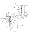
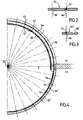
- This guiding device (G) consists of a plurality of portions (52, 52 ') made of a substantially rigid material, said portions (52, 52') each having at least one circular main receiving means (56) produced according to a radius substantially identical to the radius of said cylinder arc of the member (6), for receiving a main guide rail (64) up guiding said member (6) at the top.
- the present invention proposes to position in the upper part a plurality of portions (52, 52 ') which will themselves serve as a guide through their means of reception to the guide rail of the shutter member.
- portions (52, 52 ') are then positioned in the closure system so that the succession of the main reception means (56) of each portion (52, 52') forms a completely and exactly circular guide for the main guide rail (64) is high.
- the wall, or walls where appropriate, constituting the member (6) can be driven (s) in rotation about the axis (ZZ ') precisely because it (s) is / are guided ( s) in its (their) upper part (s) by the guide rail (64) exactly circular.
- portions (52, 52 ') are preferably made of rigid plastic material, such as polypropylene, for example by molding, possibly with a complementary machining operation or only by machining. They can also be made of ABS or wood. Machining with a numerically controlled machine makes it possible to achieve a precision greater than one-tenth of a millimeter, whereas bending of aluminum profiles only achieves an accuracy of the order of several millimeters. It is best to choose a material with a low coefficient of thermal expansion.
- the main guide rail (64) is, as before, made of aluminum alloy, by extrusion.
- the guidance operated by the rail (64) in the upper part is a simple directional guidance, without direct weight of the shutter member.
- the portions (52, 52 ') are intended to be interposed between the ceiling of the closure system and the guide rail (64), in order to conform the rail, in cooperation with the reception means, to its circular shape. ideal.
- the portions (52, 52 ') preferably each have a flat ring shape, each portion having a centripetal radius slightly smaller than the radius of said cylinder arc of the member (6) and a centrifugal radius slightly greater than the radius said cylinder arc of the member (6), to allow saving of the constituent material.
- the guide rail (64) has a substantially U-shaped cross section, said U preferably having at least one transverse reinforcing bar positioned parallel to its base and near its opening. This reinforcing bar can be continuous or positioned equiangularly.
- the width of the U is substantially identical to the width of the main reception means (56).
- the main accommodating means (56) forms a substantially rectangular groove in cross-section.
- the depth of the main reception means (56) is approximately equal to one-third of the thickness of the portions (52, 52 ') and approximately equal to one-tenth of the height of the U-shape, for example of the order of 5 millimeters.
- said main reception means (56) is formed on the underside of said high portions (52, 52 '), but it is possible to imagine that said reception means (56) is made on the centrifugal or even centripetal edge of said portions (52, 52 ').
- the centrifugal radius of curvature of the portions (52) is substantially identical to the centrifugal radius of curvature of the portions (52 '), but the centripetal radius of curvature of the portions (52') is slightly less than the centripetal radius of curvature of the portions (52 '); ), because the portions (52 ') do not comprise secondary receiving means (56'). This saves material for portions (52 '). However, it could also be imagined that only portions (52) are used to achieve the entire high guiding device.
- the guide device thus consists of p portions (52, 52 '), p being equal to n + m.
- the m portions (52) and the n portions (52 ') are juxtaposed so as to form a main means of reception (56) completely circular and a means secondary home (56 ') semicircular.
- each portion (52, 52 ') therefore extends over approximately 90 °.
- closure system has a single portion (52) in said outer space (EE) and a single portion (52 ') in said interior space (EI). Each portion (52, 52 ') then extends over approximately 180 °.
- each portion consisting of a first substantially flat portion located in said outer space (EE) and a substantially flat second portion located in said interior space (EI).
- the reception means (56) has a plurality of holes (57) oriented vertically and opening on the upper or dormant face of said portions (52, 52 '), in order to allow a nut to be slid for both fixing the main guide rail (64) in the receiving means (56) and fixing the portions (52, 52 ') to the rest of the structural work.
- the head of the nut is locked in the opening of the U and the bolt is screwed from above, by inserting a square of fastener (58).
- the head of the nut is locked in the opening of the U and the bolt is screwed from above, by interposing a support vertical fixing (58 ').
- the reception means (56 ') also has a plurality of holes (57') oriented vertically and opening on the upper or dormant face of said portions (52), to allow a nut to be slid for fixing the guide rail secondary (64 ') in the secondary reception means (56').
- portion attachment system (52, 52 ') is completely hidden once the shutter system is fully assembled.
- the holes (57, 57 ') are equiangularly arranged every 11, 25 °.
- an upper plate (20) is disposed between the centripetal walls of the portions (52, 52 ') and a prefabricated half-cylinder (59) is arranged in a circular groove system ( 59 ') formed on the upper or dormant side portions (52') near the centrifugal face.
- the tray (20) can accommodate a lighting device.
- said portions (52, 52 ') have, at their lateral ends, cooperation means making it possible to form a main reception means (56) which is completely circular.
- cooperation means are, for example, the groove / boss type. When these means are made on the edge of the portions (52, 52 '), they participate in the proper centering, so that the main reception means (56) is exactly circular.
- the guide rails (64) and (64 ') are identical. They are then arranged head-to-tail respectively in the circular main reception means (56) and in the circular secondary reception means (56 '), that is to say that the guide rail (64) is arranged in the circular main accommodating means (56) such that the opening of the U is located upwards and the bottom of the groove and the guide rail (64 ') is disposed in the circular secondary receiving means (56 ') so that the opening of the U is located downwards and the base of the U is in the bottom of the groove.
- the side walls of the U-shape of the guide rails (64, 64 ') do not have the same thickness.
- the centripetal wall of the rail (64) may be thinner than the centrifugal wall and the centrifugal wall of the rail (64 ') may be thinner than the centripetal wall.
- the member (6) consists of at least one wall and preferably two substantially identical walls. Each wall is provided at its periphery with a peripheral frame. This frame consists, in its upper part or in its lower part and preferably at the top and bottom, respectively of an upper cross member (62) and a lower cross member for the maintenance of the member (6) of shutter and more precisely for the maintenance of the glazed element (600) which, in the illustrated version, is a bent double glazing.
- said crossmember (62) comprises two circular metal flanges (65, 65 ') between which is positioned at least one rigid circular insert, and preferably two rigid circular inserts, forming a thermal break between said flanges (65, 65'). ).
- inserts (66, 66 ') like the portions (52, 52'), are made of a substantially rigid material, said inserts (66, 66 ') each having a substantially vertical wall formed along a radius substantially identical to the radius of said cylinder arc of the organ (6).
- the flanges (65, 65 ') preferably each have a crown shape, the centrifugal flange (65) having a radius slightly greater than the radius of said cylinder arc of the member (6) and the centripetal flange (65' ) having a radius slightly less than the radius of said cylinder arc of the member (6).
- the present invention proposes to position in the upper part and / or in the lower part - and preferably in the upper and lower part - of the frame at least one (and preferably two) insert (s) (66, 66 ') which goes ( or will be used as a template for the side flanges.
- inserts (66, 66 ') are preferably in one piece for each wall of the closure member, to provide the necessary rigidity template to form a circular guide exactly.
- the wall, or walls where appropriate, constituting the member (6) can be driven (s) in rotation about the ZZ 'axis precisely because they are / are guided (s) in its / their upper part (s) and lower (s) respectively by the guide rails (64, 74) exactly circular and this guidance is not hindered by the side flanges.
- inserts (66, 66 ') are preferably made of rigid plastic material, such as polypropylene, for example by molding, possibly with a complementary machining operation or only by machining. They can also be made of ABS or wood. It is best to choose a material with a low coefficient of thermal expansion.
- Said flanges (65, 65 ') each have respectively on their inward facing side of the cross member at least one appendix (67, 67') intended to cooperate with said insert (66, 66 ').
- each flange (65, 65 ') is not in direct contact with the other flange (65', 65) and the inserts are made of non-heat conducting material.
- said flanges (65, 65') are symmetrical with respect to a vertical axis A of the crossmember.
- This axis A also passes through the center of the guide rail (64), is parallel to the axis ZZ 'and constitutes a reference peripheral ray for expressing the radius of the shutter member.
- each wall of the shutter member is thus constituted in the upper and lower part by the high (62) and low crosspieces.
- This frame is also formed on the lateral edges of each wall of longitudinal sections.
- main guide rail (64) since it has not been specified in the description above that the main guide rail (64) must imperatively constitute a dissociated part rigid portions (52, 52 '), it appears that it it is within the abilities of those skilled in the art to integrate the guide rail into said portions and thus to use a main guide rail (64) which is integral with the portions (52, 52 ') respectively.
Landscapes
- Engineering & Computer Science (AREA)
- Civil Engineering (AREA)
- Structural Engineering (AREA)
- Operating, Guiding And Securing Of Roll- Type Closing Members (AREA)
- Burglar Alarm Systems (AREA)
- Lift-Guide Devices, And Elevator Ropes And Cables (AREA)
- Float Valves (AREA)
- Sampling And Sample Adjustment (AREA)
Claims (14)
- Führungsvorrichtung (G) zum Führen eines Organs (6) für das Verschließen einer im Wesentlichen rechtwinkligen Öffnung (O), die in einer Trennwand angebracht ist und zwei Räume voneinander trennt, wobei der eine Raum als Innenraum (EI) und der andere als Außenraum (EE) bezeichnet wird, im oberen und/oder unteren Teil, wobei das Organ (6) aus mindestens einer Wand mit der allgemeinen Form eines Zylinderbogens gebildet ist und in einer vertikalen Achse (ZZ'), die mit seiner eigenen Achse zusammentrifft, zwischen einer äußeren Verschlussposition, in welcher sich dieses Organ (6) in die Öffnung (O) einbeschreibt, wobei es diese vollständig verschließt und sich in dem Außenraum (EE) befindet, und einer inneren Verschlussposition, in welcher sich dieses Organ (6) in die Öffnung (O) einbeschreibt, wobei es diese vollständig verschließt und sich in dem Innraum (EI) befindet, drehbeweglich ist, dadurch gekennzeichnet, dass sie aus einer Vielzahl starrer Teile (52, 52') für die Aufnahme einer Hauptführungsschiene (64), die das Organ (6) führt, gebildet ist, wobei die Teile (52, 52') jeweils mindestens ein kreisförmiges Hauptaufnahmemittel (56) aufweisen, das mit einem Radius ausgeführt ist, der im Wesentlichen gleich dem Radius des Zylinderbogens des Organs (6) ist.
- Führungsvorrichtung (G) nach Anspruch 1, dadurch gekennzeichnet, dass das/die Teil/e (52) außerdem ein kreisförmiges Nebenaufnahmemittel (56') aufweist/aufweisen, das mit einem Radius ausgeführt ist, der etwas kleiner als der Radius des Zylinderbogens des Organs (6) ist, und das für die Aufnahme einer Nebenführungsschiene (64') vorgesehen ist, die geeignet ist, einen Vorhang zu führen.
- Führungsvorrichtung (G) nach Anspruch 1 oder 2, dadurch gekennzeichnet, dass die Teile (52, 52') an den seitlichen Enden Kooperationsmittel für die Bildung eines vollständig kreisförmigen Hauptaufnahmemittels (56) aufweisen.
- Führungsvorrichtung (G) nach einem der vorhergehenden Ansprüche, dadurch gekennzeichnet, dass die Teile (52, 52') jeweils die Form eines flachen Rings aufweisen, wobei jedes Teil einen zentripetalen Radius, der etwas kleiner als der Radius des Zylinderbogens des Organs (6) ist, und einen zentrifugalen Radius, der etwas größer als der Radius des Zylinderbogens des Organs (6) ist, aufweist.
- Führungsvorrichtung (G) nach einem der vorhergehenden Ansprüche, dadurch gekennzeichnet, dass sie aus p (52, 52') und m nebeneinander liegenden Teilen (52), die jeweils mindestens ein kreisförmiges Hauptaufnahmemittel (56) und ein kreisförmiges Nebenaufnahmemittel (56') aufweisen, und n nebeneinander liegenden Teilen (52'), die jeweils ein kreisförmiges Hauptaufnahmemittel (56) aufweisen, gebildet ist, um ein vollständig kreisförmiges Hauptaufnahmemittel (56) zu bilden, wobei n, m und p ganzzahlig sind.
- Führungsvorrichtung (G) nach Anspruch 5, dadurch gekennzeichnet, dass m = n = p/2.
- Führungsvorrichtung (G) nach einem der Ansprüche 2 bis 6, dadurch gekennzeichnet, dass die Haupt- (64) und/oder Nebenführungsschiene (64') im Querschnitt im Wesentlichen die Form eines U aufweist, wobei das U vorzugsweise mindestens einen quer verlaufenden Verstärkungsstab aufweist, der parallel zu seinem Boden und in der Nähe seiner Öffnung angeordnet ist.
- Führungsvorrichtung (G) nach einem der Ansprüche 2 bis 7, dadurch gekennzeichnet, dass Haupt- (64) und Nebenführungsschiene (64') gleich sind, und dass sie jeweils verkehrt gegeneinander in dem kreisförmigen Hauptaufnahmemittel (56) und dem kreisförmigen Nebenaufnahmemittel (56') angeordnet sind.
- Führungsvorrichtung (G) nach einem der vorhergehenden Ansprüche, dadurch gekennzeichnet, dass das Aufnahmemittel (56, 56') auf der offenen Seite der Teile (52, 52') angebracht ist.
- Führungsvorrichtung (G) nach einem der vorhergehenden Ansprüche, dadurch gekennzeichnet, dass das Aufnahmemittel (56, 56') eine Vielzahl von Löchern (57, 57') aufweist, die auf der ruhenden Seite der Teile (52, 52') münden.
- Führungsvorrichtung (G) nach einem der vorhergehenden Ansprüche, dadurch gekennzeichnet, dass das/die Teil/e (52') auf der/den ruhenden Seite/n ein kreisförmiges Nutensystem aufweist/aufweisen.
- System für das Verschließen einer Öffnung (O) von dem Typ, der ein Verschlussorgan (6) umfasst, das aus mindestens einer Wand gebildet und in einer vertikalen Achse (ZZ') drehbeweglich ist, die mit seiner eigenen Achse zusammenfällt, wobei dieses Organ (6) im oberen und/oder unteren Teil von einer Führungsvorrichtung (G) nach einem der vorhergehenden Ansprüche geführt wird.
- Verschlusssystem nach dem vorhergehenden Anspruch, dadurch gekennzeichnet, dass das/die Teil/e (52) sich in dem Außenraum (EE) befindet/befinden.
- Verschlusssystem nach Anspruch 12 oder 13, dadurch gekennzeichnet, dass die Wand/Wände des Organs (6) wenigstens teilweise aus einem oder mehreren Glas- bzw. Kunststoffelementen gebildet ist/sind.
Applications Claiming Priority (2)
| Application Number | Priority Date | Filing Date | Title |
|---|---|---|---|
| FR0311177A FR2860030B1 (fr) | 2003-09-24 | 2003-09-24 | Dispositif de guidage pour le guidage en partie haute et/ou basse d'un organe d'obturation et systeme d'obturation comportant un tel dispositif de guidage |
| FR0311177 | 2003-09-24 |
Publications (2)
| Publication Number | Publication Date |
|---|---|
| EP1518994A1 EP1518994A1 (de) | 2005-03-30 |
| EP1518994B1 true EP1518994B1 (de) | 2010-03-17 |
Family
ID=34178948
Family Applications (1)
| Application Number | Title | Priority Date | Filing Date |
|---|---|---|---|
| EP04104673A Expired - Lifetime EP1518994B1 (de) | 2003-09-24 | 2004-09-24 | Führungseinrichtung für die oberen und unteren Teile eines Verschlussorgans und damit versehenes Verschlusssystems |
Country Status (4)
| Country | Link |
|---|---|
| EP (1) | EP1518994B1 (de) |
| AT (1) | ATE461351T1 (de) |
| DE (1) | DE602004026016D1 (de) |
| FR (1) | FR2860030B1 (de) |
Citations (1)
| Publication number | Priority date | Publication date | Assignee | Title |
|---|---|---|---|---|
| JPH1181718A (ja) * | 1997-09-12 | 1999-03-26 | Inax Corp | シャワー・トイレユニット |
Family Cites Families (3)
| Publication number | Priority date | Publication date | Assignee | Title |
|---|---|---|---|---|
| FR2584129A1 (fr) * | 1985-07-01 | 1987-01-02 | Kerdoncuff Francois | Sas de securite pour le controle des entrees et sorties dans certains lieux |
| FR2643109B1 (fr) | 1989-02-14 | 1993-10-15 | Salvaire Laurent | Dispositif d'obturation mobile pour une ouverture menagee dans une cloison |
| DE9016617U1 (de) * | 1990-12-07 | 1991-04-18 | B. Kreye Metall- und Biegetechnik GmbH, 4500 Osnabrück | Hebeschiebetür |
-
2003
- 2003-09-24 FR FR0311177A patent/FR2860030B1/fr not_active Expired - Fee Related
-
2004
- 2004-09-24 EP EP04104673A patent/EP1518994B1/de not_active Expired - Lifetime
- 2004-09-24 AT AT04104673T patent/ATE461351T1/de active
- 2004-09-24 DE DE602004026016T patent/DE602004026016D1/de not_active Expired - Lifetime
Patent Citations (1)
| Publication number | Priority date | Publication date | Assignee | Title |
|---|---|---|---|---|
| JPH1181718A (ja) * | 1997-09-12 | 1999-03-26 | Inax Corp | シャワー・トイレユニット |
Also Published As
| Publication number | Publication date |
|---|---|
| FR2860030B1 (fr) | 2005-10-21 |
| ATE461351T1 (de) | 2010-04-15 |
| EP1518994A1 (de) | 2005-03-30 |
| DE602004026016D1 (de) | 2010-04-29 |
| FR2860030A1 (fr) | 2005-03-25 |
Similar Documents
| Publication | Publication Date | Title |
|---|---|---|
| EP2066861B1 (de) | Verbindung von zwei enden von hohlprofilen aus kunststoffmaterial mit hilfe eines verbinders | |
| EP1706554B1 (de) | Aus gespannter leinwand bestehende und durch ein geneigtes trennband verbundene vorgehängte wände | |
| EP1518994B1 (de) | Führungseinrichtung für die oberen und unteren Teile eines Verschlussorgans und damit versehenes Verschlusssystems | |
| FR3009806A1 (fr) | Vitrage a joint profile et enjoliveur, enjoliveur et procede de fabrication du vitrage | |
| EP0223680A2 (de) | Hänger für Unterdecke | |
| EP1518992B1 (de) | Riegelprofil für die Fassung eines Verschlussorgans, und damit versehenes Verschlussorgan sowie Verschlusssystem | |
| EP0112199B1 (de) | Rahmen in Öffnungen bestehend aus Metallprofilen mit unterbrochenen Wärmebrücken und Pressgerät für das Bearbeiten dieser Profile | |
| FR2813624A1 (fr) | Profile de raccord et d'etancheite, dispositif de raccord, panneau a structure sandwich, et ensemble de facade, de cloison ou de couverture | |
| EP2718512B1 (de) | Leuchtende glasstrennwand | |
| FR2952663A1 (fr) | Profiles de maintien mecanique et recouvrement des modules | |
| EP3660257A1 (de) | Verglasungsblock für glastrennwand | |
| EP4284639B1 (de) | Schiebeverbundglasscheibe mit innenliegendem ausgespartem abschnitt und verfahren zur herstellung dieser verbundglasscheibe | |
| FR2514057A1 (fr) | Nouveau panneau vitre, elements pour ce panneau, et procede de pose de ce panneau | |
| EP2597222B1 (de) | Blindwand umfassend gespannte Stoffe, die durch eine Trennleiste miteinander verbunden sind | |
| FR2954683A1 (fr) | Presentoir d'exposition et/ou de rangement | |
| FR3062865A1 (fr) | Procede de montage d'un revetement souple tendu sur un cadre de fixation et cadre de fixation pour la mise en oeuvre dudit procede | |
| FR2800115A1 (fr) | Profile destine a equiper le bord superieur d'une piscine, et piscine ainsi agencee | |
| FR2941725A1 (fr) | Element d'isolation thermique pour bloc prefabrique et bloc de construction ainsi obtenu. | |
| EP1707700B1 (de) | Konstruktionsrahmen einer doppelwandigen demontierbarenTrennwand | |
| EP3115515B1 (de) | Schachtabdeckung mit einem rahmen und einem paneel | |
| EP3751154B1 (de) | Gewindeeinsatz für sandwichpaneel, zusammenbauverfahren und entsprechender zusammenbau | |
| EP2210993B1 (de) | Verkleidungspaneel für Gebäude mit einer Vielzahl von V-förmigen Rippen und entsprechende Konstruktion | |
| BE1006912A3 (fr) | Entretoise pour coffrets pour appareils electriques a disposer cote a cote. | |
| FR2672337A1 (fr) | Procede pour realiser une structure a barreaux et montants, telle qu'une echelle, et structure s'y rapportant. | |
| EP1303671A1 (de) | Vorsatzschale, insbesondere unterdecke bestehend aus einer gespannten leinwand |
Legal Events
| Date | Code | Title | Description |
|---|---|---|---|
| PUAI | Public reference made under article 153(3) epc to a published international application that has entered the european phase |
Free format text: ORIGINAL CODE: 0009012 |
|
| 17P | Request for examination filed |
Effective date: 20040924 |
|
| AK | Designated contracting states |
Kind code of ref document: A1 Designated state(s): AT BE BG CH CY CZ DE DK EE ES FI FR GB GR HU IE IT LI LU MC NL PL PT RO SE SI SK TR |
|
| AX | Request for extension of the european patent |
Extension state: AL HR LT LV MK |
|
| AKX | Designation fees paid |
Designated state(s): AT BE BG CH CY CZ DE DK EE ES FI FR GB GR HU IE IT LI LU MC NL PL PT RO SE SI SK TR |
|
| 17Q | First examination report despatched |
Effective date: 20071219 |
|
| GRAP | Despatch of communication of intention to grant a patent |
Free format text: ORIGINAL CODE: EPIDOSNIGR1 |
|
| GRAS | Grant fee paid |
Free format text: ORIGINAL CODE: EPIDOSNIGR3 |
|
| GRAA | (expected) grant |
Free format text: ORIGINAL CODE: 0009210 |
|
| AK | Designated contracting states |
Kind code of ref document: B1 Designated state(s): AT BE BG CH CY CZ DE DK EE ES FI FR GB GR HU IE IT LI LU MC NL PL PT RO SE SI SK TR |
|
| REG | Reference to a national code |
Ref country code: GB Ref legal event code: FG4D Free format text: NOT ENGLISH |
|
| REG | Reference to a national code |
Ref country code: CH Ref legal event code: EP |
|
| REG | Reference to a national code |
Ref country code: IE Ref legal event code: FG4D |
|
| REF | Corresponds to: |
Ref document number: 602004026016 Country of ref document: DE Date of ref document: 20100429 Kind code of ref document: P |
|
| REG | Reference to a national code |
Ref country code: CH Ref legal event code: NV Representative=s name: KIRKER & CIE S.A. |
|
| REG | Reference to a national code |
Ref country code: NL Ref legal event code: VDEP Effective date: 20100317 |
|
| PG25 | Lapsed in a contracting state [announced via postgrant information from national office to epo] |
Ref country code: PL Free format text: LAPSE BECAUSE OF FAILURE TO SUBMIT A TRANSLATION OF THE DESCRIPTION OR TO PAY THE FEE WITHIN THE PRESCRIBED TIME-LIMIT Effective date: 20100317 Ref country code: FI Free format text: LAPSE BECAUSE OF FAILURE TO SUBMIT A TRANSLATION OF THE DESCRIPTION OR TO PAY THE FEE WITHIN THE PRESCRIBED TIME-LIMIT Effective date: 20100317 Ref country code: SI Free format text: LAPSE BECAUSE OF FAILURE TO SUBMIT A TRANSLATION OF THE DESCRIPTION OR TO PAY THE FEE WITHIN THE PRESCRIBED TIME-LIMIT Effective date: 20100317 |
|
| REG | Reference to a national code |
Ref country code: IE Ref legal event code: FD4D |
|
| PG25 | Lapsed in a contracting state [announced via postgrant information from national office to epo] |
Ref country code: SE Free format text: LAPSE BECAUSE OF FAILURE TO SUBMIT A TRANSLATION OF THE DESCRIPTION OR TO PAY THE FEE WITHIN THE PRESCRIBED TIME-LIMIT Effective date: 20100317 Ref country code: RO Free format text: LAPSE BECAUSE OF FAILURE TO SUBMIT A TRANSLATION OF THE DESCRIPTION OR TO PAY THE FEE WITHIN THE PRESCRIBED TIME-LIMIT Effective date: 20100317 Ref country code: NL Free format text: LAPSE BECAUSE OF FAILURE TO SUBMIT A TRANSLATION OF THE DESCRIPTION OR TO PAY THE FEE WITHIN THE PRESCRIBED TIME-LIMIT Effective date: 20100317 Ref country code: GR Free format text: LAPSE BECAUSE OF FAILURE TO SUBMIT A TRANSLATION OF THE DESCRIPTION OR TO PAY THE FEE WITHIN THE PRESCRIBED TIME-LIMIT Effective date: 20100618 Ref country code: ES Free format text: LAPSE BECAUSE OF FAILURE TO SUBMIT A TRANSLATION OF THE DESCRIPTION OR TO PAY THE FEE WITHIN THE PRESCRIBED TIME-LIMIT Effective date: 20100628 Ref country code: CY Free format text: LAPSE BECAUSE OF FAILURE TO SUBMIT A TRANSLATION OF THE DESCRIPTION OR TO PAY THE FEE WITHIN THE PRESCRIBED TIME-LIMIT Effective date: 20100317 Ref country code: EE Free format text: LAPSE BECAUSE OF FAILURE TO SUBMIT A TRANSLATION OF THE DESCRIPTION OR TO PAY THE FEE WITHIN THE PRESCRIBED TIME-LIMIT Effective date: 20100317 |
|
| PG25 | Lapsed in a contracting state [announced via postgrant information from national office to epo] |
Ref country code: SK Free format text: LAPSE BECAUSE OF FAILURE TO SUBMIT A TRANSLATION OF THE DESCRIPTION OR TO PAY THE FEE WITHIN THE PRESCRIBED TIME-LIMIT Effective date: 20100317 Ref country code: CZ Free format text: LAPSE BECAUSE OF FAILURE TO SUBMIT A TRANSLATION OF THE DESCRIPTION OR TO PAY THE FEE WITHIN THE PRESCRIBED TIME-LIMIT Effective date: 20100317 Ref country code: BG Free format text: LAPSE BECAUSE OF FAILURE TO SUBMIT A TRANSLATION OF THE DESCRIPTION OR TO PAY THE FEE WITHIN THE PRESCRIBED TIME-LIMIT Effective date: 20100617 |
|
| PLBE | No opposition filed within time limit |
Free format text: ORIGINAL CODE: 0009261 |
|
| STAA | Information on the status of an ep patent application or granted ep patent |
Free format text: STATUS: NO OPPOSITION FILED WITHIN TIME LIMIT |
|
| PG25 | Lapsed in a contracting state [announced via postgrant information from national office to epo] |
Ref country code: PT Free format text: LAPSE BECAUSE OF FAILURE TO SUBMIT A TRANSLATION OF THE DESCRIPTION OR TO PAY THE FEE WITHIN THE PRESCRIBED TIME-LIMIT Effective date: 20100719 Ref country code: IE Free format text: LAPSE BECAUSE OF FAILURE TO SUBMIT A TRANSLATION OF THE DESCRIPTION OR TO PAY THE FEE WITHIN THE PRESCRIBED TIME-LIMIT Effective date: 20100317 Ref country code: DK Free format text: LAPSE BECAUSE OF FAILURE TO SUBMIT A TRANSLATION OF THE DESCRIPTION OR TO PAY THE FEE WITHIN THE PRESCRIBED TIME-LIMIT Effective date: 20100317 |
|
| 26N | No opposition filed |
Effective date: 20101220 |
|
| PG25 | Lapsed in a contracting state [announced via postgrant information from national office to epo] |
Ref country code: MC Free format text: LAPSE BECAUSE OF NON-PAYMENT OF DUE FEES Effective date: 20100930 |
|
| PG25 | Lapsed in a contracting state [announced via postgrant information from national office to epo] |
Ref country code: LU Free format text: LAPSE BECAUSE OF NON-PAYMENT OF DUE FEES Effective date: 20100924 Ref country code: HU Free format text: LAPSE BECAUSE OF FAILURE TO SUBMIT A TRANSLATION OF THE DESCRIPTION OR TO PAY THE FEE WITHIN THE PRESCRIBED TIME-LIMIT Effective date: 20100918 |
|
| PG25 | Lapsed in a contracting state [announced via postgrant information from national office to epo] |
Ref country code: TR Free format text: LAPSE BECAUSE OF FAILURE TO SUBMIT A TRANSLATION OF THE DESCRIPTION OR TO PAY THE FEE WITHIN THE PRESCRIBED TIME-LIMIT Effective date: 20100317 |
|
| REG | Reference to a national code |
Ref country code: FR Ref legal event code: PLFP Year of fee payment: 12 |
|
| REG | Reference to a national code |
Ref country code: FR Ref legal event code: PLFP Year of fee payment: 13 |
|
| REG | Reference to a national code |
Ref country code: FR Ref legal event code: TP Owner name: LAURENT SALVAIRE, FR Effective date: 20161122 |
|
| REG | Reference to a national code |
Ref country code: FR Ref legal event code: PLFP Year of fee payment: 14 |
|
| REG | Reference to a national code |
Ref country code: FR Ref legal event code: TP Owner name: LUMICENE, FR Effective date: 20180515 |
|
| REG | Reference to a national code |
Ref country code: FR Ref legal event code: PLFP Year of fee payment: 15 |
|
| PGFP | Annual fee paid to national office [announced via postgrant information from national office to epo] |
Ref country code: PL Payment date: 20180824 Year of fee payment: 6 |
|
| PGFP | Annual fee paid to national office [announced via postgrant information from national office to epo] |
Ref country code: IT Payment date: 20190917 Year of fee payment: 16 Ref country code: DE Payment date: 20190910 Year of fee payment: 16 |
|
| PGFP | Annual fee paid to national office [announced via postgrant information from national office to epo] |
Ref country code: GB Payment date: 20190919 Year of fee payment: 16 Ref country code: AT Payment date: 20190827 Year of fee payment: 16 |
|
| PGFP | Annual fee paid to national office [announced via postgrant information from national office to epo] |
Ref country code: CH Payment date: 20190913 Year of fee payment: 16 |
|
| REG | Reference to a national code |
Ref country code: BE Ref legal event code: MM Effective date: 20190930 |
|
| PG25 | Lapsed in a contracting state [announced via postgrant information from national office to epo] |
Ref country code: BE Free format text: LAPSE BECAUSE OF NON-PAYMENT OF DUE FEES Effective date: 20190930 |
|
| REG | Reference to a national code |
Ref country code: DE Ref legal event code: R119 Ref document number: 602004026016 Country of ref document: DE |
|
| REG | Reference to a national code |
Ref country code: CH Ref legal event code: PL |
|
| REG | Reference to a national code |
Ref country code: AT Ref legal event code: MM01 Ref document number: 461351 Country of ref document: AT Kind code of ref document: T Effective date: 20200924 |
|
| GBPC | Gb: european patent ceased through non-payment of renewal fee |
Effective date: 20200924 |
|
| PG25 | Lapsed in a contracting state [announced via postgrant information from national office to epo] |
Ref country code: DE Free format text: LAPSE BECAUSE OF NON-PAYMENT OF DUE FEES Effective date: 20210401 |
|
| PG25 | Lapsed in a contracting state [announced via postgrant information from national office to epo] |
Ref country code: AT Free format text: LAPSE BECAUSE OF NON-PAYMENT OF DUE FEES Effective date: 20200924 Ref country code: CH Free format text: LAPSE BECAUSE OF NON-PAYMENT OF DUE FEES Effective date: 20200930 Ref country code: GB Free format text: LAPSE BECAUSE OF NON-PAYMENT OF DUE FEES Effective date: 20200924 Ref country code: LI Free format text: LAPSE BECAUSE OF NON-PAYMENT OF DUE FEES Effective date: 20200930 |
|
| PG25 | Lapsed in a contracting state [announced via postgrant information from national office to epo] |
Ref country code: IT Free format text: LAPSE BECAUSE OF NON-PAYMENT OF DUE FEES Effective date: 20200924 |
|
| PGFP | Annual fee paid to national office [announced via postgrant information from national office to epo] |
Ref country code: FR Payment date: 20221202 Year of fee payment: 19 |
|
| PG25 | Lapsed in a contracting state [announced via postgrant information from national office to epo] |
Ref country code: FR Free format text: LAPSE BECAUSE OF NON-PAYMENT OF DUE FEES Effective date: 20230930 |