EP4284639B1 - Schiebeverbundglasscheibe mit innenliegendem ausgespartem abschnitt und verfahren zur herstellung dieser verbundglasscheibe - Google Patents
Schiebeverbundglasscheibe mit innenliegendem ausgespartem abschnitt und verfahren zur herstellung dieser verbundglasscheibe Download PDFInfo
- Publication number
- EP4284639B1 EP4284639B1 EP22706073.8A EP22706073A EP4284639B1 EP 4284639 B1 EP4284639 B1 EP 4284639B1 EP 22706073 A EP22706073 A EP 22706073A EP 4284639 B1 EP4284639 B1 EP 4284639B1
- Authority
- EP
- European Patent Office
- Prior art keywords
- edge
- sheet
- glass sheet
- glass
- glass pane
- Prior art date
- Legal status (The legal status is an assumption and is not a legal conclusion. Google has not performed a legal analysis and makes no representation as to the accuracy of the status listed.)
- Active
Links
Images

Classifications
-
- B—PERFORMING OPERATIONS; TRANSPORTING
- B32—LAYERED PRODUCTS
- B32B—LAYERED PRODUCTS, i.e. PRODUCTS BUILT-UP OF STRATA OF FLAT OR NON-FLAT, e.g. CELLULAR OR HONEYCOMB, FORM
- B32B17/00—Layered products essentially comprising sheet glass, or glass, slag, or like fibres
- B32B17/06—Layered products essentially comprising sheet glass, or glass, slag, or like fibres comprising glass as the main or only constituent of a layer, next to another layer of a specific material
- B32B17/10—Layered products essentially comprising sheet glass, or glass, slag, or like fibres comprising glass as the main or only constituent of a layer, next to another layer of a specific material of synthetic resin
- B32B17/10005—Layered products essentially comprising sheet glass, or glass, slag, or like fibres comprising glass as the main or only constituent of a layer, next to another layer of a specific material of synthetic resin laminated safety glass or glazing
- B32B17/10009—Layered products essentially comprising sheet glass, or glass, slag, or like fibres comprising glass as the main or only constituent of a layer, next to another layer of a specific material of synthetic resin laminated safety glass or glazing characterized by the number, the constitution or treatment of glass sheets
- B32B17/10036—Layered products essentially comprising sheet glass, or glass, slag, or like fibres comprising glass as the main or only constituent of a layer, next to another layer of a specific material of synthetic resin laminated safety glass or glazing characterized by the number, the constitution or treatment of glass sheets comprising two outer glass sheets
-
- B—PERFORMING OPERATIONS; TRANSPORTING
- B32—LAYERED PRODUCTS
- B32B—LAYERED PRODUCTS, i.e. PRODUCTS BUILT-UP OF STRATA OF FLAT OR NON-FLAT, e.g. CELLULAR OR HONEYCOMB, FORM
- B32B1/00—Layered products having a non-planar shape
-
- B—PERFORMING OPERATIONS; TRANSPORTING
- B32—LAYERED PRODUCTS
- B32B—LAYERED PRODUCTS, i.e. PRODUCTS BUILT-UP OF STRATA OF FLAT OR NON-FLAT, e.g. CELLULAR OR HONEYCOMB, FORM
- B32B17/00—Layered products essentially comprising sheet glass, or glass, slag, or like fibres
- B32B17/06—Layered products essentially comprising sheet glass, or glass, slag, or like fibres comprising glass as the main or only constituent of a layer, next to another layer of a specific material
- B32B17/10—Layered products essentially comprising sheet glass, or glass, slag, or like fibres comprising glass as the main or only constituent of a layer, next to another layer of a specific material of synthetic resin
- B32B17/10005—Layered products essentially comprising sheet glass, or glass, slag, or like fibres comprising glass as the main or only constituent of a layer, next to another layer of a specific material of synthetic resin laminated safety glass or glazing
- B32B17/10165—Functional features of the laminated safety glass or glazing
- B32B17/10293—Edge features, e.g. inserts or holes
-
- B—PERFORMING OPERATIONS; TRANSPORTING
- B60—VEHICLES IN GENERAL
- B60J—WINDOWS, WINDSCREENS, NON-FIXED ROOFS, DOORS, OR SIMILAR DEVICES FOR VEHICLES; REMOVABLE EXTERNAL PROTECTIVE COVERINGS SPECIALLY ADAPTED FOR VEHICLES
- B60J1/00—Windows; Windscreens; Accessories therefor
- B60J1/08—Windows; Windscreens; Accessories therefor arranged at vehicle sides
- B60J1/12—Windows; Windscreens; Accessories therefor arranged at vehicle sides adjustable
- B60J1/16—Windows; Windscreens; Accessories therefor arranged at vehicle sides adjustable slidable
- B60J1/17—Windows; Windscreens; Accessories therefor arranged at vehicle sides adjustable slidable vertically
-
- E—FIXED CONSTRUCTIONS
- E05—LOCKS; KEYS; WINDOW OR DOOR FITTINGS; SAFES
- E05F—DEVICES FOR MOVING WINGS INTO OPEN OR CLOSED POSITION; CHECKS FOR WINGS; WING FITTINGS NOT OTHERWISE PROVIDED FOR, CONCERNED WITH THE FUNCTIONING OF THE WING
- E05F11/00—Man-operated mechanisms for operating wings, including those which also operate the fastening
- E05F11/38—Man-operated mechanisms for operating wings, including those which also operate the fastening for sliding windows, e.g. vehicle windows, to be opened or closed by vertical movement
- E05F11/382—Man-operated mechanisms for operating wings, including those which also operate the fastening for sliding windows, e.g. vehicle windows, to be opened or closed by vertical movement for vehicle windows
- E05F11/385—Fixing of window glass to the carrier of the operating mechanism
-
- B—PERFORMING OPERATIONS; TRANSPORTING
- B32—LAYERED PRODUCTS
- B32B—LAYERED PRODUCTS, i.e. PRODUCTS BUILT-UP OF STRATA OF FLAT OR NON-FLAT, e.g. CELLULAR OR HONEYCOMB, FORM
- B32B2307/00—Properties of the layers or laminate
- B32B2307/70—Other properties
- B32B2307/732—Dimensional properties
- B32B2307/737—Dimensions, e.g. volume or area
- B32B2307/7375—Linear, e.g. length, distance or width
- B32B2307/7376—Thickness
-
- E—FIXED CONSTRUCTIONS
- E05—LOCKS; KEYS; WINDOW OR DOOR FITTINGS; SAFES
- E05Y—INDEXING SCHEME ASSOCIATED WITH SUBCLASSES E05D AND E05F, RELATING TO CONSTRUCTION ELEMENTS, ELECTRIC CONTROL, POWER SUPPLY, POWER SIGNAL OR TRANSMISSION, USER INTERFACES, MOUNTING OR COUPLING, DETAILS, ACCESSORIES, AUXILIARY OPERATIONS NOT OTHERWISE PROVIDED FOR, APPLICATION THEREOF
- E05Y2600/00—Mounting or coupling arrangements for elements provided for in this subclass
- E05Y2600/50—Mounting methods; Positioning
- E05Y2600/52—Toolless
- E05Y2600/526—Gluing or cementing
-
- E—FIXED CONSTRUCTIONS
- E05—LOCKS; KEYS; WINDOW OR DOOR FITTINGS; SAFES
- E05Y—INDEXING SCHEME ASSOCIATED WITH SUBCLASSES E05D AND E05F, RELATING TO CONSTRUCTION ELEMENTS, ELECTRIC CONTROL, POWER SUPPLY, POWER SIGNAL OR TRANSMISSION, USER INTERFACES, MOUNTING OR COUPLING, DETAILS, ACCESSORIES, AUXILIARY OPERATIONS NOT OTHERWISE PROVIDED FOR, APPLICATION THEREOF
- E05Y2900/00—Application of doors, windows, wings or fittings thereof
- E05Y2900/50—Application of doors, windows, wings or fittings thereof for vehicles
- E05Y2900/53—Type of wing
- E05Y2900/55—Windows
Definitions
- the present invention relates to a vehicle glazing, and in particular a motor vehicle glazing, comprising a pane and means for allowing the mobility of said pane in vertical translation relative to a door of said vehicle, said pane being curved and laminated and comprising at least one outer glass sheet, one inner glass sheet, and a sheet of adhesive material located between said outer glass sheet and said inner glass sheet, each sheet having a peripheral edge and a thickness.
- a window generally has a line of vision which, when the glazing is considered vertically, creates a separation between, on the one hand, a hidden part of the window which is located below said line of vision and which is intended to be hidden inside said door regardless of the position of said window relative to said door and, on the other hand, a visible part of the window which is located above said line of vision and teaches that it is important that the edges of the three sheets of laminated glass are in lateral continuity with each other in the visible part of the window but that the hidden part may contain an area where only the thick outer sheet of glass is present, the fixing of the glazing being carried out in this area.
- CA3040590A1 discloses a vehicle glazing, comprising a pane and means for allowing the mobility of said pane in vertical translation relative to a door of said vehicle, said pane being curved and laminated and comprising at least one outer glass sheet, one inner glass sheet, and a sheet of adhesive material located between said outer glass sheet and said inner glass sheet, each sheet having a peripheral edge, the edge of said inner glass sheet being located beyond the edge of said plastic sheet and the edge of said outer glass sheet on a portion at least the length of the edge of said inner glass sheet in order to form an external recess, said pane having a line of vision creating, when the glazing is considered vertically, a separation between on the one hand a hidden part of the pane which is located under said line of vision and which is intended to be hidden inside said door whatever the position of said pane relative to said door and on the other hand a visible part of the pane which is located above said line of vision, characterized in that the edge of said inner glass sheet and the edge of said sheet of adhesive material are both in the
- the assembly of the three sheets to form the laminated glass can be particularly complicated when the configuration of the finished laminated glass is complex. Indeed, for complex curvatures, it is difficult to obtain that the thin inner glass sheet follows both perfectly the curve of the thick outer glass sheet over its entire surface and at the same time that the perimeter of the thin inner glass sheet follows perfectly the perimeter of the thick outer glass sheet.
- This local misalignment of the edges can also cause areas of fragility in the laminated glass.
- An aim of the present invention is therefore to propose a movable laminated glazing arrangement which can both be manufactured correctly and quickly and which has an acceptable aesthetic configuration, in particular a periphery having a homogeneous appearance in the visible part of the glass.
- the invention is based on the discovery that rather than locally undergoing a shrinkage or an overflow of the inner glass sheet, it was preferable to design and implement it by lamination in such a way that after lamination, the laminated glass pane deliberately exhibits an internal shrinkage, reduced, visible, but homogeneous in the visible part of the glass pane.
- the invention is further based on providing at least one zone in which this recess is absent, and providing that this zone is in the hidden part of the window, the one which always remains hidden inside the door pillar, whatever the position of the window (open or closed) relative to the door.
- the area in which this withdrawal is absent is a fragile area of the laminated glass but by providing that the withdrawal is absent specifically in a hidden area of the glass, this fragile area is permanently protected inside the door pillar, regardless of the position of the glazing (open or closed) relative to the door.
- the shrinkage is called "internal shrinkage” because it involves making the inner glass sheet smaller than the outer glass sheet; in other words, only the outer glass sheet is entirely at nominal dimensions (dimensions of the bay to be closed).
- the inside recess width is the distance between a plane normal to the edge of the outer glass sheet and a plane normal to the edge of the inner glass sheet.
- the internal shrinkage of the inner glass sheet is applied identically to the sheet of adhesive material located between the two glass sheets.
- Said means for allowing the mobility of said window may comprise, within the meaning of the present invention, one or more holes partially or completely said glass (i.e. over part of the thickness of an element composing it or the entire thickness of this element or over part of the thickness of the glass comprising several elements at this location, or over the entire thickness of the glass), one or more attachment gutters (“holder” in English), one or more rails, or slides.
- Said interior recess preferably further extends into said hidden portion of the glass, to a height of at least 5.0 mm, and preferably to a height of at least 10.0 mm, below said line of sight, in order to ensure that the recess has a homogeneous appearance even slightly beyond the area where it is visible.
- Said internal recess is preferably present along the entirety of a first side edge, a top edge and a second side edge of the glass.
- Said internal recess has a width which is preferably constant along the visible portion of a first lateral edge of the glass and/or along the visible portion of a top edge of the glass and/or along the visible portion of a second lateral edge of the glass, and preferably said internal recess has a constant width along its entire length in said visible portion of the glass.
- Said internal withdrawal is intended to be guided in a guiding and sealing element fixed to said vehicle.
- Said outer glass sheet and said inner glass sheet are preferably such that the thickness of said inner glass sheet is less than the thickness of said outer glass sheet.
- the glass is easier to manufacture because the part(s) of the edge of said inner glass sheet which does not extend beyond the edge of said sheet of adhesive material and the edge of said outer glass sheet may be such that the edge of said inner glass sheet is then in continuity with the edge of the sheet of adhesive material and the edge of the outer glass sheet; this (these) part(s) can then serve as reference area(s) for positioning the inner glass sheet and the adhesive material sheet relative to the curved inner glass sheet during the manufacture of the glass (i.e. during lamination).
- said hidden alignment area is made of a single piece along a bottom edge of said pane.
- the bottom edge of the inner glass sheet can serve as a reference for one (or more) reference stops for positioning the inner glass sheet and the sheet of adhesive material prior to lamination.
- the alignment referencing is particularly reliable.
- a lower edge of said pane comprises three hidden alignment zones and two non-laminated fixing zones, each non-laminated fixing zone being interposed between two successive hidden alignment zones.
- three hidden alignment zones can serve as a reference for reference stops for positioning the inner glass sheet and the sheet of adhesive material prior to lamination.
- the pane can be fixed by means of the fixing zones in which only the outer glass sheet is present; which simplifies the fixing. Furthermore, with three hidden alignment zones, the referencing of the alignment is particularly reliable.
- the glass is laminated glass in the sense that there is no gas space or empty space between the sheets that make up the glass.
- the thickness of said outer glass sheet is between 2.85 mm and 4.85 mm.
- the thickness of said inner glass sheet is between 0.30 mm and 2.60 mm.
- the thickness of said inner glass sheet is between 1.00 mm and 1.20 mm.
- said inner glass sheet has surface stresses of at most 20 MPa, 30 MPa and 40 MPa respectively for a thickness of said inner glass sheet of approximately 1.1 mm, approximately 1.6 mm and approximately 2.1 mm.
- the term "approximately” here designates a value considered by a person skilled in the art as a standard value, even if locally this value can vary within a range of plus or minus 10%.
- edge refers to the narrow side of a leaf, which is located substantially transversely between the two main faces of a leaf.
- the "lateral extension” of an edge is considered according to this transverse direction between the main faces of a leaf.
- the glass is easier to manufacture because the part(s) of the edge of said inner glass sheet and of the edge of said sheet of adhesive material do not extend below the edge of said outer glass sheet can be such that the edge of said inner glass sheet is then in continuity with the edge of said sheet of adhesive material and the edge of said outer glass sheet; this (these) part(s) can then serve as reference part(s) for the positioning of the inner glass sheet and the sheet of adhesive material relative to the outer glass sheet during the manufacture of the glass (i.e. during lamination).
- this (these) part(s) may be located opposite the means allowing the mobility of said window in translation relative to the door of said vehicle (i.e. the window holder(s)) in order to increase the mechanical strength of the window at this location.
- the present invention has been developed for glazing incorporated in doors having side pillars and an upper pillar at the level of the glazing when the latter is raised (closed).
- the present invention makes it possible to produce glazing with a single internal overhang which will be visible to a user of the vehicle, without however being really noticed because it is discreet and preferably constant throughout the visible part of the window.
- FIGS. 1 and 2 illustrate a glazing 1, 1' left side of a vehicle, according to an embodiment of the invention, considered as being seen from the inside of this vehicle.
- This is in particular a side window of a door of a motor vehicle (not visible in Figures 1 and 2 ) which is movable between translation relative to this door substantially along the vertical between an open position in which the glazing is located entirely or almost entirely inside the door and a closed position in which the glazing closes a bay of the door.
- This glazing thus creates, in the closed position, a vertical separation between an interior space I which is inside the vehicle and an exterior space E which is outside the vehicle.
- X axis the central longitudinal axis of advance of the vehicle equipped with the glazing according to the invention as side glazing on the left side of the vehicle and which corresponds to the horizontal axis in the plane of the sheet in Figures 1 and 2 .
- centripetal and that of "centrifugal” is to be considered in the plane of the sheet in figure 1 or 2 , or in a general plane of the glazing when it is considered flat, expressed in relation to the center of the glazing, according to the X and Z axes; the centripetal direction is in the direction of this center of the glazing while the centrifugal direction moves away from this center of the glazing.
- the mobility of the glazing relative to the door is essentially vertical in the sense that this mobility occurs along the Z axis, with possibly a small component along the transverse Y axis not shown in Figures 1 and 2 .
- the glazing 1, 1' is in one piece.
- the glazing 1, 1' comprises a pane 2, 2' which is curved (i.e. not flat) and laminated. However, for simplicity, it is considered in the figures that the pane 2, 2' is flat.
- the pane 2, 2' of the glazing 1, 1' is a laminated pane which comprises, from the outside to the inside, at least, in this order: an outer glass sheet 3, an interlayer sheet of adhesive material 4 then an inner glass sheet 5; however, it is possible that at least one other sheet is interposed between the outer glass sheet 3 and the interlayer sheet of adhesive material 4 or between the interlayer sheet of adhesive material 4 and the inner glass sheet 5.
- the interlayer sheet of adhesive material 4 and the outer glass sheet 3 are seen by transparency through the inner glass sheet 5 in Figures 1 and 2 .
- the glass 2, 2' may consist of the outer glass sheet 3, the interlayer sheet of adhesive material 4 and the inner glass sheet 5, without any other sheet.
- the window 2, 2' has a first side edge 23, a second side edge 24, a top edge 25 and a bottom edge 26.
- the first side edge 23 and the second side edge 24 of the window are arranged respectively in the part of the window facing the front and in the part of the window facing the rear of the vehicle.
- the top edge 25 and the bottom edge 26 of the window are arranged respectively in the part of the window facing the roof and in the part of the window facing the ground on which the vehicle rests.
- the outer glass sheet 3 has an outer face 30 that is oriented toward the outer space E, an intermediate face 32 that is oriented toward the intermediate sheet of adhesive material 4, and a peripheral edge 31 located between these two faces.
- the outer glass sheet 3 has a first lateral edge 33, a second lateral edge 34, a top edge 35 and a bottom edge 36.
- the first lateral edge 33 and the second lateral edge 34 of the outer glass sheet 3 are arranged respectively in the part of the outer glass sheet 3 facing the front and in the part of the outer glass sheet 3 facing the rear of the vehicle.
- the top edge 35 and the bottom edge 36 of the outer glass sheet 3 are arranged respectively in the part of the outer glass sheet 3 facing the roof and in the part of the outer glass sheet 3 facing the chassis of the vehicle.
- the inner glass sheet 5 has an interlayer face 50 that is oriented toward the interlayer sheet of adhesive material 4, an inner face 52 that is oriented toward the interior space I, and a peripheral edge 51 located between these two faces.
- the inner glass sheet 5 has a first lateral edge 53, a second lateral edge 54, a top edge 55, and a bottom edge 56.
- the first lateral edge 53 and the second lateral edge 54 of the inner glass sheet 5 are arranged in the portion of the inner glass sheet 5 facing the front and in the portion of the inner glass sheet 5 facing the rear of the vehicle, respectively.
- the top edge 55 and the bottom edge 56 of the inner glass sheet 5 are arranged in the portion of the inner glass sheet 5 facing the rear of the vehicle, respectively.
- the adhesive material interlayer sheet 4 has an outer interlayer face 40 which is oriented towards the interlayer face 32 and which is here in contact with this interlayer face 32, an inner interlayer face 42 which is oriented towards the interlayer face 50 and which is here in contact with this interlayer face 50, as well as a peripheral edge 41 which is located between these two interlayer faces 40, 42.
- the adhesive material interlayer sheet 4 has a first lateral edge 43, a second lateral edge 44, a top edge 45 and a bottom edge 46.
- the first lateral edge 43 and the second lateral edge 44 of the adhesive material interlayer sheet 4 are arranged respectively in the part of the adhesive material interlayer sheet 4 oriented towards the front and in the part of the adhesive material interlayer sheet 4 oriented towards the rear of the vehicle.
- the upper edge 45 and the lower edge 46 of the adhesive material interlayer sheet 4 are arranged respectively in the part of the adhesive material interlayer sheet 4 facing the roof and in the part of the adhesive material interlayer sheet 4 facing the vehicle chassis.
- the outer glass sheet 3 is a glass sheet that has undergone a thermal bending operation before the manufacture of the laminated glass 2, 2' and having a thickness es of between 2.85 and 4.85 mm, for example 3.50 mm.
- the outer glass sheet 3 may have surface stresses of at least 80 MPa while being less than 200 MPa.
- the inner glass sheet 5 may be a glass sheet that has undergone a thermal tempering operation, or semi-tempering, and having a thickness es of between 0.70 and 2.60 mm, or even between 0.70 and 2.50 mm, or even between 0.70 and 2.30 mm, or even between 0.70 and 2.10 mm, for example 1.10 mm or 1.60 mm.
- the tempering or semi-tempering operations have the advantage of being very quick to perform. Indeed, on average, it is possible to produce approximately 20 glass sheets in one minute. Furthermore, the tempering or semi-tempering operation makes it possible to introduce surface stresses of the order of 20 MPa, 30 MPa and 40 MPa respectively on a glass sheet having a thickness of approximately 1.10 mm, approximately 1.60 mm and approximately 2.10 mm.
- the inner glass sheet 5 may be a glass sheet that has undergone a chemical tempering operation and has a thickness es of between 0.30 and 1.60 mm, or even between 0.50 and 1.50 mm, or even between 0.70 and 1.20 mm, for example 1.10 mm.
- a chemical quenching operation allows surface stresses of at least 200 MPa to be introduced.
- the interlayer sheet of adhesive material 4 is for example a sheet of polyvinyl butyral (PVB) having a thickness e 4 of between 0.30 and 1.50 mm, for example 0.78 mm.
- This sheet of adhesive material 4 preferably has the same dimensions of length along the X axis and of height along the Z axis as the inner glass sheet 5.
- the outer glass sheet 3 is the sheet of the laminated pane which is the outermost.
- the inner glass sheet 5 is not curved before the manufacture of the laminated glass 2, 2'; it is this lamination which will give it its curved shape, following the shape of the outer glass sheet 3. This is made possible by the low thickness of the inner glass sheet 5 relative to that of the outer glass sheet 3.
- the inner glass sheet 5 is curved according to the final shape of the pane 2, 2' before the manufacture of the laminated pane 2.
- the inner glass sheet 5 is curved before the manufacture of the laminated pane 2, 2' into a flatter shape than that which it will ultimately have in the finished laminated pane 2, 2'.
- FIGS. 1 and 2 show that the glass 2, 2' has an outer face 20 which is produced by the outer face 30 of the outer glass sheet 3, an inner face 22 which is produced by the inner face 52 of the inner glass sheet 5 and a peripheral edge 21 located between these two faces, corresponding to the peripheral edge 31 of the outer glass sheet 3, to the peripheral edge 41 of the sheet of adhesive material 4 and to the peripheral edge 51 of the inner glass sheet 5.
- the broken line called "line of vision” or “limit of vision” VL materializes the top of the box of the door inside which the glazing 1, 1' slides.
- This line of vision VL creates, when the glazing is considered vertically, a separation between on the one hand a hidden part of the HP window which is located under the line of vision VL and which is intended to be hidden inside the door whatever the position of the window in relation to said door and on the other hand a visible part of the passenger car window which is located above the passenger car line of vision.
- the glazing 1, 1' has one and preferably here two fixing zones F, F' in each of which a glass holder 6 is fixed to the glass 2, 2' (only the glass holders of the glass of the figure 1 are illustrated).
- Glazing 1, 1' of Figures 1 and 2 thus comprises, in addition to the window 2, 2', along at least a portion of at least one bottom edge 26, at least one window holder which is intended to accommodate an attachment element, not shown, which is intended to allow the window holder to be attached in a movement system for raising and lowering the glazing.
- Some documents refer to this as a "regulator" system.
- the glazing 1, 1' in its configuration of use, thus preferably comprises two glass holders.
- the means for allowing the mobility of the window 2 in translation relative to a door of the vehicle comprise at least one and preferably at least two window holders 6, 6' having for example in cross section substantially an inverted H shape.
- the edge 51 of the inner glass sheet and the edge 41 of said sheet of adhesive material are both in the lateral extension of the edge 31 of said outer glass sheet.
- the assembly is carried out in such a way that said parallel walls 63, 64 of said h-shape encase the window 2 in its lower part, the tail 65 then being substantially in the extension of the window 2.
- This h-shape of the window holder is particularly advantageous because it allows the transmission of forces between the window holder and the window over a large surface area corresponding to the sum of the interior surfaces of the parallel walls 63, 64; however, It is quite possible to use a simple plate, this plate having for example at least two parts: a first part for cooperation with the window and a second part for cooperation with the drive mechanism (raising/lowering) of the window.
- the window 2 is illustrated flat and the parallel walls 63, 64 and the tail 65 are flat but the window 2 is curved and the parallel walls 63, 64 and/or the tail 65 may be curved.
- the tail 65 extends approximately from half of the base connecting the parallel walls 63, 64, but it is also possible to position the tail 65 in the extension of one or the other of the parallel walls 63, 64.
- the tail 65 is not parallel to the walls 63, 64.
- the axis A illustrating the mean plane of the glazing 1 at its lower end when the latter is correctly positioned with respect to the window holder 6, the tail 65 is oriented at a non-zero angle with respect to the axis T and which is a function of the curvature of the window 2.
- the tail 65 is intended to be connected to a motorized drive system not illustrated to allow the raising and lowering of the glazing 1 in the door of the vehicle.
- the assembly of the 6, 6' glass holders to the laminated 2 glass is carried out on a template allowing the tolerances to be checked on the 6, 6' glass holder / 2 glass assembly.
- the glass 2 Before positioning and securing the glass holders, the glass 2 is first correctly positioned (“focused”) in a mounting jig having a plurality of positioning stops.
- One of the positioning stops is designated as point Y3 and is preferably positioned on the VL line of sight illustrating the position of a low contact seal with the door when the glazing is closed.
- the window holder(s) 6, 6' is (or are) glued using a glue, for example polyurethane, then "fitted" on the window 2, that is to say that it (they) is (or are) positioned so that the window is present in the U shape, in abutment or not, by inserting between said parallel walls 63, 64 and the window 2 a plastic insertion material 66, such as for example polypropylene.
- a glue for example polyurethane
- an in-situ injection of adhesive material intended to form the insertion material 66 is proposed, which is made of thermoplastic hot-melt resin, for example based on polyamide.
- the positioning of the insert material 66 when the glass and the glass holders are correctly positioned relative to each other thus guarantees the position of the glass holder, whatever the curve of the glass.
- the hot melt resin used has a yield strength of approximately 5.5 N/ mm2 and a breaking strength of 11 N/ mm2 , calculated according to DIN 53455. It must be used at a temperature of approximately 220 °C and has a viscosity at this temperature of around 5000 mPa.s, measured according to ASTM D 3236.
- the glass holders used are preferably made of aluminium alloy.
- aluminium alloy of grade 6060 AGS
- a vertical pressing force of 30 to 50 tonnes is sufficient, i.e. relative to the size of the glass holders, forces of approximately 150 GPa for h-shaped glass holders with an overall dimension of approximately 40x30 mm and of approximately 450 GPa for h-shaped glass holders with an overall dimension of approximately 60x60 mm.
- the glass 2' is not laminated: the three elements constituting at least the lamination are not all present over the entire surface of the fixing zone F, F', as detailed below.
- the two fixing zones F, F' of the glazing 1' of the figure 2 has a hole or that the two fixing zones F, F' of the glazing 1' do not have any holes.
- the lower edge 56 of the inner glass sheet 5, as well as the lower edge 46 of the adhesive sheet of adhesive material 4 are much higher than the lower edge 36 of the outer glass sheet 3.
- the lower edge 56 of the inner glass sheet 5 and the lower edge 46 are located approximately halfway, according to the vertical between the line of vision VL and the lower edge 36 of the outer glass sheet 3.
- the outer sheet 3 has a hole 33, tubular, opening onto the two faces of the outer sheet 3, the outer face 30 and the inner face 32.
- This hole 33 has an axis and has a circular internal section; it does not open onto the edge 31 of the outer sheet 3: it is completely circular in section and it is not a notch.
- the edge 51 of the inner glass sheet 5 and the edge 41 of the sheet of adhesive material 4 are located below the edge 31 of said outer glass sheet 3 in order to form an internal recess 9 having a width W extending in the centripetal direction, and this internal recess is particular because it is not completely peripheral; it does not extend along the entire periphery of the window: in at least one hidden alignment zone HAZ1, HAZ2, HAZ3, there is no internal recess and the edge 51 of said inner glass sheet 5 and the edge 41 of said sheet of adhesive material 4 are both in the lateral extension of the edge 31 of the outer glass sheet 3; this hidden alignment zone is located in the hidden part of the HP glass so that it remains permanently hidden inside the door box, whatever the position of the glazing relative to this door (glazing open or closed or in an intermediate position between the two).
- This internal recess 9 is unique in the visible part of the VP window and has a relatively narrow width W of between 0.8 mm and 5.0 mm, and preferably of between 1.0 mm and 4.0 mm, or even of between 1.2 mm and 3.8 mm, and is present in the entirety of said visible part of the VP window.
- This internal recess 9 may not extend to the bottom of the first lateral edge 23 and/or the second lateral edge 24 but it extends in the visible part of the window, at least up to the line of vision VL and preferably extends, from this line of vision VL, in the hidden part of the HP window, over a height of at least 5.0 mm, and preferably over a height of at least 10.0 mm, downwards, under the line of vision VL. It is therefore possible to produce a hidden alignment zone in the bottom of the first lateral edge 23 and/or in the bottom of the second lateral edge 24, in particular to allow referencing to be carried out along the X axis alone.
- said internal recess 9 is present along the entire first lateral edge 23, the entire top edge 25 and the entire second lateral edge 24 of the window.
- the hidden alignment zone(s) are therefore located along the bottom edge 26 of the window 2 or at the corner between on the one hand the first lateral edge 23 and the bottom edge 26 and/or on the other hand the second lateral edge 24 and the bottom edge 26.
- the three hidden alignment zones HAZ1, HAZ2, HAZ3 in figure 2 each allow a positioning mark to be made for the adhesive material sheet 4 and the inner glass sheet 5 relative to the outer glass sheet 3 along at least the Z axis, before lamination.
- the inner recess 9 has a width W which may be constant along the visible portion of the first lateral edge 23 of the pane and/or along the visible portion of the top edge 25 of the pane and/or along the visible portion of the second lateral edge 24 of the pane; however, it is preferable that the inner recess 9 has a constant width W along its entire length in said visible portion of the pane VP. It is not necessary for it to have the same width W in the hidden portion of the pane HP if it is present in this hidden portion of the pane HP.
- At least one stop is located in a hidden alignment area.
- the entire portion of the glazing that is located below the VL vision limit may not have an internal recess: in this portion below the VL vision limit, inside the door box when the glazing is closed, it is possible that the edge 31 of the outer glass sheet 3 over one (or more) part(s) of its length, or even over its entire length, is in continuity with the edge 51 of the inner glass sheet 5, or it is possible that the edge 31 of the outer glass sheet 3 over one (or more) part(s) of its length, or even over its entire length, extends further, in a centrifugal direction, than the edge 51 of the inner glass sheet 5.
- edge 51 of the inner glass sheet 5 is in continuity with the edge 31 of the outer glass sheet 3 only where there are means for allowing the mobility of the window 2 in translation relative to a door of the vehicle.
- each of the edges 53, 54, and 55 of said inner glass sheet 5 is thus located below, in a centripetal direction, the edge 31 of said outer glass sheet 3 (and the edge 41 of the sheet of adhesive material 4) forming a single inner recess 9, or centripetal offset.
- Each sheet 3, 4, 5 has a peripheral perimeter P 3 , P 4 , P 5 : the perimeter P 5 of the inner glass sheet 5 and the perimeter P 4 of the sheet of adhesive material 4 extend below the perimeter P 3 of the outer glass sheet 3 in the entire visible part VP of the window.
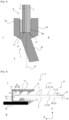
- FIG. 4 illustrates the guiding of the edge of the glazing 1, 1' in a guiding and sealing element 71 fixed to said vehicle.
- the figure 4 illustrates a partial sectional view of the first edge 23 of the window 2, 2' and shows one of the vertical guide elements of the glazing 1, 1' which is fixed to the front of the door.
- the guide element comprises, in particular, a first guide and sealing element 71 for guiding the window 2, 2' in translation along the Z axis and a first covering piece 70 having the function of hiding the guide and sealing element 71.
- the first side edge 23 is in contact and slides between a spherical protuberance 72 and a seal comprising two lips 73, 73'.
- the seal 73 may comprise one lip or more than two lips.
- Another guide element (not visible) of the glazing 1, 1' is fixed to the rear of the door, making it possible to guide the second lateral edge 24 of the window 2, 2' in translation along the Z axis.
- the inner glass sheet 5 is in contact with all the inner sealing elements of the guide and sealing element 71.
- the inner recess 9 therefore has a substantial width, without this width requiring the provision of specific inner sealing.
Landscapes
- Engineering & Computer Science (AREA)
- Mechanical Engineering (AREA)
- Joining Of Glass To Other Materials (AREA)
- Laminated Bodies (AREA)
- Securing Of Glass Panes Or The Like (AREA)
Claims (10)
- Fahrzeugverglasung (1, 1'), vorweisend ein Fenster (2, 2') sowie Mittel zum Ermöglichen der Beweglichkeit des Fensters (2, 2') in vertikaler Translation relativ zu einer Tür des Fahrzeugs, wobei das Fenster (2, 2') gewölbt und laminiert ist und mindestens eine äußere Glasscheibe (3), eine innere Glasscheibe (5) sowie eine Scheibe aus Haftmaterial (4) umfasst, die sich zwischen der äußeren Glasscheibe (3) und der inneren Glasscheibe (5) befindet, wobei jede Scheibe eine Umfangskante aufweist, wobei die Kante (51) der inneren Glasscheibe (5) und die Kante (41) der Haftmaterialschicht (4) unterhalb der Kante (31) der äußeren Glasscheibe (3) gelegen sind, um eine innere Aussparung (9) auszubilden, die eine Breite (W) aufweist, wobei das Fenster (2, 2'), wenn die Verglasung vertikal betrachtet wird, eine Sichtlinie (VL) aufweist, die eine Trennung zwischen einerseits einem verborgenen Teil des Fensters (HP), der unter der Sichtlinie (VL) gelegen ist und der dafür bestimmt ist, innerhalb der Tür verborgen zu werden, unabhängig von der Position des Fensters relativ zu der Tür, und andererseits einem sichtbaren Teil des Fensters (VP) umzusetzen, der oberhalb der Sichtlinie (VL) gelegen ist, dadurch gekennzeichnet, dass:- die Kante (51) der inneren Glasscheibe (5) und die Kante (41) der Haftmaterialschicht (4) beide in der seitlichen Verlängerung der Kante (31) der äußeren Glasscheibe (3) in mindestens einer verborgenen Ausrichtungszone (HAZ1) oder sogar in mehreren verborgenen Ausrichtungszonen (HAZ2, HAZ3) sind, die jeweils in dem verborgenen Teil des Fensters (HP) gelegen ist/sind, und- die innere Aussparung (9) eine Breite (W) zwischen 0,8 mm und 5,0 mm und vorzugsweise zwischen 1,0 mm und 4,0 mm oder sogar zwischen 1,2 mm und 3,8 mm aufweist und in dem gesamten sichtbaren Teil des Fensters (VP) vorhanden ist.
- Verglasung (1, 1') nach Anspruch 1, wobei die innere Aussparung (9) sich in dem verdeckten Teil des Fensters (HP) über eine Höhe von mindestens 5,0 mm und vorzugsweise über eine Höhe von mindestens 10,0 mm unter der Sichtlinie (VL) erstreckt.
- Verglasung (1, 1') nach Anspruch 1 oder 2, wobei die innere Aussparung (9) entlang der gesamten ersten Seitenkante (23), einer Oberkante (25) und einer zweiten Seitenkante (24) des Fensters (2, 2') vorhanden ist.
- Verglasung (1, 1') nach einem der Ansprüche 1 bis 3, wobei die innere Aussparung (9) entlang des sichtbaren Teils einer ersten Seitenkante (23) des Fensters (2, 2') und/oder entlang des sichtbaren Teils einer Oberkante (25) des Fensters (2, 2') und/oder entlang des sichtbaren Teils einer zweiten Seitenkante (24) des Fensters (2, 2') eine konstante Breite (W) aufweist und vorzugsweise die innere Aussparung (9) eine entlang ihrer gesamten Länge in dem sichtbaren Teil des Fensters (VP) eine konstante Breite (W) aufweist.
- Verglasung (1, 1') nach einem der Ansprüche 1 bis 4, wobei die innere Glasscheibe (5) Oberflächenspannungen von maximal 20 MPa, 30 MPa beziehungsweise 40 MPa für eine Dicke der äußeren Glasscheibe (3) von etwa 1,1 mm, etwa 1,6 mm und etwa 2,1 mm aufweist.
- Verglasung (1, 1') nach einem der Ansprüche 1 bis 4, wobei die innere Glasscheibe (5) minimale Oberflächenspannungen von 200 MPa aufweist.
- Verglasung (1) nach einem der Ansprüche 1 bis 6, wobei die verborgene Ausrichtungszone (HAZ1) entlang einer Unterkante (26) des Fensters (2) einstückig gebildet ist.
- Verglasung (1') nach einem der Ansprüche 1 bis 6, wobei eine Unterkante (26) des Fensters (2') drei verdeckte Ausrichtungszonen (HAZ1, HAZ2, HAZ3) und zwei nicht laminierte Befestigungszonen (F, F) vorweist, wobei jede nicht laminierte Befestigungszone (F, F') zwischen zwei aufeinanderfolgenden verborgenen Ausrichtungszonen eingeschoben ist.
- Verglasung (1, 1') nach einem der Ansprüche 1 bis 8, wobei die innere Aussparung (9) dafür bestimmt ist, in einem an dem Fahrzeug befestigten Führungs- und Dichtungselement (71) geführt zu werden.
- Verfahren zum Herstellen einer Fahrzeugverglasung (1, 1') nach einem der Ansprüche 1 bis 9, wobei die Verglasung (1, 1') ein Fenster (2, 2') sowie Mittel zum Ermöglichen der Beweglichkeit des Fensters (2, 2') in vertikaler Translation relativ zu einer Tür des Fahrzeugs vorweist, wobei das Fenster (2) , 2') gewölbt und laminiert ist und mindestens eine äußere Glasscheibe (3), eine innere Glasscheibe (5) sowie eine Scheibe aus Haftmaterial (4) umfasst, die sich zwischen der äußeren Glasscheibe (3) und der inneren Glasscheibe (5) befindet, wobei jede Scheibe eine Umfangskante aufweist, wobei die Kante (51) der inneren Glasscheibe (5) und die Kante (41) der Haftmaterialschicht (4) unterhalb der Kante (31) der äußeren Glasscheibe (3) gelegen sind, um eine innere Aussparung (9) auszubilden, die eine Breite (W) aufweist, wobei das Fenster (2, 2'), wenn die Verglasung vertikal betrachtet wird, eine Sichtlinie (VL) aufweist, die eine Trennung zwischen einerseits einem verborgenen Teil des Fensters (HP), der unter der Sichtlinie (VL) gelegen ist und der dafür bestimmt ist, innerhalb der Tür verborgen zu werden, unabhängig von der Position des Fensters relativ zu der Tür, und andererseits einem sichtbaren Teil des Fensters (VP) umzusetzen, der oberhalb der Sichtlinie (VL) gelegen ist, dadurch gekennzeichnet, dass:- für den Vorgang des Herstellens des Fensters (2, 2') durch Laminieren, die Kante (51) der inneren Glasscheibe (5) und die Kante (41) der Haftmaterialschicht (4) beide in der seitlichen Verlängerung der Kante (31) der äußeren Glasscheibe (3) in mindestens einer verborgenen Ausrichtungszone (HAZ1) oder sogar in mehreren verborgenen Ausrichtungszonen (HAZ2, HAZ3) positioniert sind, die jeweils in dem verborgenen Teil des Fensters (HP) gelegen ist/sind, und so positioniert sind, dass- nach dem Laminieren, die innere Aussparung (9) eine Breite (W) zwischen 0,8 mm und 5,0 mm und vorzugsweise zwischen 1,0 mm und 4,0 mm oder sogar zwischen 1,2 mm und 3,8 mm aufweist und in dem gesamten sichtbaren Teil des Fensters (VP) vorhanden ist.
Applications Claiming Priority (2)
| Application Number | Priority Date | Filing Date | Title |
|---|---|---|---|
| FR2100742A FR3119112B1 (fr) | 2021-01-27 | 2021-01-27 | vitrage FEUILLETE COULISSANT A RETRAIT INTERIEUR ET PROCEDE DE FABRICATION DE CE VITRAGE |
| PCT/FR2022/050140 WO2022162309A1 (fr) | 2021-01-27 | 2022-01-26 | Vitrage feuillete coulissant a retrait interieur et procede de fabrication de ce vitrage |
Publications (2)
| Publication Number | Publication Date |
|---|---|
| EP4284639A1 EP4284639A1 (de) | 2023-12-06 |
| EP4284639B1 true EP4284639B1 (de) | 2024-11-13 |
Family
ID=75690397
Family Applications (1)
| Application Number | Title | Priority Date | Filing Date |
|---|---|---|---|
| EP22706073.8A Active EP4284639B1 (de) | 2021-01-27 | 2022-01-26 | Schiebeverbundglasscheibe mit innenliegendem ausgespartem abschnitt und verfahren zur herstellung dieser verbundglasscheibe |
Country Status (6)
| Country | Link |
|---|---|
| US (1) | US20240092063A1 (de) |
| EP (1) | EP4284639B1 (de) |
| CN (1) | CN115916562B (de) |
| FR (1) | FR3119112B1 (de) |
| PL (1) | PL4284639T3 (de) |
| WO (1) | WO2022162309A1 (de) |
Family Cites Families (11)
| Publication number | Priority date | Publication date | Assignee | Title |
|---|---|---|---|---|
| SE357525B (de) * | 1968-01-29 | 1973-07-02 | Saint Gobain | |
| DE8910916U1 (de) * | 1989-09-13 | 1989-10-26 | VEGLA Vereinigte Glaswerke GmbH, 5100 Aachen | Autoglasscheibe, insbesondere höhenverstellbare Seitenscheibe |
| DE10237756A1 (de) * | 2002-08-17 | 2004-03-04 | Saint-Gobain Sekurit Deutschland Gmbh & Co. Kg | Verfahren zum Herstellen eines höhenverstellbaren Fahrzeugfensters und höhenverstellbares Fahrzeugfenster |
| BE1020051A3 (fr) | 2011-07-04 | 2013-04-02 | Agc Glass Europe | Vitrage automobile. |
| FR2981295B1 (fr) * | 2011-10-14 | 2020-02-21 | Saint-Gobain Glass France | Fabrication d'un vitrage feuillete |
| BE1020862A3 (fr) | 2012-08-21 | 2014-06-03 | Agc Glass Europe | Vitrage automobile. |
| JP6720741B2 (ja) * | 2015-08-07 | 2020-07-08 | Agc株式会社 | 積層板および中間膜 |
| CN108367981B (zh) | 2015-12-21 | 2021-01-15 | Agc株式会社 | 层叠板 |
| FR3058096B1 (fr) * | 2016-10-28 | 2018-12-07 | Saint-Gobain Glass France | Vitrage feuillete coulissant a debord interieur |
| FR3058097B1 (fr) * | 2016-10-28 | 2018-12-07 | Saint-Gobain Glass France | Vitrage feuillete coulissant a debord interieur |
| JP7471278B2 (ja) * | 2018-08-31 | 2024-04-19 | ピルキントン グループ リミテッド | 積層ガラス |
-
2021
- 2021-01-27 FR FR2100742A patent/FR3119112B1/fr active Active
-
2022
- 2022-01-26 EP EP22706073.8A patent/EP4284639B1/de active Active
- 2022-01-26 WO PCT/FR2022/050140 patent/WO2022162309A1/fr not_active Ceased
- 2022-01-26 PL PL22706073.8T patent/PL4284639T3/pl unknown
- 2022-01-26 US US18/263,086 patent/US20240092063A1/en active Pending
- 2022-01-26 CN CN202280001776.8A patent/CN115916562B/zh active Active
Also Published As
| Publication number | Publication date |
|---|---|
| EP4284639A1 (de) | 2023-12-06 |
| PL4284639T3 (pl) | 2025-02-24 |
| WO2022162309A1 (fr) | 2022-08-04 |
| US20240092063A1 (en) | 2024-03-21 |
| FR3119112B1 (fr) | 2023-01-20 |
| FR3119112A1 (fr) | 2022-07-29 |
| CN115916562B (zh) | 2025-06-20 |
| CN115916562A (zh) | 2023-04-04 |
Similar Documents
| Publication | Publication Date | Title |
|---|---|---|
| EP3532288B1 (de) | Schiebeverbundglasscheibe mit internem überhang | |
| EP3532287B1 (de) | Schiebeverbundglasscheibe mit innenseitigem überhang | |
| CA2590679C (fr) | Vitrage complexe constitue d'au moins deux elements vitres contigus et procede de realisation de ce vitrage complexe. | |
| EP3347218B1 (de) | Seitliche verglasung eines verkehrsmittels zur befestigung von aussen | |
| EP3600934B1 (de) | Verglasung mit einer einzelprofilierten wulst zur verbindung zweier fenster sowie fenster für solch eine verglasung | |
| WO2008104715A2 (fr) | Procede d'assemblage par collage d'un vitrage sur son support et moyens pour la mise en oeuvre de ce procede | |
| EP4401996B1 (de) | System zur befestigung einer seitenverglasung eines transportmittels mit einem schloss mit mindestens einer verwechslungssicherungsprojektion | |
| EP4284639B1 (de) | Schiebeverbundglasscheibe mit innenliegendem ausgespartem abschnitt und verfahren zur herstellung dieser verbundglasscheibe | |
| EP4126527B1 (de) | Verbundglasscheibe für ein kraftfahrzeug, insbesondere eine seitenverglasung | |
| EP4334559B1 (de) | Verfahren zur herstellung einer gleitverglasungseinheit und gleitverglasungseinheit | |
| EP4007695B1 (de) | Schiebeverbundglasscheibe mit internem seitenüberhang | |
| FR2990650A1 (fr) | Pare-brise hybride allege pour vehicule formant une bulle panoramique. | |
| EP4472868B1 (de) | Elektrische verbindung für eine schiebeverglasungseinheit eines fahrzeugs, verglasungseinheit und fahrzeug mit dieser elektrischen verbindung | |
| WO2022234216A1 (fr) | Procede de fabrication d'un vitrage coulissant et vitrage coulissant | |
| EP4185480B1 (de) | Verglasung mit einem fensterhalter in schmaler bauweise und verfahren zur herstellung der verglasung | |
| FR2990649A1 (fr) | Pare-brise hybride pour vehicule comprenant un premier panneau en verre feuillete epaule contre un second panneau en polycarbonate. | |
| FR3106775A1 (fr) | Vitrage feuillete coulissant a debord interieur lateral protege par une bande | |
| WO2023285516A1 (fr) | Vitrage feuillete coulissant lateralement, a debord interieur lateral protege et portiere laterale | |
| FR3106297A1 (fr) | Vitrage feuilleté pour un véhicule automobile, notamment un vitrage latéral pour une portière de véhicule | |
| FR3085882A1 (fr) | Vitrage feuillete a element fonctionnel integre | |
| FR2997654A1 (fr) | Systeme de vitrage de vehicule automobile comprenant au moins deux panneaux assembles entre eux par un joint transparent. |
Legal Events
| Date | Code | Title | Description |
|---|---|---|---|
| STAA | Information on the status of an ep patent application or granted ep patent |
Free format text: STATUS: UNKNOWN |
|
| STAA | Information on the status of an ep patent application or granted ep patent |
Free format text: STATUS: THE INTERNATIONAL PUBLICATION HAS BEEN MADE |
|
| PUAI | Public reference made under article 153(3) epc to a published international application that has entered the european phase |
Free format text: ORIGINAL CODE: 0009012 |
|
| STAA | Information on the status of an ep patent application or granted ep patent |
Free format text: STATUS: REQUEST FOR EXAMINATION WAS MADE |
|
| 17P | Request for examination filed |
Effective date: 20230828 |
|
| AK | Designated contracting states |
Kind code of ref document: A1 Designated state(s): AL AT BE BG CH CY CZ DE DK EE ES FI FR GB GR HR HU IE IS IT LI LT LU LV MC MK MT NL NO PL PT RO RS SE SI SK SM TR |
|
| DAV | Request for validation of the european patent (deleted) | ||
| DAX | Request for extension of the european patent (deleted) | ||
| GRAP | Despatch of communication of intention to grant a patent |
Free format text: ORIGINAL CODE: EPIDOSNIGR1 |
|
| STAA | Information on the status of an ep patent application or granted ep patent |
Free format text: STATUS: GRANT OF PATENT IS INTENDED |
|
| RIC1 | Information provided on ipc code assigned before grant |
Ipc: E05F 11/38 20060101ALI20240603BHEP Ipc: B60J 1/17 20060101ALI20240603BHEP Ipc: B32B 17/10 20060101AFI20240603BHEP |
|
| INTG | Intention to grant announced |
Effective date: 20240619 |
|
| GRAS | Grant fee paid |
Free format text: ORIGINAL CODE: EPIDOSNIGR3 |
|
| GRAA | (expected) grant |
Free format text: ORIGINAL CODE: 0009210 |
|
| STAA | Information on the status of an ep patent application or granted ep patent |
Free format text: STATUS: THE PATENT HAS BEEN GRANTED |
|
| AK | Designated contracting states |
Kind code of ref document: B1 Designated state(s): AL AT BE BG CH CY CZ DE DK EE ES FI FR GB GR HR HU IE IS IT LI LT LU LV MC MK MT NL NO PL PT RO RS SE SI SK SM TR |
|
| REG | Reference to a national code |
Ref country code: GB Ref legal event code: FG4D Free format text: NOT ENGLISH |
|
| REG | Reference to a national code |
Ref country code: CH Ref legal event code: EP |
|
| REG | Reference to a national code |
Ref country code: IE Ref legal event code: FG4D Free format text: LANGUAGE OF EP DOCUMENT: FRENCH |
|
| REG | Reference to a national code |
Ref country code: DE Ref legal event code: R096 Ref document number: 602022007723 Country of ref document: DE |
|
| REG | Reference to a national code |
Ref country code: LT Ref legal event code: MG9D |
|
| REG | Reference to a national code |
Ref country code: NL Ref legal event code: MP Effective date: 20241113 |
|
| PG25 | Lapsed in a contracting state [announced via postgrant information from national office to epo] |
Ref country code: HR Free format text: LAPSE BECAUSE OF FAILURE TO SUBMIT A TRANSLATION OF THE DESCRIPTION OR TO PAY THE FEE WITHIN THE PRESCRIBED TIME-LIMIT Effective date: 20241113 Ref country code: PT Free format text: LAPSE BECAUSE OF FAILURE TO SUBMIT A TRANSLATION OF THE DESCRIPTION OR TO PAY THE FEE WITHIN THE PRESCRIBED TIME-LIMIT Effective date: 20250313 Ref country code: IS Free format text: LAPSE BECAUSE OF FAILURE TO SUBMIT A TRANSLATION OF THE DESCRIPTION OR TO PAY THE FEE WITHIN THE PRESCRIBED TIME-LIMIT Effective date: 20250313 |
|
| PGFP | Annual fee paid to national office [announced via postgrant information from national office to epo] |
Ref country code: DE Payment date: 20241203 Year of fee payment: 4 |
|
| PG25 | Lapsed in a contracting state [announced via postgrant information from national office to epo] |
Ref country code: FI Free format text: LAPSE BECAUSE OF FAILURE TO SUBMIT A TRANSLATION OF THE DESCRIPTION OR TO PAY THE FEE WITHIN THE PRESCRIBED TIME-LIMIT Effective date: 20241113 Ref country code: NL Free format text: LAPSE BECAUSE OF FAILURE TO SUBMIT A TRANSLATION OF THE DESCRIPTION OR TO PAY THE FEE WITHIN THE PRESCRIBED TIME-LIMIT Effective date: 20241113 |
|
| REG | Reference to a national code |
Ref country code: AT Ref legal event code: MK05 Ref document number: 1741397 Country of ref document: AT Kind code of ref document: T Effective date: 20241113 |
|
| PG25 | Lapsed in a contracting state [announced via postgrant information from national office to epo] |
Ref country code: BG Free format text: LAPSE BECAUSE OF FAILURE TO SUBMIT A TRANSLATION OF THE DESCRIPTION OR TO PAY THE FEE WITHIN THE PRESCRIBED TIME-LIMIT Effective date: 20241113 |
|
| PG25 | Lapsed in a contracting state [announced via postgrant information from national office to epo] |
Ref country code: ES Free format text: LAPSE BECAUSE OF FAILURE TO SUBMIT A TRANSLATION OF THE DESCRIPTION OR TO PAY THE FEE WITHIN THE PRESCRIBED TIME-LIMIT Effective date: 20241113 |
|
| PG25 | Lapsed in a contracting state [announced via postgrant information from national office to epo] |
Ref country code: NO Free format text: LAPSE BECAUSE OF FAILURE TO SUBMIT A TRANSLATION OF THE DESCRIPTION OR TO PAY THE FEE WITHIN THE PRESCRIBED TIME-LIMIT Effective date: 20250213 |
|
| PG25 | Lapsed in a contracting state [announced via postgrant information from national office to epo] |
Ref country code: GR Free format text: LAPSE BECAUSE OF FAILURE TO SUBMIT A TRANSLATION OF THE DESCRIPTION OR TO PAY THE FEE WITHIN THE PRESCRIBED TIME-LIMIT Effective date: 20250214 Ref country code: AT Free format text: LAPSE BECAUSE OF FAILURE TO SUBMIT A TRANSLATION OF THE DESCRIPTION OR TO PAY THE FEE WITHIN THE PRESCRIBED TIME-LIMIT Effective date: 20241113 Ref country code: LV Free format text: LAPSE BECAUSE OF FAILURE TO SUBMIT A TRANSLATION OF THE DESCRIPTION OR TO PAY THE FEE WITHIN THE PRESCRIBED TIME-LIMIT Effective date: 20241113 |
|
| PGFP | Annual fee paid to national office [announced via postgrant information from national office to epo] |
Ref country code: IT Payment date: 20250131 Year of fee payment: 4 |
|
| PG25 | Lapsed in a contracting state [announced via postgrant information from national office to epo] |
Ref country code: RS Free format text: LAPSE BECAUSE OF FAILURE TO SUBMIT A TRANSLATION OF THE DESCRIPTION OR TO PAY THE FEE WITHIN THE PRESCRIBED TIME-LIMIT Effective date: 20250213 |
|
| PGFP | Annual fee paid to national office [announced via postgrant information from national office to epo] |
Ref country code: TR Payment date: 20250116 Year of fee payment: 4 |
|
| RAP2 | Party data changed (patent owner data changed or rights of a patent transferred) |
Owner name: SAINT-GOBAIN SEKURIT FRANCE |
|
| REG | Reference to a national code |
Ref country code: DE Ref legal event code: R081 Ref document number: 602022007723 Country of ref document: DE Owner name: SAINT-GOBAIN SEKURIT FRANCE, FR Free format text: FORMER OWNER: SAINT-GOBAIN GLASS FRANCE, COURBEVOIE, FR |
|
| PG25 | Lapsed in a contracting state [announced via postgrant information from national office to epo] |
Ref country code: SM Free format text: LAPSE BECAUSE OF FAILURE TO SUBMIT A TRANSLATION OF THE DESCRIPTION OR TO PAY THE FEE WITHIN THE PRESCRIBED TIME-LIMIT Effective date: 20241113 |
|
| PG25 | Lapsed in a contracting state [announced via postgrant information from national office to epo] |
Ref country code: DK Free format text: LAPSE BECAUSE OF FAILURE TO SUBMIT A TRANSLATION OF THE DESCRIPTION OR TO PAY THE FEE WITHIN THE PRESCRIBED TIME-LIMIT Effective date: 20241113 |
|
| PG25 | Lapsed in a contracting state [announced via postgrant information from national office to epo] |
Ref country code: EE Free format text: LAPSE BECAUSE OF FAILURE TO SUBMIT A TRANSLATION OF THE DESCRIPTION OR TO PAY THE FEE WITHIN THE PRESCRIBED TIME-LIMIT Effective date: 20241113 |
|
| PG25 | Lapsed in a contracting state [announced via postgrant information from national office to epo] |
Ref country code: RO Free format text: LAPSE BECAUSE OF FAILURE TO SUBMIT A TRANSLATION OF THE DESCRIPTION OR TO PAY THE FEE WITHIN THE PRESCRIBED TIME-LIMIT Effective date: 20241113 |
|
| PG25 | Lapsed in a contracting state [announced via postgrant information from national office to epo] |
Ref country code: SK Free format text: LAPSE BECAUSE OF FAILURE TO SUBMIT A TRANSLATION OF THE DESCRIPTION OR TO PAY THE FEE WITHIN THE PRESCRIBED TIME-LIMIT Effective date: 20241113 |
|
| PG25 | Lapsed in a contracting state [announced via postgrant information from national office to epo] |
Ref country code: CZ Free format text: LAPSE BECAUSE OF FAILURE TO SUBMIT A TRANSLATION OF THE DESCRIPTION OR TO PAY THE FEE WITHIN THE PRESCRIBED TIME-LIMIT Effective date: 20241113 |
|
| REG | Reference to a national code |
Ref country code: GB Ref legal event code: 732E Free format text: REGISTERED BETWEEN 20250703 AND 20250709 |
|
| REG | Reference to a national code |
Ref country code: DE Ref legal event code: R097 Ref document number: 602022007723 Country of ref document: DE |
|
| REG | Reference to a national code |
Ref country code: CH Ref legal event code: PL |
|
| PG25 | Lapsed in a contracting state [announced via postgrant information from national office to epo] |
Ref country code: SE Free format text: LAPSE BECAUSE OF FAILURE TO SUBMIT A TRANSLATION OF THE DESCRIPTION OR TO PAY THE FEE WITHIN THE PRESCRIBED TIME-LIMIT Effective date: 20241113 |
|
| PG25 | Lapsed in a contracting state [announced via postgrant information from national office to epo] |
Ref country code: MC Free format text: LAPSE BECAUSE OF FAILURE TO SUBMIT A TRANSLATION OF THE DESCRIPTION OR TO PAY THE FEE WITHIN THE PRESCRIBED TIME-LIMIT Effective date: 20241113 Ref country code: LU Free format text: LAPSE BECAUSE OF NON-PAYMENT OF DUE FEES Effective date: 20250126 |
|
| PLBE | No opposition filed within time limit |
Free format text: ORIGINAL CODE: 0009261 |
|
| STAA | Information on the status of an ep patent application or granted ep patent |
Free format text: STATUS: NO OPPOSITION FILED WITHIN TIME LIMIT |
|
| PG25 | Lapsed in a contracting state [announced via postgrant information from national office to epo] |
Ref country code: BE Free format text: LAPSE BECAUSE OF NON-PAYMENT OF DUE FEES Effective date: 20250131 |
|
| PG25 | Lapsed in a contracting state [announced via postgrant information from national office to epo] |
Ref country code: CH Free format text: LAPSE BECAUSE OF NON-PAYMENT OF DUE FEES Effective date: 20250131 |
|
| 26N | No opposition filed |
Effective date: 20250814 |
|
| REG | Reference to a national code |
Ref country code: BE Ref legal event code: MM Effective date: 20250131 |
|
| PGFP | Annual fee paid to national office [announced via postgrant information from national office to epo] |
Ref country code: GB Payment date: 20251204 Year of fee payment: 5 |
|
| PGFP | Annual fee paid to national office [announced via postgrant information from national office to epo] |
Ref country code: FR Payment date: 20251208 Year of fee payment: 5 |
|
| PG25 | Lapsed in a contracting state [announced via postgrant information from national office to epo] |
Ref country code: IE Free format text: LAPSE BECAUSE OF NON-PAYMENT OF DUE FEES Effective date: 20250126 |
|
| PGFP | Annual fee paid to national office [announced via postgrant information from national office to epo] |
Ref country code: PL Payment date: 20251206 Year of fee payment: 5 |