EP1518806B1 - Vorrichtung zum Leiten eines Bedruckstoffs - Google Patents
Vorrichtung zum Leiten eines Bedruckstoffs Download PDFInfo
- Publication number
- EP1518806B1 EP1518806B1 EP20040104203 EP04104203A EP1518806B1 EP 1518806 B1 EP1518806 B1 EP 1518806B1 EP 20040104203 EP20040104203 EP 20040104203 EP 04104203 A EP04104203 A EP 04104203A EP 1518806 B1 EP1518806 B1 EP 1518806B1
- Authority
- EP
- European Patent Office
- Prior art keywords
- nozzles
- tabs
- comb
- printing material
- contour
- Prior art date
- Legal status (The legal status is an assumption and is not a legal conclusion. Google has not performed a legal analysis and makes no representation as to the accuracy of the status listed.)
- Expired - Lifetime
Links
- 238000007639 printing Methods 0.000 title claims description 30
- 239000000463 material Substances 0.000 title claims description 26
- 238000005520 cutting process Methods 0.000 claims description 14
- 238000004519 manufacturing process Methods 0.000 claims description 13
- 238000000034 method Methods 0.000 claims description 11
- 238000007664 blowing Methods 0.000 claims description 7
- 238000012545 processing Methods 0.000 claims description 7
- 238000003698 laser cutting Methods 0.000 claims description 2
- 210000002105 tongue Anatomy 0.000 description 24
- 239000000758 substrate Substances 0.000 description 11
- 238000011161 development Methods 0.000 description 5
- 230000018109 developmental process Effects 0.000 description 5
- 238000005452 bending Methods 0.000 description 3
- 239000002184 metal Substances 0.000 description 3
- 238000012986 modification Methods 0.000 description 3
- 230000004048 modification Effects 0.000 description 3
- 238000013461 design Methods 0.000 description 2
- 238000003754 machining Methods 0.000 description 2
- 229910000831 Steel Inorganic materials 0.000 description 1
- 230000001154 acute effect Effects 0.000 description 1
- 238000005516 engineering process Methods 0.000 description 1
- 230000000087 stabilizing effect Effects 0.000 description 1
- 239000010959 steel Substances 0.000 description 1
Images

Classifications
-
- B—PERFORMING OPERATIONS; TRANSPORTING
- B65—CONVEYING; PACKING; STORING; HANDLING THIN OR FILAMENTARY MATERIAL
- B65H—HANDLING THIN OR FILAMENTARY MATERIAL, e.g. SHEETS, WEBS, CABLES
- B65H29/00—Delivering or advancing articles from machines; Advancing articles to or into piles
- B65H29/52—Stationary guides or smoothers
-
- B—PERFORMING OPERATIONS; TRANSPORTING
- B65—CONVEYING; PACKING; STORING; HANDLING THIN OR FILAMENTARY MATERIAL
- B65H—HANDLING THIN OR FILAMENTARY MATERIAL, e.g. SHEETS, WEBS, CABLES
- B65H2406/00—Means using fluid
- B65H2406/10—Means using fluid made only for exhausting gaseous medium
- B65H2406/11—Means using fluid made only for exhausting gaseous medium producing fluidised bed
- B65H2406/113—Details of the part distributing the air cushion
Definitions
- the present invention relates to a device for conveying a printing material by means of nozzles and a method for producing such a device.
- the present invention seeks to provide a Beyakstoffleitvortechnische with particularly uncomplicated, yet highly effective nozzles and to provide a method that allows an inexpensive production of the device according to the invention.
- the device according to the invention for conducting a printing material by means of nozzles is characterized in that tongues of the nozzles are delimited by at least one substantially comb-shaped contour.
- This contour can be an inner or outer contour.
- a comb-shaped contour it is typical that it has tines and gaps between the tines.
- the tongues of the device according to the invention thus form the tines of comb-shaped contour.
- the tongues form airflow-guiding surfaces of the nozzles and determine the directions of action of the nozzles.
- the tongues are formed on pieces which are essentially comb-shaped and which are composed, the pieces being able to be plate-shaped or cup-shaped.
- the pieces may be, for example, two or more metal plates or sheet metal shells forming a guide surface of the device together.
- the tongues are arranged along a cutting line extending essentially in a meandering manner, preferably on both sides of this cutting line.
- the meandering shape of the cutting line can be seen from a line of sight that is perpendicular relative to the guide surface in which the nozzles open.
- the tongues are therefore cut during their production along the meander line, for example by means of a processing beam.
- the meander line along which the machining beam or, alternatively, another cutting tool is guided during manufacture may be a zigzag line or a wavy line corresponding to a rectangular, trapezoidal or sinusoidal vibration.
- the machining beam is preferably a laser beam, the cutting line being a laser cutting line.
- the printing material may be curved or web-shaped.
- the functional advantages resulting from the refinements explained below are particularly pronounced if the printing substrate is a printing material sheet and the printing material guiding device is accordingly a sheet guiding device.
- printing material sheets place particularly high demands on the substrate for pneumatically conductive printing material guide devices.
- the nozzles may be tuyeres which have blowing directions directed substantially towards side edges of the printing material.
- the nozzles lie substantially on a common alignment line, wherein the nozzles form a row of nozzles.
- the blowing directions can be alternating, so that in each case two nozzles adjacent or following one another within the nozzle row are aligned substantially opposite to one another.
- the blowing directions of the nozzles are aligned perpendicular to a transport direction of the printing material.
- the mentioned alignment line is preferably substantially centered with respect to the printing material, z. B. in the middle of the sheet width.
- the tongues are inclined at a slight angle relative to the already mentioned guide surface, z. B. such that each of the blowing directions together with the guide surface forms an acute angle.
- the tongues are preferably inclined in an alternating manner, so that each of the tongues is inclined to a printing substrate side edge other than that tongue adjacent to this tongue within the nozzle row.
- the method according to the invention for producing a printing material guide device having nozzles is characterized in that tongues of the nozzles are formed by providing at least one workpiece with a comb contour. Under this comb contour is understood to mean a substantially meandering and the tongues delimiting outline.
- the production method according to the invention is particularly efficient because it enables the production of a comparatively large number of nozzles in comparatively few processing steps.
- the tongues of the nozzles are formed by providing the workpiece, which later forms the guide surface, with a substantially meandering cut.
- the workpiece is not cut through or divided into two parts.
- the workpiece can, for. B. be made of sheet steel or other suitable material plate. With the incision or any such incision in the workpiece z. B. by laser beam is introduced, several nozzles are produced simultaneously. It is advantageously not necessary for each individual nozzle another, separate incision.
- the tongues of the nozzles are formed by another workpiece is provided with a comb contour and then the workpieces are set together so that the one comb contour of the other comb contour faces.
- the two workpieces may be plates whose plate edges in a first step, for. B. by laser cut, comb-shaped and are brought in a subsequent second step in such a mutual engagement that each engage the tongues or tines of a comb contour in the gaps of the other comb contour. Between the first and second steps, the plates can be bent into trays. This intermediate step may be necessary if the guide surface should not be flat but one-dimensionally curved.
- a further method step involves that the tongues of the nozzles are bent or bent and thereby inclined (relative to the guide surface).
- This process step can take place in the case of a manufacture of the guide surface from a single workpiece according to the meandering cutting into this workpiece and can otherwise be carried out following the said second step in the assembly of the guide surface from a plurality of workpieces.
- a machine for processing substrate which machine comprises a substrate guide constructed or manufactured according to the present invention.
- This machine is preferably a printing press and could instead also be a substrate processing machine.
- this machine is a sheet processing machine, e.g. B. a sheet-fed press.
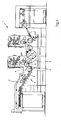
- FIG. 1 a machine 1 for processing a sheet-shaped substrate 2 is shown.
- the machine 1 is a printing press and comprises as substrate transport devices a chain conveyor 3 and a drum 4.
- the two printing material transport devices are assigned a first printing material guide device 5 and a second printing material guide device 6.
- the first Beffystoffleitvortechnik 5 has a planar guide surface 7 and is arranged below the chain conveyor 3.
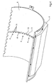
- the second Betikstoffleitvortechnik 6 has a concentrically curved with the drum 4 baffle 8 and is disposed below the drum 4.
- the Betikstoffleitvortechniken 5, 6 are Blas Kunststoffhimsten and serve to guide the transported past them by the Betikstofftransportvortechniken passing material 2 by means of the guide surfaces 7, 8 generated Blas Kunststoffpolster.
- the guide surfaces 7, 8 are facing the chain conveyor 3 and the drum 4.
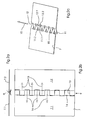
- the guide surface 7 is composed of a first piece 7.1 and a second piece 7.2.
- the pieces 7.1, 7.2 are made of sheet metal and are plate-shaped.
- the guide surface 7 is provided with a central nozzle row 9, which extends parallel to a transport direction 10 of the printing material 2.
- the first Piece 7.1 has a first substantially comb-shaped contour, ie, a first comb contour 11, and the second piece 7.2 has a second comb contour 12.
- the two comb contours 11, 12 are interlocked with each other, the tongues 11.1 of the first comb contour 11 in gaps 12.2 of the second Catch contour 12 engage and tongues 12.1 of the second comb contour 12 in gaps 11.2 of the first comb contour 11 engage when the pieces 7.1, 7.2 are assembled ready for use.
- the comb contours 11, 12 have been produced in a cutting along a meandering line 13 a plate in the two pieces 7.1, 7.2.
- the meander shape of the cutting line 13 is best in FIG. 2b recognizable, which is based on a relative to the guide surface 7 vertical viewing direction. From the FIG.
- the tongues 11.1, 12.1 are inclined relative to the guide surface 7 at an angle of less than 45 degrees.
- the tongues 11.1, 12.1 are inclined transversely to the transport direction 10 and along the row of nozzles 9 alternately to the left and to the right and have their inclinations obtained by a folding before the assembly of the two pieces 7.1, 7.2 and bending lines 14.
- Each of the bending lines 14 is located at the foot of the respective tongue 11.1, 12.1.
- the tongues 11.1, 12.1 and gaps 11.2, 12.2 together form nozzles 15 whose air flows 16 to side edges 17 (see. FIG. 3 ) of the printing material 2 are directed towards.
- the meandering cutting line 13 is executed only as a finite incision, so that webs 18 are left standing and serving as a workpiece plate is not severed over its entire length.
- the z. B. by means of a laser beam can be performed particularly quickly and precisely, the bending or tilting of the tongues 11.1, 12.1 of the nozzles 15, which are arranged on a common alignment line 19.
- This alignment line 19 extends centrally with respect to the substrate width b of the printing substrate 2.
- FIG. 4 illustrated second Beffystoffleitvoriques 6 differs from the in FIG. 3 shown modification of the first Beffystoffleitvortechnisch 5 essentially only in that the guide surface 8 is not made of a plate-shaped but from a cup-shaped (sheet) piece. Just as the guide surface 7 and the guide surface 8 is integrally formed.
- the introduced into the guide surface 8 nozzles 15 are grouped in a plurality of aligned nozzle rows 9. Each of the rows of nozzles 9 has its own meander-shaped cutting line 13 and is separated from its respectively adjacent row of nozzles 9 via a web 8 stabilizing the guide surface 8.
- the nozzle rows 9 extend longitudinally with respect to the substrate width b (see FIG. FIG. 3 ) in the middle.
Landscapes
- Engineering & Computer Science (AREA)
- Mechanical Engineering (AREA)
- Feeding Of Articles By Means Other Than Belts Or Rollers (AREA)
- Particle Formation And Scattering Control In Inkjet Printers (AREA)
- Impact Printers (AREA)
- Delivering By Means Of Belts And Rollers (AREA)
Applications Claiming Priority (2)
| Application Number | Priority Date | Filing Date | Title |
|---|---|---|---|
| DE2003144715 DE10344715A1 (de) | 2003-09-26 | 2003-09-26 | Vorrichtung zum Leiten eines Bedruckstoffes |
| DE10344715 | 2003-09-26 |
Publications (3)
| Publication Number | Publication Date |
|---|---|
| EP1518806A2 EP1518806A2 (de) | 2005-03-30 |
| EP1518806A3 EP1518806A3 (de) | 2008-01-09 |
| EP1518806B1 true EP1518806B1 (de) | 2012-11-21 |
Family
ID=34177970
Family Applications (1)
| Application Number | Title | Priority Date | Filing Date |
|---|---|---|---|
| EP20040104203 Expired - Lifetime EP1518806B1 (de) | 2003-09-26 | 2004-09-02 | Vorrichtung zum Leiten eines Bedruckstoffs |
Country Status (4)
| Country | Link |
|---|---|
| EP (1) | EP1518806B1 (enExample) |
| JP (1) | JP4460931B2 (enExample) |
| CN (1) | CN100484852C (enExample) |
| DE (1) | DE10344715A1 (enExample) |
Families Citing this family (3)
| Publication number | Priority date | Publication date | Assignee | Title |
|---|---|---|---|---|
| JP3224349U (ja) * | 2018-10-29 | 2019-12-12 | ハイデルベルガー ドルツクマシーネン アクチエンゲゼルシヤフトHeidelberger Druckmaschinen AG | 印刷ニップの手前にブロー装置を有する印刷機 |
| CN109679516B (zh) * | 2018-12-29 | 2021-08-10 | 络派科技(深圳)有限公司 | 一种软薄材料的复合方法 |
| FR3118895B1 (fr) * | 2021-01-18 | 2023-04-14 | Lectra | Elément modulaire de peigne pour machine de coupe automatique d’un matelas de feuilles de matériau |
Family Cites Families (14)
| Publication number | Priority date | Publication date | Assignee | Title |
|---|---|---|---|---|
| DE2135105B1 (de) * | 1971-07-14 | 1972-11-09 | Roland Offsetmaschf | Bogenauslegevorrichtung an Rotationsdruckmaschinen |
| DE2802610C2 (de) * | 1978-01-21 | 1983-05-05 | Vits-Maschinenbau Gmbh, 4018 Langenfeld | Blaskasten zum schwebenden Führen und/oder Fördern von Bahnen oder Bogen |
| US4427448A (en) | 1982-06-07 | 1984-01-24 | International Business Machines Corporation | Corrosion inhibiting compositions for metals |
| DE3626016A1 (de) * | 1986-07-31 | 1988-02-04 | Kurt Krieger | Vorrichtung zum beaufschlagen von materialbahnen mit stroemungsmedium |
| DD285072A5 (de) * | 1989-06-16 | 1990-12-05 | Veb Polygraph "Werner Lamberz",Dd | Blaseinrichtung |
| DE4033642A1 (de) * | 1990-10-23 | 1992-04-30 | Hoechst Ag | Leitvorrichtung zum fuehren, aus- und/oder umlenken einer materialbahn |
| DE4406847C2 (de) * | 1994-03-03 | 1997-07-10 | Koenig & Bauer Albert Ag | Vorrichtung zum schwebenden Führen von Bogen oder Bahnen |
| DE4447963B4 (de) * | 1994-08-03 | 2005-12-29 | Heidelberger Druckmaschinen Ag | Einrichtung zum berührungsfreien Führen bogenförmigen Materials |
| DE19545799C1 (de) * | 1995-12-08 | 1997-01-16 | Kba Planeta Ag | Bogenführungssystem an Bogenführungszylindern in Druckmaschinen |
| JPH1086330A (ja) | 1996-09-03 | 1998-04-07 | Heidelberger Druckmas Ag | 枚葉紙印刷機で枚葉紙を無接触に案内する装置 |
| DE29615294U1 (de) * | 1996-09-03 | 1996-10-24 | Heidelberger Druckmaschinen Ag, 69115 Heidelberg | Vorrichtung zur berührungslosen Bogenführung in einer Bogendruckmaschine |
| DE29817317U1 (de) * | 1998-09-26 | 1998-11-19 | MAN Roland Druckmaschinen AG, 63075 Offenbach | Bogenführungseinrichtung mit einer Führungsfläche in einer Druckmaschine |
| DE19905095C2 (de) * | 1999-02-09 | 2001-02-22 | Roland Man Druckmasch | Bogenführungseinrichtung für eine Druckmaschine |
| DE10057570B4 (de) * | 1999-12-15 | 2005-11-24 | Heidelberger Druckmaschinen Ag | Leitvorrichtung einer flächige Bedruckstoffe verarbeitenden Maschine |
-
2003
- 2003-09-26 DE DE2003144715 patent/DE10344715A1/de not_active Withdrawn
-
2004
- 2004-03-26 JP JP2004092798A patent/JP4460931B2/ja not_active Expired - Fee Related
- 2004-09-02 EP EP20040104203 patent/EP1518806B1/de not_active Expired - Lifetime
- 2004-09-27 CN CNB2004100117670A patent/CN100484852C/zh not_active Expired - Fee Related
Also Published As
| Publication number | Publication date |
|---|---|
| CN1600660A (zh) | 2005-03-30 |
| EP1518806A2 (de) | 2005-03-30 |
| CN100484852C (zh) | 2009-05-06 |
| JP4460931B2 (ja) | 2010-05-12 |
| DE10344715A1 (de) | 2005-04-21 |
| JP2005104725A (ja) | 2005-04-21 |
| EP1518806A3 (de) | 2008-01-09 |
Similar Documents
| Publication | Publication Date | Title |
|---|---|---|
| EP2159173B1 (de) | Transportvorrichtung und Verfahren zum geordneten Transport von Artikeln | |
| DE60102087T2 (de) | Verfahren zum Stanzen von Teilen von Riemen für stufenlos regelbares Getriebe | |
| DE102013214404A1 (de) | Werkstückauflage für den Einsatz in einer Bearbeitungsmaschine | |
| DE19643261A1 (de) | Verfahren und Vorrichtung zum Einrichten von paarweise zusammenwirkenden Werkzeugen | |
| EP3165660B1 (de) | Nadelbrett | |
| EP1518806B1 (de) | Vorrichtung zum Leiten eines Bedruckstoffs | |
| DE19906956B4 (de) | Stent sowie Verfahren zur Herstellung eines Stents | |
| EP0962269A2 (de) | Verfahren und Vorrichtung zur Herstellung von Bundlagern | |
| DE69205620T2 (de) | Stanzvorrichtung und Verfahren. | |
| DE112006001387B4 (de) | Verfahren zur Herstellung einer Platte, sowie Folgeschneidwerkzeuganlage | |
| EP2047020B1 (de) | Vorrichtung zur herstellung von durchbrochenen vliesstoffen | |
| WO2023247461A1 (de) | Verfahren zum einstechen eines laserstrahls einer laserschneidmaschine in ein plattenförmiges werkstück zum ausschneiden eines werkstückteils aus dem werkstück entlang einer auf dem werkstück vorgegebenen schneidkontur | |
| DE102008009856A1 (de) | Halbring einer Anlaufscheibe und ein Verfahren zur Herstellung derartiger Anlaufscheiben-Halbringe | |
| EP3889330B1 (de) | Textilwerkzeugteilepaar und verfahren zur bestückung einer textilmaschine | |
| DE10322302B4 (de) | Anlage zur Herstellung von Platinen aus bandförmigem Material | |
| DE4022965C1 (enExample) | ||
| EP0866526B1 (de) | Trägergurt für Kontaktstifte und Verfahren zu dessen Herstellung | |
| WO2018073432A1 (de) | Werkzeug und verfahren zum entgraten eines ojektes | |
| DE2811494C2 (enExample) | ||
| DE102016010625A1 (de) | Verfahren zum maschinellen Stanzen von Nutzen sowie zugehörige Vorrichtung, Faltschachtel und Kodierungsverfahren | |
| DE102017129367A1 (de) | Trägerelement zur Aufnahme von Stanzlinien, das Trägerelement umfassende Stanzform und Verfahren zur Herstellung der Stanzform | |
| EP1184127A1 (de) | Bearbeitungsvorrichtung für flache Bögen | |
| DE102023114964A1 (de) | Bearbeitungswerkzeug | |
| DE10147645A1 (de) | Schallabschirmelement und Verfahren zur Herstellung | |
| DE2602887A1 (de) | Wellblech und verfahren zu dessen herstellung |
Legal Events
| Date | Code | Title | Description |
|---|---|---|---|
| PUAI | Public reference made under article 153(3) epc to a published international application that has entered the european phase |
Free format text: ORIGINAL CODE: 0009012 |
|
| AK | Designated contracting states |
Kind code of ref document: A2 Designated state(s): AT BE BG CH CY CZ DE DK EE ES FI FR GB GR HU IE IT LI LU MC NL PL PT RO SE SI SK TR |
|
| AX | Request for extension of the european patent |
Extension state: AL HR LT LV MK |
|
| PUAL | Search report despatched |
Free format text: ORIGINAL CODE: 0009013 |
|
| AK | Designated contracting states |
Kind code of ref document: A3 Designated state(s): AT BE BG CH CY CZ DE DK EE ES FI FR GB GR HU IE IT LI LU MC NL PL PT RO SE SI SK TR |
|
| AX | Request for extension of the european patent |
Extension state: AL HR LT LV MK |
|
| 17P | Request for examination filed |
Effective date: 20080709 |
|
| AKX | Designation fees paid |
Designated state(s): AT BE BG CH CY CZ DE DK EE ES FI FR GB GR HU IE IT LI LU MC NL PL PT RO SE SI SK TR |
|
| GRAP | Despatch of communication of intention to grant a patent |
Free format text: ORIGINAL CODE: EPIDOSNIGR1 |
|
| RIN1 | Information on inventor provided before grant (corrected) |
Inventor name: BACHMEIER, PETER Inventor name: LIPPARDT, SVEN Inventor name: THOMA, PETER Inventor name: KERPE, SVEN |
|
| GRAS | Grant fee paid |
Free format text: ORIGINAL CODE: EPIDOSNIGR3 |
|
| GRAA | (expected) grant |
Free format text: ORIGINAL CODE: 0009210 |
|
| AK | Designated contracting states |
Kind code of ref document: B1 Designated state(s): AT BE BG CH CY CZ DE DK EE ES FI FR GB GR HU IE IT LI LU MC NL PL PT RO SE SI SK TR |
|
| REG | Reference to a national code |
Ref country code: GB Ref legal event code: FG4D Free format text: NOT ENGLISH |
|
| REG | Reference to a national code |
Ref country code: CH Ref legal event code: EP |
|
| REG | Reference to a national code |
Ref country code: AT Ref legal event code: REF Ref document number: 584960 Country of ref document: AT Kind code of ref document: T Effective date: 20121215 |
|
| REG | Reference to a national code |
Ref country code: IE Ref legal event code: FG4D Free format text: LANGUAGE OF EP DOCUMENT: GERMAN |
|
| REG | Reference to a national code |
Ref country code: DE Ref legal event code: R096 Ref document number: 502004013880 Country of ref document: DE Effective date: 20130117 |
|
| REG | Reference to a national code |
Ref country code: NL Ref legal event code: VDEP Effective date: 20121121 |
|
| PG25 | Lapsed in a contracting state [announced via postgrant information from national office to epo] |
Ref country code: FI Free format text: LAPSE BECAUSE OF FAILURE TO SUBMIT A TRANSLATION OF THE DESCRIPTION OR TO PAY THE FEE WITHIN THE PRESCRIBED TIME-LIMIT Effective date: 20121121 Ref country code: ES Free format text: LAPSE BECAUSE OF FAILURE TO SUBMIT A TRANSLATION OF THE DESCRIPTION OR TO PAY THE FEE WITHIN THE PRESCRIBED TIME-LIMIT Effective date: 20130304 Ref country code: SE Free format text: LAPSE BECAUSE OF FAILURE TO SUBMIT A TRANSLATION OF THE DESCRIPTION OR TO PAY THE FEE WITHIN THE PRESCRIBED TIME-LIMIT Effective date: 20121121 |
|
| PG25 | Lapsed in a contracting state [announced via postgrant information from national office to epo] |
Ref country code: PL Free format text: LAPSE BECAUSE OF FAILURE TO SUBMIT A TRANSLATION OF THE DESCRIPTION OR TO PAY THE FEE WITHIN THE PRESCRIBED TIME-LIMIT Effective date: 20121121 Ref country code: PT Free format text: LAPSE BECAUSE OF FAILURE TO SUBMIT A TRANSLATION OF THE DESCRIPTION OR TO PAY THE FEE WITHIN THE PRESCRIBED TIME-LIMIT Effective date: 20130321 Ref country code: SI Free format text: LAPSE BECAUSE OF FAILURE TO SUBMIT A TRANSLATION OF THE DESCRIPTION OR TO PAY THE FEE WITHIN THE PRESCRIBED TIME-LIMIT Effective date: 20121121 Ref country code: GR Free format text: LAPSE BECAUSE OF FAILURE TO SUBMIT A TRANSLATION OF THE DESCRIPTION OR TO PAY THE FEE WITHIN THE PRESCRIBED TIME-LIMIT Effective date: 20130222 |
|
| PG25 | Lapsed in a contracting state [announced via postgrant information from national office to epo] |
Ref country code: BG Free format text: LAPSE BECAUSE OF FAILURE TO SUBMIT A TRANSLATION OF THE DESCRIPTION OR TO PAY THE FEE WITHIN THE PRESCRIBED TIME-LIMIT Effective date: 20130221 Ref country code: SK Free format text: LAPSE BECAUSE OF FAILURE TO SUBMIT A TRANSLATION OF THE DESCRIPTION OR TO PAY THE FEE WITHIN THE PRESCRIBED TIME-LIMIT Effective date: 20121121 Ref country code: DK Free format text: LAPSE BECAUSE OF FAILURE TO SUBMIT A TRANSLATION OF THE DESCRIPTION OR TO PAY THE FEE WITHIN THE PRESCRIBED TIME-LIMIT Effective date: 20121121 Ref country code: EE Free format text: LAPSE BECAUSE OF FAILURE TO SUBMIT A TRANSLATION OF THE DESCRIPTION OR TO PAY THE FEE WITHIN THE PRESCRIBED TIME-LIMIT Effective date: 20121121 Ref country code: CZ Free format text: LAPSE BECAUSE OF FAILURE TO SUBMIT A TRANSLATION OF THE DESCRIPTION OR TO PAY THE FEE WITHIN THE PRESCRIBED TIME-LIMIT Effective date: 20121121 |
|
| PG25 | Lapsed in a contracting state [announced via postgrant information from national office to epo] |
Ref country code: RO Free format text: LAPSE BECAUSE OF FAILURE TO SUBMIT A TRANSLATION OF THE DESCRIPTION OR TO PAY THE FEE WITHIN THE PRESCRIBED TIME-LIMIT Effective date: 20121121 Ref country code: NL Free format text: LAPSE BECAUSE OF FAILURE TO SUBMIT A TRANSLATION OF THE DESCRIPTION OR TO PAY THE FEE WITHIN THE PRESCRIBED TIME-LIMIT Effective date: 20121121 Ref country code: IT Free format text: LAPSE BECAUSE OF FAILURE TO SUBMIT A TRANSLATION OF THE DESCRIPTION OR TO PAY THE FEE WITHIN THE PRESCRIBED TIME-LIMIT Effective date: 20121121 |
|
| PLBE | No opposition filed within time limit |
Free format text: ORIGINAL CODE: 0009261 |
|
| STAA | Information on the status of an ep patent application or granted ep patent |
Free format text: STATUS: NO OPPOSITION FILED WITHIN TIME LIMIT |
|
| 26N | No opposition filed |
Effective date: 20130822 |
|
| REG | Reference to a national code |
Ref country code: DE Ref legal event code: R097 Ref document number: 502004013880 Country of ref document: DE Effective date: 20130822 |
|
| BERE | Be: lapsed |
Owner name: HEIDELBERGER DRUCKMASCHINEN A.G. Effective date: 20130930 |
|
| PG25 | Lapsed in a contracting state [announced via postgrant information from national office to epo] |
Ref country code: MC Free format text: LAPSE BECAUSE OF FAILURE TO SUBMIT A TRANSLATION OF THE DESCRIPTION OR TO PAY THE FEE WITHIN THE PRESCRIBED TIME-LIMIT Effective date: 20121121 |
|
| REG | Reference to a national code |
Ref country code: CH Ref legal event code: PL |
|
| GBPC | Gb: european patent ceased through non-payment of renewal fee |
Effective date: 20130902 |
|
| REG | Reference to a national code |
Ref country code: FR Ref legal event code: ST Effective date: 20140530 |
|
| REG | Reference to a national code |
Ref country code: IE Ref legal event code: MM4A |
|
| PG25 | Lapsed in a contracting state [announced via postgrant information from national office to epo] |
Ref country code: GB Free format text: LAPSE BECAUSE OF NON-PAYMENT OF DUE FEES Effective date: 20130902 Ref country code: CH Free format text: LAPSE BECAUSE OF NON-PAYMENT OF DUE FEES Effective date: 20130930 Ref country code: BE Free format text: LAPSE BECAUSE OF NON-PAYMENT OF DUE FEES Effective date: 20130930 Ref country code: IE Free format text: LAPSE BECAUSE OF NON-PAYMENT OF DUE FEES Effective date: 20130902 Ref country code: LI Free format text: LAPSE BECAUSE OF NON-PAYMENT OF DUE FEES Effective date: 20130930 |
|
| PG25 | Lapsed in a contracting state [announced via postgrant information from national office to epo] |
Ref country code: FR Free format text: LAPSE BECAUSE OF NON-PAYMENT OF DUE FEES Effective date: 20130930 |
|
| REG | Reference to a national code |
Ref country code: AT Ref legal event code: MM01 Ref document number: 584960 Country of ref document: AT Kind code of ref document: T Effective date: 20130902 |
|
| PG25 | Lapsed in a contracting state [announced via postgrant information from national office to epo] |
Ref country code: AT Free format text: LAPSE BECAUSE OF NON-PAYMENT OF DUE FEES Effective date: 20130902 |
|
| PG25 | Lapsed in a contracting state [announced via postgrant information from national office to epo] |
Ref country code: TR Free format text: LAPSE BECAUSE OF FAILURE TO SUBMIT A TRANSLATION OF THE DESCRIPTION OR TO PAY THE FEE WITHIN THE PRESCRIBED TIME-LIMIT Effective date: 20121121 Ref country code: CY Free format text: LAPSE BECAUSE OF FAILURE TO SUBMIT A TRANSLATION OF THE DESCRIPTION OR TO PAY THE FEE WITHIN THE PRESCRIBED TIME-LIMIT Effective date: 20121121 |
|
| PG25 | Lapsed in a contracting state [announced via postgrant information from national office to epo] |
Ref country code: HU Free format text: LAPSE BECAUSE OF FAILURE TO SUBMIT A TRANSLATION OF THE DESCRIPTION OR TO PAY THE FEE WITHIN THE PRESCRIBED TIME-LIMIT; INVALID AB INITIO Effective date: 20040902 Ref country code: LU Free format text: LAPSE BECAUSE OF NON-PAYMENT OF DUE FEES Effective date: 20130902 |
|
| PGFP | Annual fee paid to national office [announced via postgrant information from national office to epo] |
Ref country code: DE Payment date: 20200930 Year of fee payment: 17 |
|
| REG | Reference to a national code |
Ref country code: DE Ref legal event code: R119 Ref document number: 502004013880 Country of ref document: DE |
|
| PG25 | Lapsed in a contracting state [announced via postgrant information from national office to epo] |
Ref country code: DE Free format text: LAPSE BECAUSE OF NON-PAYMENT OF DUE FEES Effective date: 20220401 |