EP1518766B1 - Verfahren zur Steuerung eines Sicherheitsgurtaufrollgeräts und Vorrichtung dafür. - Google Patents
Verfahren zur Steuerung eines Sicherheitsgurtaufrollgeräts und Vorrichtung dafür. Download PDFInfo
- Publication number
- EP1518766B1 EP1518766B1 EP04017962A EP04017962A EP1518766B1 EP 1518766 B1 EP1518766 B1 EP 1518766B1 EP 04017962 A EP04017962 A EP 04017962A EP 04017962 A EP04017962 A EP 04017962A EP 1518766 B1 EP1518766 B1 EP 1518766B1
- Authority
- EP
- European Patent Office
- Prior art keywords
- motor
- seatbelt
- current
- retraction
- value
- Prior art date
- Legal status (The legal status is an assumption and is not a legal conclusion. Google has not performed a legal analysis and makes no representation as to the accuracy of the status listed.)
- Expired - Lifetime
Links
- 238000000034 method Methods 0.000 title claims description 18
- 230000007246 mechanism Effects 0.000 claims description 7
- 230000009467 reduction Effects 0.000 description 4
- 210000000481 breast Anatomy 0.000 description 3
- 238000009331 sowing Methods 0.000 description 3
- 230000001133 acceleration Effects 0.000 description 2
- 230000004913 activation Effects 0.000 description 2
- 238000010586 diagram Methods 0.000 description 2
- 230000008859 change Effects 0.000 description 1
- 230000001419 dependent effect Effects 0.000 description 1
- 230000007257 malfunction Effects 0.000 description 1
Images



Classifications
-
- B—PERFORMING OPERATIONS; TRANSPORTING
- B60—VEHICLES IN GENERAL
- B60R—VEHICLES, VEHICLE FITTINGS, OR VEHICLE PARTS, NOT OTHERWISE PROVIDED FOR
- B60R22/00—Safety belts or body harnesses in vehicles
- B60R22/34—Belt retractors, e.g. reels
- B60R22/44—Belt retractors, e.g. reels with means for reducing belt tension during use under normal conditions
-
- B—PERFORMING OPERATIONS; TRANSPORTING
- B60—VEHICLES IN GENERAL
- B60R—VEHICLES, VEHICLE FITTINGS, OR VEHICLE PARTS, NOT OTHERWISE PROVIDED FOR
- B60R22/00—Safety belts or body harnesses in vehicles
- B60R22/34—Belt retractors, e.g. reels
- B60R22/44—Belt retractors, e.g. reels with means for reducing belt tension during use under normal conditions
- B60R2022/442—Belt retractors, e.g. reels with means for reducing belt tension during use under normal conditions using one spring and one additional retraction device in parallel
- B60R2022/444—Belt retractors, e.g. reels with means for reducing belt tension during use under normal conditions using one spring and one additional retraction device in parallel the additional retraction device being an electric actuator
-
- B—PERFORMING OPERATIONS; TRANSPORTING
- B60—VEHICLES IN GENERAL
- B60R—VEHICLES, VEHICLE FITTINGS, OR VEHICLE PARTS, NOT OTHERWISE PROVIDED FOR
- B60R22/00—Safety belts or body harnesses in vehicles
- B60R22/34—Belt retractors, e.g. reels
- B60R22/44—Belt retractors, e.g. reels with means for reducing belt tension during use under normal conditions
- B60R2022/4446—Belt retractors, e.g. reels with means for reducing belt tension during use under normal conditions using one spring and one additional retraction device in series
- B60R2022/4466—Belt retractors, e.g. reels with means for reducing belt tension during use under normal conditions using one spring and one additional retraction device in series the additional retraction device being an electric actuator
-
- B—PERFORMING OPERATIONS; TRANSPORTING
- B60—VEHICLES IN GENERAL
- B60R—VEHICLES, VEHICLE FITTINGS, OR VEHICLE PARTS, NOT OTHERWISE PROVIDED FOR
- B60R22/00—Safety belts or body harnesses in vehicles
- B60R22/34—Belt retractors, e.g. reels
- B60R22/44—Belt retractors, e.g. reels with means for reducing belt tension during use under normal conditions
- B60R2022/4473—Belt retractors, e.g. reels with means for reducing belt tension during use under normal conditions using an electric retraction device
-
- B—PERFORMING OPERATIONS; TRANSPORTING
- B60—VEHICLES IN GENERAL
- B60R—VEHICLES, VEHICLE FITTINGS, OR VEHICLE PARTS, NOT OTHERWISE PROVIDED FOR
- B60R22/00—Safety belts or body harnesses in vehicles
- B60R22/34—Belt retractors, e.g. reels
- B60R22/44—Belt retractors, e.g. reels with means for reducing belt tension during use under normal conditions
- B60R2022/4486—Belt retractors, e.g. reels with means for reducing belt tension during use under normal conditions for cancelling the belt tension
Definitions
- the present invention relates to a method of controlling a seatbelt retracting device having a mechanism for retracting a seatbelt by a motor and a respective seatbelt retracting device.
- a seatbelt retracting device mounted to a motor vehicle or the like has a function to absorb the portion of a seatbelt which is excessively withdrawn by an occupant being seated after having withdrawn the seat belt and fastened a tongue to a buckle device.
- a single return spring is employed in the seatbelt retracting device in the related art.
- a seatbelt retracting device for solving the above described problems, a device in which the seatbelt is retracted by a motor, or the combination of the motor and a return spring is proposed, which is disclosed in Japanese Unexamined Patent Application Publication No. 2001-225720.
- the seatbelt retracting device having a mechanism for retracting the seatbelt by the use of the motor as described above is also described in Japanese Unexamined Patent Application Publication No. 11-301407, and in Japanese Unexamined Patent Application Publication No. 11-334533.
- the seatbelt retracting device with a motor in the related art described above, it generally controls the power source of the motor to be turned off at the moment when retraction of the seatbelt is completed.
- the power source of the motor is left on when retraction of the seatbelt is completed, not only the power source of a battery is wasted, but also the motor is overheated. Therefore, there arises another problem that a motor having a heat resistant property correspondingly has to be employed.
- a current value at which retraction is recognized to be completed is set to a large value for ensuring retraction of the seatbelt.
- the part of the body of the occupant is tightened by a retraction force of the motor, which may give a feeling of pressure to the occupant.
- the seatbelt retracting device by itself may be deteriorated and hence a torque required for drive increases, or when the output of the motor is lowered, it may be recognized that retraction is completed before retraction is actually completed and hence the power distribution to the motor is stopped, which results in insufficient retraction.
- an object of the present invention is to provide a method of controlling a seatbelt retracting device with a motor and a respective seatbelt retracting device, in which positive retraction can be achieved in the normal state, a significant feeling of pressure is prevented when part of the body of the occupants is caught in the seatbelt, and the seatbelt can be withdrawn with a small force even during retraction.
- the first aspect of the invention is a method of controlling a seatbelt retracting device with a motor including a mechanism for retracting a seatbelt by the motor characterized in that the motor is adapted to be stopped when the rate of increase in current flowing to the motor reaches or exceeds a predetermined value.
- the motor is adapted to be stopped when the rate of increase in current flowing to the motor reaches or exceeds the predetermined value.
- the rate of increase in current flowing to the motor reaches or exceeds the predetermined value.
- the second measure is the first measure characterized in that the motor is stopped also when a current value flowing to the motor reaches or exceeds a predetermined value.
- the motor since the motor is adapted to be stopped also when the current value flowing to the motor reaches or exceeds the predetermined value, by setting the predetermined value to a value close to the saturation value of the current to the motor, the power distribution to the motor can be stopped upon completion of retraction even in such a case.
- the third measure is the first measure or the second measure, characterized in that control to stop the motor is not executed for a predetermined period from the moment when the motor is activated.
- a counter electromotive force of the motor is small immediately after activation of the motor, an accelerated current flows and the current flowing to the motor abruptly increases. In some case, it exceeds the threshold of the rate of increase in current according to the above-described first measure and the second measure and hence the motor may stop. According to this measure, since control to stop the motor is not executed for the predetermined period from the moment when the motor is activated, malfunction due to the accelerated current flown immediately after the activation of the motor can be positively prevented. Furthermore, a seatbelt retracting device is provided being adapted to carry out the above described method of the present invention by using respective motor current detecting means and motor control means.
- a method of controlling a seatbelt retracting device with a motor in which positive retraction can be achieved in the normal state a significant feeling of pressure is prevented when part of the body of the occupant is caught in the seatbelt, and the seatbelt can be withdrawn with a small force even during retraction.
- Fig. 1 is a schematic diagram showing an example of the structure of a device which implements a method of controlling according to the embodiment of the present invention.
- reference numeral 1 designates a seatbelt retractor (a main body of a seatbelt retracting device)
- reference numeral 2 designates a spring mechanism
- reference numeral 3 designates a clutch
- reference numeral 4 designates a reduction gear
- reference numeral 5 designates a motor
- reference numeral 6 designates a motor control circuit
- reference numeral 7 designates a current detecting circuit.
- the seatbelt retractor 1 is connected to the spring mechanism 2, and is connected to the reduction gear 4 via the clutch 3.
- the reduction gear 4 is directly connected to the motor 5. Power distribution to the motor 5 and ON-OFF of the clutch 3 are controlled by the motor control circuit 6.
- the motor control circuit 6 When an instruction to drive the seatbelt retractor by the motor 5 is issued to the motor control circuit 6 via an external signal, not shown, the motor control circuit 6 starts power distribution to the motor 5, and turns the clutch 3 into the "ON" state, that is, brings the seatbelt retractor 1 and the reduction gear 4 into the coupled state.
- the current distributed to the motor 5 is detected by the current detecting circuit 7 (current detecting means), and a feedback is given to the motor control circuit 6 (motor control means).
- the motor control circuit 6 reads the current value detected by the current detecting circuit 7 at predetermined time intervals, and calculates the difference value with respect to the previously read value. Then, the power distribution to the motor 5 is stopped according to a mode selected in advance out of three modes shown below.
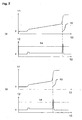
- FIG. 2 is a drawing showing an example of the operation of the motor control circuit 6 in Mode 1.
- (a) shows the current value 11 and the rate 12 of increase in current with time 13 when retraction is being performed in a normal way
- (b) shows the current value and the rate of increase in current with time when a part of the body (arm, for example) of an occupant is caught in the seatbelt during retraction.
- Solid lines represent the actual current value and the rate of increase in current
- broken lines represent the current value and the rate of increase in current when the power distribution is not stopped.
- the motor control circuit 6 obtains the rate of increase in current by differentiating the output of the current detecting circuit 7 or calculating the difference with respect to the previous measured value.
- the motor control circuit 6 stops the power distribution to the motor 5 when the obtained rate of increase in current exceeds the predetermined threshold 14, i.e. an instruction to stop power distribution is issued which is designated by reference numeral 15. In this manner, the power distribution to the motor 5 can be stopped when retraction of the seatbelt is completed.
- Fig. 3 is a drawing showing the operation of the motor control circuit 6 when the seatbelt retractor 1 is deteriorated and hence the torque required for retracting the seatbelt is increased, or when the motor 5 is deteriorated and hence the output torque is lowered.
- the control method of Mode 2 is used, and the power distribution to the motor 5 is stopped also in the case where the current value 11 itself exceeds the predetermined threshold 14 in addition to the case where the rate of increase in current exceeds the predetermined threshold.
- the threshold of the current value is preferably slightly smaller than the saturation value of the current. In other words, secondary control such that the power distribution to the motor 5 is stopped in a state in which the change of the rate of increase in current cannot be increased because the current value is increased to the value near the saturation value is preferably employed.
- Fig. 4 is an explanatory drawing showing control of Mode 3.
- the accelerated current 11 generated when the motor 5 is energized is significant depending on the specification of the motor 5, and hence the rate of increase in current 12 exceeds the predetermined threshold which is set in Mode 1 in the state of initial acceleration as shown in Fig. 4, i.e. an instruction to stop power distribution in Mode 1 is issued which is designated by reference numeral 15.
- an instruction to stop power distribution in Mode 1 is issued which is designated by reference numeral 15.
- the power distribution to the motor 5 is stopped, and hence the actual retracting operation cannot be performed normally.
- control to stop the power distribution to the motor 5 is not executed in the initial driving stage of the motor 5, that is, for a predetermined period (preferably, the time period slightly longer than the period until the acceleration is completed) from the moment when the power distribution to the motor 5 is started.
- Mode 1 the motor is driven only in the range indicated by the solid line shown in Fig. 4.
- Mode 3 the power distribution to the motor 5 is stopped when retraction as shown by the broken line is proceeded and then retraction is completed as usual, or a part of the body (arm, for example) of the occupant is caught in the seatbelt, i.e. as designated by reference numeral 17 an instruction to stop power distribution in Mode 3 is issued.
Landscapes
- Engineering & Computer Science (AREA)
- Mechanical Engineering (AREA)
- Automotive Seat Belt Assembly (AREA)
Claims (5)
- Verfahren zur Steuerung einer Sitzgurtaufrollvorrichtung, welche einen Motor (5) und einen Mechanismus (1), um einen Sitzgurt durch den Motor (5) zurückzuziehen, umfasst,
dadurch gekennzeichnet,
dass der Motor (5) gestoppt wird, wenn eine Anstiegsrate (12) bei einem Strom, welcher zu dem Motor (5) fließt, einen vorbestimmten Wert (14) erreicht oder übersteigt. - Verfahren zum Steuern einer Sitzgurtaufrollvorrichtung nach Anspruch 1, dadurch gekennzeichnet, dass der Motor (5) auch gestoppt wird, wenn ein Stromwert (11), welcher zu dem Motor (5) fließt, einen vorbestimmten Wert (14) erreicht oder übersteigt.
- Verfahren zum Steuern einer Sitzgurtaufrollvorrichtung nach Anspruch 1 oder Anspruch 2, dadurch gekennzeichnet, dass eine Steuerung, um den Motor (5) zu stoppen, für eine vorbestimmte Periode von dem Moment an, wenn der Motor (5) aktiviert wird, nicht betrieben wird.
- Sitzgurtaufrollvorrichtung umfassend
einen Motor (5), und
einen Mechanismus (1), um einen Sitzgurt durch den Motor (5) zurückzuziehen,
gekennzeichnet durch
Stromerfassungsmittel (7), um einen Strom, welcher zu dem Motor (5) fließt, zu erfassen, und
Motorsteuermittel (6), welche derart ausgestaltet sind, dass sie den Motor (5) stoppen, wenn eine Anstiegsrate (12) des Stroms, welcher zu dem Motor (5) fließt, einen vorbestimmten Wert erreicht oder übersteigt. - Sitzgurtaufrollvorrichtung nach Anspruch 4, dadurch gekennzeichnet, dass die Motorsteuermittel (6) derart ausgestaltet sind, dass sie das Verfahren nach einem der Ansprüche 1-3 ausführen.
Applications Claiming Priority (2)
| Application Number | Priority Date | Filing Date | Title |
|---|---|---|---|
| JP2003332854 | 2003-09-25 | ||
| JP2003332854A JP4472299B2 (ja) | 2003-09-25 | 2003-09-25 | モータ付シートベルト巻き取り装置の制御方法及び装置 |
Publications (2)
| Publication Number | Publication Date |
|---|---|
| EP1518766A1 EP1518766A1 (de) | 2005-03-30 |
| EP1518766B1 true EP1518766B1 (de) | 2006-09-13 |
Family
ID=34191472
Family Applications (1)
| Application Number | Title | Priority Date | Filing Date |
|---|---|---|---|
| EP04017962A Expired - Lifetime EP1518766B1 (de) | 2003-09-25 | 2004-07-29 | Verfahren zur Steuerung eines Sicherheitsgurtaufrollgeräts und Vorrichtung dafür. |
Country Status (5)
| Country | Link |
|---|---|
| US (2) | US7251111B2 (de) |
| EP (1) | EP1518766B1 (de) |
| JP (1) | JP4472299B2 (de) |
| CN (1) | CN100369773C (de) |
| DE (1) | DE602004002359T2 (de) |
Families Citing this family (18)
| Publication number | Priority date | Publication date | Assignee | Title |
|---|---|---|---|---|
| DE10160071B4 (de) * | 2001-12-06 | 2007-01-18 | Daimlerchrysler Ag | Verfahren zur Ansteuerung eines reversiblen Gurtstraffers |
| JP4371365B2 (ja) * | 2004-05-13 | 2009-11-25 | タカタ株式会社 | シートベルト巻き取り装置における巻き取り制御方法、及びシートベルト装置 |
| US9539981B2 (en) * | 2004-10-19 | 2017-01-10 | Autoliv Development Ab | Seat belt retractor, control method thereof, and seat belt device |
| JP2006282015A (ja) * | 2005-03-31 | 2006-10-19 | Takata Corp | シートベルトリトラクタ、シートベルト装置、シートベルト装置付車両 |
| EP1712435A3 (de) * | 2005-04-14 | 2006-11-22 | Takata Corporation | Sicherheitsgurtaufroller, Sicherheitsgurtvorrichtung und Fahrzeug mit Sicherheitsgurtvorrichtung |
| JP2006298142A (ja) * | 2005-04-20 | 2006-11-02 | Takata Corp | シートベルトリトラクタ、シートベルト装置、シートベルト装置付車両 |
| JP4640963B2 (ja) * | 2005-08-04 | 2011-03-02 | タカタ株式会社 | シートベルトリトラクタおよびこれを備えたシートベルト装置 |
| JP4714525B2 (ja) * | 2005-08-05 | 2011-06-29 | タカタ株式会社 | シートベルトリトラクタ、シートベルト装置、シートベルト装置付車両 |
| JP4653592B2 (ja) * | 2005-08-22 | 2011-03-16 | 株式会社東海理化電機製作所 | モータリトラクタ |
| JP2007062421A (ja) * | 2005-08-29 | 2007-03-15 | Takata Corp | シートベルト装置、車両 |
| JP4704927B2 (ja) * | 2006-02-14 | 2011-06-22 | 株式会社東海理化電機製作所 | モータリトラクタ |
| JP2008024133A (ja) * | 2006-07-20 | 2008-02-07 | Tokai Rika Co Ltd | シートベルト装置 |
| JP4959296B2 (ja) * | 2006-11-10 | 2012-06-20 | 本田技研工業株式会社 | 車両のシートベルト装置 |
| JP4975483B2 (ja) * | 2007-03-01 | 2012-07-11 | 本田技研工業株式会社 | シートベルト装置 |
| JP4889601B2 (ja) * | 2007-09-12 | 2012-03-07 | 本田技研工業株式会社 | 車両のシートベルト装置 |
| JP4492732B2 (ja) * | 2008-05-13 | 2010-06-30 | 株式会社デンソー | モータ駆動装置、及び駆動装置状態判定方法 |
| CN102555984A (zh) * | 2012-03-09 | 2012-07-11 | 许晓聪 | 一种安全带监测装置 |
| US10232940B2 (en) * | 2016-09-09 | 2019-03-19 | Wing Aviation Llc | Methods and systems for raising and lowering a payload |
Family Cites Families (6)
| Publication number | Priority date | Publication date | Assignee | Title |
|---|---|---|---|---|
| JP4662225B2 (ja) | 2001-09-12 | 2011-03-30 | タカタ株式会社 | シートベルト巻取装置 |
| JP3761717B2 (ja) * | 1998-05-29 | 2006-03-29 | エヌエスケー・オートリブ株式会社 | 車両用乗員拘束保護装置 |
| US6485057B1 (en) * | 1997-12-16 | 2002-11-26 | Nsk Autoliv Co., Ltd. | Automotive passenger restraint and protection apparatus and seatbelt protraction and retraction amount-detecting device |
| JP3554484B2 (ja) * | 1998-04-24 | 2004-08-18 | エヌエスケー・オートリブ株式会社 | 車両用乗員拘束保護装置 |
| JP4800471B2 (ja) * | 1999-11-02 | 2011-10-26 | タカタ株式会社 | シートベルト巻取装置 |
| US6494395B1 (en) | 1999-11-02 | 2002-12-17 | Takata Corporation | Seat belt retractor with clutch mechanism |
-
2003
- 2003-09-25 JP JP2003332854A patent/JP4472299B2/ja not_active Expired - Fee Related
-
2004
- 2004-06-17 US US10/868,932 patent/US7251111B2/en not_active Expired - Lifetime
- 2004-07-29 EP EP04017962A patent/EP1518766B1/de not_active Expired - Lifetime
- 2004-07-29 DE DE602004002359T patent/DE602004002359T2/de not_active Expired - Lifetime
- 2004-08-05 CN CNB2004100558866A patent/CN100369773C/zh not_active Expired - Fee Related
-
2007
- 2007-07-24 US US11/878,363 patent/US7545613B2/en not_active Expired - Fee Related
Also Published As
| Publication number | Publication date |
|---|---|
| JP4472299B2 (ja) | 2010-06-02 |
| DE602004002359T2 (de) | 2007-09-13 |
| US7251111B2 (en) | 2007-07-31 |
| EP1518766A1 (de) | 2005-03-30 |
| DE602004002359D1 (de) | 2006-10-26 |
| US20050077412A1 (en) | 2005-04-14 |
| US20080265814A1 (en) | 2008-10-30 |
| CN100369773C (zh) | 2008-02-20 |
| CN1600605A (zh) | 2005-03-30 |
| US7545613B2 (en) | 2009-06-09 |
| JP2005096599A (ja) | 2005-04-14 |
Similar Documents
| Publication | Publication Date | Title |
|---|---|---|
| US7545613B2 (en) | Method of controlling seatbelt retracting device with motor | |
| EP1984214B1 (de) | System und verfahren für sicherheitsgurtkontrolle | |
| EP0489744B1 (de) | Passive sicherheitsgurtkomfortvorrichtung für kraftfahrzeuge | |
| EP1975011B1 (de) | Retraktor, Sicherheitsgurtvorrichtung und Sicherheitsgurt-Aufwickelverfahren | |
| US20060097096A1 (en) | Method for controlling a seat belt retractor | |
| US20110270493A1 (en) | Seat-belt-retractor control device and seat belt device having the same | |
| EP2048044B1 (de) | Sitzgurtaufrollverfahren, sitzgurtaufroller und sitzgurtvorrichtung | |
| JP4705058B2 (ja) | モータ駆動シートベルト装置 | |
| EP1958831B1 (de) | Sicherheitsgurtvorrichtung | |
| EP1640225B1 (de) | Verfahren zur Steuerung eines Sicherheitsgurtaufrollgeräts | |
| EP1595759B1 (de) | Verfahren zur Steuerung eines Sicherheitsgurtaufrollers und ein Sicherheitsgurtaufroller | |
| US8109460B2 (en) | Seatbelt apparatus of vehicle | |
| EP2199160B1 (de) | Sitzgurtvorrichtung für Fahrzeug | |
| US6767031B2 (en) | Seat belt control device and method | |
| EP1555173A2 (de) | Verfahren und Einrichtung zur Steuerung eines motorisch angetriebenen Sicherheitsgurtaufrollers | |
| JP5210745B2 (ja) | 車両のシートベルト装置およびその制御方法 | |
| EP2492159B1 (de) | Verfahren und System zur Steuerung der Sitzgurteinziehgeschwindigkeit | |
| JP5210780B2 (ja) | 車両のシートベルト装置 | |
| JP4916393B2 (ja) | 車両のシートベルト装置 | |
| JP2008001265A (ja) | 車両のシートベルト装置 | |
| JP2007076536A (ja) | 車両のシートベルト装置 | |
| JP2015024759A (ja) | シートベルト装置 | |
| JP2011230690A (ja) | シートベルトリトラクタの制御装置およびこれを備えたシートベルト装置 | |
| JP2008195093A (ja) | シートベルト装置 | |
| JP2007045246A (ja) | シートベルト巻き取り装置 |
Legal Events
| Date | Code | Title | Description |
|---|---|---|---|
| PUAI | Public reference made under article 153(3) epc to a published international application that has entered the european phase |
Free format text: ORIGINAL CODE: 0009012 |
|
| AK | Designated contracting states |
Kind code of ref document: A1 Designated state(s): AT BE BG CH CY CZ DE DK EE ES FI FR GB GR HU IE IT LI LU MC NL PL PT RO SE SI SK TR |
|
| AX | Request for extension of the european patent |
Extension state: AL HR LT LV MK |
|
| 17P | Request for examination filed |
Effective date: 20050819 |
|
| AKX | Designation fees paid |
Designated state(s): DE FR GB SE |
|
| GRAP | Despatch of communication of intention to grant a patent |
Free format text: ORIGINAL CODE: EPIDOSNIGR1 |
|
| GRAS | Grant fee paid |
Free format text: ORIGINAL CODE: EPIDOSNIGR3 |
|
| GRAA | (expected) grant |
Free format text: ORIGINAL CODE: 0009210 |
|
| AK | Designated contracting states |
Kind code of ref document: B1 Designated state(s): DE FR GB SE |
|
| REG | Reference to a national code |
Ref country code: GB Ref legal event code: FG4D |
|
| REF | Corresponds to: |
Ref document number: 602004002359 Country of ref document: DE Date of ref document: 20061026 Kind code of ref document: P |
|
| REG | Reference to a national code |
Ref country code: SE Ref legal event code: TRGR |
|
| ET | Fr: translation filed | ||
| PLBE | No opposition filed within time limit |
Free format text: ORIGINAL CODE: 0009261 |
|
| STAA | Information on the status of an ep patent application or granted ep patent |
Free format text: STATUS: NO OPPOSITION FILED WITHIN TIME LIMIT |
|
| 26N | No opposition filed |
Effective date: 20070614 |
|
| PGFP | Annual fee paid to national office [announced via postgrant information from national office to epo] |
Ref country code: FR Payment date: 20080718 Year of fee payment: 5 |
|
| PGFP | Annual fee paid to national office [announced via postgrant information from national office to epo] |
Ref country code: SE Payment date: 20080709 Year of fee payment: 5 |
|
| EUG | Se: european patent has lapsed | ||
| REG | Reference to a national code |
Ref country code: FR Ref legal event code: ST Effective date: 20100331 |
|
| PG25 | Lapsed in a contracting state [announced via postgrant information from national office to epo] |
Ref country code: FR Free format text: LAPSE BECAUSE OF NON-PAYMENT OF DUE FEES Effective date: 20090731 |
|
| PG25 | Lapsed in a contracting state [announced via postgrant information from national office to epo] |
Ref country code: SE Free format text: LAPSE BECAUSE OF NON-PAYMENT OF DUE FEES Effective date: 20090730 |
|
| PGFP | Annual fee paid to national office [announced via postgrant information from national office to epo] |
Ref country code: DE Payment date: 20130724 Year of fee payment: 10 |
|
| PGFP | Annual fee paid to national office [announced via postgrant information from national office to epo] |
Ref country code: GB Payment date: 20130724 Year of fee payment: 10 |
|
| REG | Reference to a national code |
Ref country code: DE Ref legal event code: R119 Ref document number: 602004002359 Country of ref document: DE |
|
| GBPC | Gb: european patent ceased through non-payment of renewal fee |
Effective date: 20140729 |
|
| PG25 | Lapsed in a contracting state [announced via postgrant information from national office to epo] |
Ref country code: DE Free format text: LAPSE BECAUSE OF NON-PAYMENT OF DUE FEES Effective date: 20150203 |
|
| REG | Reference to a national code |
Ref country code: DE Ref legal event code: R119 Ref document number: 602004002359 Country of ref document: DE Effective date: 20150203 |
|
| PG25 | Lapsed in a contracting state [announced via postgrant information from national office to epo] |
Ref country code: GB Free format text: LAPSE BECAUSE OF NON-PAYMENT OF DUE FEES Effective date: 20140729 |