EP1517312A2 - Verfahren und Vorrichtung zur Informationsaufzeichnung in optischen Mehrfachschichten - Google Patents
Verfahren und Vorrichtung zur Informationsaufzeichnung in optischen Mehrfachschichten Download PDFInfo
- Publication number
- EP1517312A2 EP1517312A2 EP04255706A EP04255706A EP1517312A2 EP 1517312 A2 EP1517312 A2 EP 1517312A2 EP 04255706 A EP04255706 A EP 04255706A EP 04255706 A EP04255706 A EP 04255706A EP 1517312 A2 EP1517312 A2 EP 1517312A2
- Authority
- EP
- European Patent Office
- Prior art keywords
- recording
- information
- recorded
- medium
- record layers
- Prior art date
- Legal status (The legal status is an assumption and is not a legal conclusion. Google has not performed a legal analysis and makes no representation as to the accuracy of the status listed.)
- Granted
Links
Images


Classifications
-
- G—PHYSICS
- G11—INFORMATION STORAGE
- G11B—INFORMATION STORAGE BASED ON RELATIVE MOVEMENT BETWEEN RECORD CARRIER AND TRANSDUCER
- G11B20/00—Signal processing not specific to the method of recording or reproducing; Circuits therefor
- G11B20/10—Digital recording or reproducing
- G11B20/12—Formatting, e.g. arrangement of data block or words on the record carriers
- G11B20/1217—Formatting, e.g. arrangement of data block or words on the record carriers on discs
-
- G—PHYSICS
- G11—INFORMATION STORAGE
- G11B—INFORMATION STORAGE BASED ON RELATIVE MOVEMENT BETWEEN RECORD CARRIER AND TRANSDUCER
- G11B27/00—Editing; Indexing; Addressing; Timing or synchronising; Monitoring; Measuring tape travel
- G11B27/02—Editing, e.g. varying the order of information signals recorded on, or reproduced from, record carriers
- G11B27/031—Electronic editing of digitised analogue information signals, e.g. audio or video signals
- G11B27/034—Electronic editing of digitised analogue information signals, e.g. audio or video signals on discs
-
- G—PHYSICS
- G11—INFORMATION STORAGE
- G11B—INFORMATION STORAGE BASED ON RELATIVE MOVEMENT BETWEEN RECORD CARRIER AND TRANSDUCER
- G11B7/00—Recording or reproducing by optical means, e.g. recording using a thermal beam of optical radiation by modifying optical properties or the physical structure, reproducing using an optical beam at lower power by sensing optical properties; Record carriers therefor
- G11B7/24—Record carriers characterised by shape, structure or physical properties, or by the selection of the material
- G11B7/2403—Layers; Shape, structure or physical properties thereof
- G11B7/24035—Recording layers
- G11B7/24038—Multiple laminated recording layers
-
- G—PHYSICS
- G11—INFORMATION STORAGE
- G11B—INFORMATION STORAGE BASED ON RELATIVE MOVEMENT BETWEEN RECORD CARRIER AND TRANSDUCER
- G11B2220/00—Record carriers by type
- G11B2220/20—Disc-shaped record carriers
- G11B2220/21—Disc-shaped record carriers characterised in that the disc is of read-only, rewritable, or recordable type
- G11B2220/215—Recordable discs
- G11B2220/218—Write-once discs
-
- G—PHYSICS
- G11—INFORMATION STORAGE
- G11B—INFORMATION STORAGE BASED ON RELATIVE MOVEMENT BETWEEN RECORD CARRIER AND TRANSDUCER
- G11B2220/00—Record carriers by type
- G11B2220/20—Disc-shaped record carriers
- G11B2220/23—Disc-shaped record carriers characterised in that the disc has a specific layer structure
- G11B2220/235—Multilayer discs, i.e. multiple recording layers accessed from the same side
- G11B2220/237—Multilayer discs, i.e. multiple recording layers accessed from the same side having exactly two recording layers
-
- G—PHYSICS
- G11—INFORMATION STORAGE
- G11B—INFORMATION STORAGE BASED ON RELATIVE MOVEMENT BETWEEN RECORD CARRIER AND TRANSDUCER
- G11B2220/00—Record carriers by type
- G11B2220/20—Disc-shaped record carriers
- G11B2220/25—Disc-shaped record carriers characterised in that the disc is based on a specific recording technology
- G11B2220/2537—Optical discs
- G11B2220/2562—DVDs [digital versatile discs]; Digital video discs; MMCDs; HDCDs
-
- G—PHYSICS
- G11—INFORMATION STORAGE
- G11B—INFORMATION STORAGE BASED ON RELATIVE MOVEMENT BETWEEN RECORD CARRIER AND TRANSDUCER
- G11B7/00—Recording or reproducing by optical means, e.g. recording using a thermal beam of optical radiation by modifying optical properties or the physical structure, reproducing using an optical beam at lower power by sensing optical properties; Record carriers therefor
- G11B7/004—Recording, reproducing or erasing methods; Read, write or erase circuits therefor
- G11B7/0045—Recording
-
- G—PHYSICS
- G11—INFORMATION STORAGE
- G11B—INFORMATION STORAGE BASED ON RELATIVE MOVEMENT BETWEEN RECORD CARRIER AND TRANSDUCER
- G11B7/00—Recording or reproducing by optical means, e.g. recording using a thermal beam of optical radiation by modifying optical properties or the physical structure, reproducing using an optical beam at lower power by sensing optical properties; Record carriers therefor
- G11B7/007—Arrangement of the information on the record carrier, e.g. form of tracks, actual track shape, e.g. wobbled, or cross-section, e.g. v-shaped; Sequential information structures, e.g. sectoring or header formats within a track
- G11B7/00736—Auxiliary data, e.g. lead-in, lead-out, Power Calibration Area [PCA], Burst Cutting Area [BCA], control information
Definitions
- the present invention relates to an information recording method, an information recording device, etc. wherein information is recorded to a multilayer recording medium wherein a number of record layers are laminated and recording of information to each record layer is possible.
- Japanese Laid-Open Patent Application No. 2001-126255 discloses an information recording device in which recording of information to a write-once recording medium of two-layer structure is performed first from a back-side record layer of the two layers.
- Japanese Laid-Open Patent Application No. 11-031357 discloses the technology of information recording in which a single file is divided into data blocks, and division recording of the data blocks is carried out in which the data blocks are individually recorded to a plurality of record layers, in order to prevent the duplication of the file data.
- the two or more record layers are laminated, and the data is recorded to each record layer. That is, it is specified that the optical disk (DVD5) has only the first layer, and the optical disk (DVD9) has the second layer as well. Moreover, the double-sided versions (DVD10, DVD18) of these optical disks are also known.
- the DVD9 is not an optical disk which is completely different with the DVD5, but it is almost the same, and few problems arise with the reproduction of the data of DVD9.
- DVD9 Although the storage capacity of DVD9 is not equal to twice that of DVD5, this is because the recording density is lowered and the interaction with each record layer is inhibited.
- the storage capacity of the optical disk with two or more record layers does not necessarily become the integral multiple of the recording amount of the optical disk only with the single record layer.
- the recording method is also affected, and it cannot necessarily be performed in the same manner.
- rewritable DVD media the DVD one side of which is provided with two or more record layers and the compatibility is taken into consideration, and the blue-ray disk (called “two-layer DVDR”) are likely to be realized.
- the storage capacity of the two-layer DVDR is 8.4 Gbytes which is about twice the storage capacity of the conventional one-layer DVD+R, which is 4.7 Gbytes.
- the recorded data can be read from the two-layer DVDR with the DVD player which is capable of reproducing the read-only DVD disk with the two layers of one side, or with the DVD-ROM drive.
- the logical address (LBA) in the two-layer DVDR is continuously assigned from the starting address of the data area of the first layer, and the logical address continues from the data area ending address of the first layer to the data area starting address of the second layer.
- the user when the user performs data recording continuously, it is started from the data area starting address of the first layer and completed at the data area ending address of the first layer, and it is performed in succession from the data area starting address of the second layer.
- the user is allowed to record the user data in the two-layer DVDR without being conscious of the two record layers.
- the compatibility with the existing reproducing device is not retained. If the non-recorded region exists in the data area of the second layer the disk layout becomes different from that of the read-only two-layer DVD disk.
- the seeking to the target address may result in placement of the read head to the second layer and the focusing of laser light may be met there.
- an error occurs due to impossibility of acquisition of the address information if the data is not recorded at the same radius position of the second layer.
- the problem may arise in that the data of the first layer cannot be reproduced.
- the information recording device of Japanese Laid-Open Patent Application No. 2001-126255 functions to divide the recording data into two data blocks, and recording of the data blocks is performed to the two record layers, respectively.
- this method is used, the above problem is avoided only in the case where the user data recording to the optical disk is intensively performed once.
- the additional data recording to the same medium is impossible.
- An object of the present invention is to provide an improved information recording method and device in which the above-described problems are eliminated.
- Another object of the present invention is to provide an information recording device which suppresses the variation in the characteristics of a multilayer recording medium such as the two-layer DVDR due to the presence of the non-recorded region, and provides excellent reproduction characteristics of the multilayer recording medium in the data recording.
- Another object of the present invention is to provide an information recording method which suppresses the variation in the characteristics of a multilayer recording medium such as the two-layer DVDR due to the presence of the non-recorded region, and provides excellent reproduction characteristics of the multilayer recording medium in the data recording.
- an information recording method which records information to a multilayer recording medium in which a number of record layers are laminated and recording of information to each record layer is possible, comprising: dividing, when an amount of the information being recorded to the medium does not exceed a maximum amount of information which can be recorded to the medium, the information being recorded to the medium into data blocks by the number of the record layers; and recording the data blocks to data areas of the respective record layers so that the recording areas of the record layers where the data blocks are recorded are overlapped each other with respect to a thickness direction of the medium.
- an information recording device which records information to a multilayer recording medium in which a number of record layers are laminated and recording of information to each record layer is possible, wherein, when an amount of the information being recorded to the medium does not exceed a maximum amount of information which can be recorded to the medium, the information being recorded to the medium is divided into data blocks by the number of the record layers, the information recording device comprising: a first recording unit recording the data blocks to data areas of the respective record layers so that the recording areas of the record layers where the data blocks are recorded are overlapped each other with respect to a thickness direction of the medium.
- an information recording system in which an information recording device and a host computer connected to the information recording device are provided, the information recording device recording information to a multilayer recording medium in which a number of record layers are laminated and recording of information to each record layer is possible, the host computer comprising a first instruction unit deciding an amount of information being recording to the medium, and dividing, when the amount of the information does not exceed a maximum amount of information which can be recorded to the medium, the information being recorded to the medium into data blocks by the number of record layers, and the first instruction unit sending a request for recording the data blocks to the respective record layers of the medium to the information recording device, the information recording device comprising a first recording unit recording the data blocks to data areas of the respective record layers so that the recording areas of the record layers where the data blocks are recorded are overlapped each other with respect to a thickness direction of the medium.
- a computer program product embodied therein for causing a computer to execute an information recording method with an information recording system in which an information recording device and a host computer connected to the information recording device are provided, the information recording device recording information to a multilayer recording medium in which a number of record layers are laminated and recording of information to each record layer is possible, the information recording method comprising: deciding an amount of information being recording to the medium; dividing, when the amount of the information does not exceed a maximum amount of information which can be recorded to the medium, the information being recorded to the medium into data blocks by the number of record layers; sending a request for recording the data blocks to the respective record layers of the medium to the information recording device; and recording the data blocks to data areas of the respective record layers so that the recording areas of the record layers where the data blocks are recorded are overlapped each other with respect to a thickness direction of the medium.
- the information being recorded to the medium is divided into the data blocks by the number of the record layers, and the data blocks are recorded to the data areas of the respective record layers so that the recording areas of the record layers where the data blocks are recorded are overlapped each other with respect to the thickness direction of the medium. It is possible for the present invention to avoid the presence of non-recorded regions at the same radius position of the multilayer recording medium, thereby suppressing the variation in the characteristics of the medium due to the presence of the non-recorded region, and providing excellent reproduction characteristics of the medium in the data recording.
- the locality of data on the medium is improved, thereby reducing the seeking movement of the optical pickup of the information recording device, which contributes the improvement in the performance of information recording and reproduction.
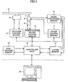
- FIG. 1 is a block diagram showing the composition of the optical disk drive in which the information recording method of the invention is embodied.
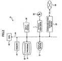
- FIG. 2 is a block diagram showing the electrical connection of the host computer in which the optical disk drive of FIG. 1 is provided.
- FIG. 3A, FIG. 3B and FIG. 3C are diagrams showing the composition of a multilayer optical disk which is placed in the optical disk drive.
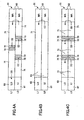
- FIG. 4A, FIG. 4B and FIG. 4C are diagrams for explaining the conventional method of recording of the multilayer optical disk, and the information recording method of the invention.
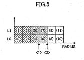
- FIG. 5 is a diagram for explaining the processing of padding.
- FIG. 6A and FIG. 6B are diagrams for explaining the relation between the radius position of the multilayer optical disk and the physical address, and the relation between the radius position of the multilayer optical disk and the logical address.
- FIG. 7 is a flowchart for explaining the processing performed by the optical disk drive of the preferred embodiment of the invention.
- FIG. 8 is a flowchart for explaining the processing performed by the host computer.
- FIG. 9 is a flowchart for explaining the processing performed by the optical disk drive of the preferred embodiment of the invention.
- FIG. 10 is a diagram showing an example of a dialog displayed on the host computer.
- FIG. 11 is a diagram showing an example of another dialog displayed on the host computer.
- FIG. 1 shows the outline composition of the optical disk drive 1 in which the information recording device of the invention is embodied.
- the optical disk D in which a plurality of record layers are laminated (called the “multilayer disk") is placed, and recording and reproduction of user information desired by the user to and from each record layer of the optical disk D is possible with the optical disk drive 1.
- the optical disk drive 1 comprises the spindle motor 2 which rotates the optical disk D, the optical pickup 3 which irradiates the laser light L to the optical disk D in order to perform the information recording and reproduction, and the pickup-moving motor 4 which moves the optical pickup 3 in the radius direction of the optical disk D.
- the optical pickup 3 is capable of focusing the laser light to the optical spot at each of the record layers, and thereby it is capable of accessing each record layer of the optical disk D.
- the spindle motor 2 is controlled by the rotation control module 5
- the pickup-moving motor 4 is controlled by the pickup-moving motor control module 6
- the optical pickup 3 is controlled by the pickup control module 7.
- the signal processing module 8 performs a predetermined signal processing of either the data signal read from the optical disk D by the optical pickup 3 or the data signal being recorded to the optical disk D by the optical pickup 3.
- the controller 9 is provided with CPU and controls the respective parts of the optical disk drive intensively.
- This controller 9 includes the high-speed memory including the registers etc. with a small storage capacity, and performs at high speed the buffer memory operation and digital signal processing which are the fixed digital processing.
- the data read from the optical disk D is stored in the buffer memory 11, and transmitted to the host computer 21 through the controller 9 and the interface 12.
- the data transmitted from the host computer 21 is stored in the buffer memory 11 through the interface 12 and the controller 9, and it is recorded in the optical disk D through the laser light from the optical pickup 3 and the signal processing module 8.
- the non-volatile memory 10 holds various kinds of the device setup information even if the power supply is off, and holds the data which must be retained for a long term period, including various control programs, various control parameters to various optical disks, etc.
- the controller 9 Based on the control program stored in the non-volatile memory 10, the controller 9 performs the processing performed by the optical disk drive 1 (which will be described later).
- the optical disk drive 1 communicates with the host computer 21 through the predetermined external interface.
- This interface may include ATA/ATAPI, SCSI, USB, IEEE1394, IEEE802, Serial ATA, etc. which can be used for the personal computers.
- Communication between the optical disk drive 1 and the host computer 21 is carried out by issuing the instruction data stream (command) from the host computer 21 to the optical disk drive 1, and the response to the command is sent from the optical disk drive 1 to the host computer 1.
- the recording operation mode can be changed to the reproducing operation mode, or the record layer (in the case of the multilayer disk), the location and the size, which is actually reproduced or recorded, etc. can be instructed.
- the specification of the recording location may be expressed by the logical address LBA as a single-dimension-address space for any type of the optical disk.
- the logical address is the address system used for specifying the recording position of the information by the optical disk drive 1 and the host computer side while the physical address is predetermined in the optical disk D.
- the focusing operation of the optical pickup 3 is required when operating it to the different record layers, and even if it is the linear address specification, the change timing of the record layer is explicit.
- FIG. 2 is a block diagram showing the electric connection of the host computer 21.
- the host computer 21 is a computer, such as PC (personal computer).
- the CPU 22 which performs various operations and controls respective parts of the host computer 21 intensively
- the memory 23 which includes various kinds of ROMs and RAMs are interconnected by the bus 24.
- the magnetic storage 25 such as the hard disk drive
- the input devices 26 such as the keyboard and the mouse
- the display device 27 the optical disk drive 1
- the communication control device 29 which communicates with the network 28.
- the recording medium 30 may be any of various media, including the optical disks, such as CD, DVD, the magneto-optic disk, and the flexible disk, which can be read using the optical disk drive 1 and other drive devices.
- the information recording system of the present invention can be carried out with the host computer 21 provided with the optical disk drive 1.
- the host computer 21 reads the control program 31 in which the information recording program of the invention is embodied, from the recording medium 30 in which the recording medium of the invention is embodied, and installs it in the magnetic storage 25.
- These programs may be downloaded through the network 28, such as the Internet, and installed in the magnetic storage 25. By this installation, the host computer 21 is set in the state which can perform the predetermined processing. In addition, the control program 31 may be operated on the predetermined OS.
- FIG. 3A through FIG. 3C are diagrams showing the fundamental composition of the multilayer disk 51 which is the multilayer recording medium in which information is recorded and reproduced by the optical disk drive 1.
- the multilayer disk 51 is the disk-like plate in which two or more record layers 52 are laminated, and the protection layers 53 are formed between the information recording/reproducing surfaces and the record layers 52.
- the optical disk in which information can be recorded only on one surface of the disk is used, and the cover layer 54 is formed on the other surface of the disk opposite to the recording/reproducing surface.
- the record layer 52 may be the write-once type or the rewritable type, in order to carry the recording function, it may be further divided into two or more fine record layers from which the physical characteristic differs.
- the record layer 52 of the near position will be passed from the recording head.
- the recording characteristics and reproducing characteristics for every record layer 52 are varied in many cases.
- FIG. 3C shows the relation between the radius position of the multilayer disk 51 and the physical address.
- the physical address is continuously assigned within the single record layer 52 (layers 0-2 indicate the record layer 52, respectively). There are also various methods of assigning the physical addresses.
- the address continues only in the innermost or the outermost circumference.
- the composition in which the address continues on the outer circumference is called OTP (opposite track path).
- PTP parallel track path
- the lead-in (LI) groove 61 is recorded at the beginning of the record layer 52 (layer0) which is recorded first.
- the middle area (MA) 62 is recorded at the last of each of the record layers 52 (layer0 and layer1). Exceptionally, the lead-out (LO) 63 is recorded at the last of the last record layer 52 (layer2).
- the intermediate area between the lead-in groove 61 and the middle area 62 (or the lead-out 63) is the data area 64 in which the user data is recorded.
- the multilayer disk 51 having the two-layer structure with the two record layers 52 will be explained as an example.
- the general recording method for the multilayer disk 51 there are two methods (a) and (b).
- the OTP recording is performed in order of layer0 (L0) and layer1 (L1), and the additional recording is performed similar to the optical disk D of the single layer.
- the recording is performed consecutively to all the record layers 52.
- the first recording (1) is performed so that the lead-in groove 61, the user data 71, and the closure 72 are recorded.
- the second and subsequent recordings (2) and (3) are performed so that the intro 73, the user data 71, and the closure 72 are recorded, and the middle area 62 is recorded at each of the tail end of layer0 and the head end of layer1, respectively.
- the last recording (4) is performed so that the lead-out 63 is recorded at the tail end of layer1 in the last recording (4).
- the recording is performed consecutively to all the record layers 52 (layer0 and layer 1), and neither the intro 73 nor the closure 72 is recorded in the data area 64.
- FIG. 4C is a diagram for explaining the information recording method of the preferred embodiment of the invention for the multilayer disk 51, which is performed by the optical disk drive 1.
- the recording is performed when the amount of the information being recorded to the multilayer disk 51 does not exceed the storage capacity of all the record layers 52 of the multilayer disk 51.
- the non-recorded regions remain in any of the record layers 52 of the multilayer disk 51 at the end of the recording of all the data to be recorded to the medium, and the regions other than the data-recorded areas of the medium are set in the recording-end state before the recording of all the data is finished.
- the data being recorded to the disk is divided into data blocks by the number of the record layers 52 (in the example of FIG. 4C, the number of record layers is equal to 2).
- the data blocks are sequentially recorded to the respective record layers 52 of the multiplayer disk 51 so that the recording areas of the record layers 52 where the data blocks are recorded are overlapped each other with respect to the thickness direction of the multiplayer disk 51.
- the recording is performed so that most of the recording areas of the record layers 52 where the data blocks are recorded have no regions which are not overlapped each other with respect to the thickness direction of the multilayer disk 51. Practically; however, due to the relation of the minimum recording unit of the multilayer disk 51, the regions which are not overlapped may partially remain in the recording areas of the record layers 52 where the data blocks are recorded.
- the information recording method as shown in FIG. 4C is performed.
- the lead-in groove 61 which indicates the start of recording of the multilayer disk 51 and the start of recording of the first layer
- the user data 71 which indicates the end of recording of the first layer
- the closure 72 which indicates the end of recording of the first layer (which closure 72 also becomes the information which indicates the interruption (session closing) of recording with the additional recording being permitted later) are recorded from the head end of layer0 (the first layer).
- the data (which corresponds to the intro 73 and will be called the start area 74 in the present specification) which indicates the start of recording of the second layer, the user data 71, and the lead-out 63 which indicates the end of recording of the second layer (which lead-out 63 also becomes the information which indicates the end of recording of the multilayer disk 51; this information being recorded in this stage) are recorded.
- the lead-in groove 61 which indicates the start of recording of the first layer, the user data 71, and the closure 72 which indicates the end of recording of the first layer are recorded immediately after the closure 72 in the previous recording of the first layer (layer0).
- the start area 74 which indicates the start of recording of the second layer, the user data 71, and the data which indicates the end of recording of the second layer (which data corresponds to the closure 72 and will be called the end area 75 in the present specification) are recorded.
- the lead-in groove 61 which indicates the start of recording of the first layer (layer0), the user data 71, and the middle area 62 which indicates the end of recording of the first layer (which middle area 62 also becomes the information which indicates the completion (disk closing) of the recording with the additional recording being inhibited) are recorded.
- the middle area 62 which indicates the start of recording of the second layer, the user data 71, and the end area 75 which indicates the end of recording of the second layer are recorded.
- the above-described information recording method does not record one of the record layers 52 consecutively for all the areas.
- the data recording is performed consecutively from the inner circumference side of the multilayer disk 51 one by one, and such data recording is repeatedly performed for all of the two or more record layers 52.
- the closure 72 or the end area 75 (or the lead-in groove 63) is recorded to all the record layers 52, which indicates explicitly that the interruption of the data recording is performed there.
- the middle area 62 is recorded to all the record layers 52 in the same manner, which will inhibit the data recording from being further performed later.
- FIG. 6A shows the relation between the radius position (radius) of the multilayer disk 51 and the physical address (PSN) in the case of performing the above-mentioned information recording method.
- the physical address increases from the inner circumference side of the multilayer disk 51 to the outer circumference side at a fixed rate, and the data recording to the second record layer 52 overlapping just above the first recording layer 52 is restricted, so that the data recording is uniformly performed to all the record layers 52.
- the total amount of the data being recorded to the optical disk once is known at the start of the data recording, and the data of the total amount is divided into the data blocks by the number of the record layers 52. Then the amount of the data for one record layer 52 is calculated.
- the last address of the first record layer is specified beforehand, and the data recording to the subsequent addresses after the last address of the first recording layer is inhibited. Hence, the subsequent address of the second layer can be automatically decided. Therefore, even if the data recording to the two or more record layers 52 is performed, the logical address can be properly assigned without causing a deviation in the logical address.
- the proper physical address up to L1 is assigned.
- the total amount of records of the data being recorded to the optical disk by the next recording is known and the radius position of the last record position of the first record layer 52 is M2.
- the proper physical address up to L2 is assigned.
- the data recording to each of the record layers 52 is not necessarily distributed equally to each record layer 52.
- the padding is performed using the predetermined value (for example, zero) so that the predetermined data is compensated for the non-match region.
- the data recording is carried out so that the regions of the respective record layers 52 where the data recording is performed are overlapped completely.
- FIG. 5 is a diagram for explaining the processing of padding.
- the two files (files 1 and 2) are recorded by the first recording operation (they are recorded up to the position of ⁇ 1>).
- the file 1 corresponds to the blocks of (0) - (2)
- the file 2 corresponds to the blocks of (3) - (4)
- the block of (5) is compensated for by the padding.
- the second recording operation is performed up to the position of ⁇ 2>, and only the file 3, corresponding to the block of (6), is recorded.
- the block of (7) is compensated for by the padding.
- FIG. 7 is a flowchart for explaining the processing which is performed by the optical disk drive 1.
- the first recording unit in the claims is realized by the processing of FIG. 7.
- the write command (WRITE) is used to supply the instructions for the data recording to the optical disk drive 1, and there are some methods for this purpose.
- the three procedures 81, 82 and 83 there are provided the three procedures 81, 82 and 83.
- the common processing for the three procedures is the steps S1 and S2.
- the processing of FIG. 7 is started when the multilayer disk 51 is loaded into the optical disk drive 1.
- the controller 9 checks the kind of the multilayer disk 51, and the number N of the record layers 52 (step S1).
- the controller 9 sets the optical disk drive 1 in the state of awaiting receiving of a command from the host computer 21 (step S2).
- control is branched to one of the three procedures according to the received command and the processing is completed. Then, the control is returned back to the waiting loop for the command from the host computer 21 (step S2) again.
- the first procedure is the processing which is performed when the Write (HOST) command is received (the procedure 81).
- the logical-address range which corresponds to the number of the record layers 52 is determined, and the write command is issued respectively.
- the data recording is performed by the optical disk drive 1 except the error checking, and the data is recorded only to the specified addresses (step S11).
- the logical addresses where the data recording is performed in the multilayer disk 51 of the three record layers 52, when the number of recording sectors of the single record layer is 230540h in the OTP recording and the first 16 sectors of the disk are recorded are as indicated in the step S11 of FIG. 7. Namely, by performing the above-mentioned information recording method from the head end or tail end of each record layer 52, the first 16 sectors of the first record layer 52, the last 16 sectors of the second record layer 52, the first 16 sectors of the third record layer 52, etc. are recorded in this order.
- FIG. 8 is a flowchart for explaining the processing which is performed by the host computer 21 when the data recording procedure 81 is taken.
- the CPU 22 Based on the program 31 according to the program of the present invention, the CPU 22 performs the processing of FIG. 8.
- the first instruction unit in the claims is realized by the processing of FIG. 8.
- the CPU 22 looks into the state of the multilayer disk 51, checks the number N of the record layers 52, and resets the count value n of a predetermined counter to 0 (step S41).
- the CPU 22 checks the last address of each record layer 52 where the data recording is previously completed (thereby, the address where the starting of the data recording is possible is checked) (step S42).
- the direction of the data recording in the even-numbered record layer 52 is reverse to the direction of the data recording in the odd-numbered record layer 52, and the address immediately before the position where the data recording is previously completed is checked at this step.
- the CPU 22 prepares the data which is to be recorded, and decides the total amount of the recording data (step S43).
- the amount of the recording data equally divided for each record layer 52 (which is referred to as "s") is calculated from the decided total amount of the recording data and the number of record layers 52.
- this recording amount "s" is calculated by dividing the total amount of the recording data by the number of the record layers 52 (step S43).
- the data recording is performed sequentially from the first record layer 52.
- the start position of the data recording follows from the last address where the previous data recording is completed by the number s
- the start position of the data recording precedes from the last address where the previous data recording is completed by the number s, respectively (steps S45-S47).
- the CPU 22 issues the Write (HOST) command to the optical disk drive 1 (step S48), and waits for the end of the data recording by the optical disk drive 1 (step S49). Thereby, the above-mentioned processing (procedure 81) is performed by the optical disk drive 1 when the Write (HOST) command is received.
- the CPU 22 increments the count value n of the predetermined counter (step S48).
- the second procedure is the processing which is performed when the Write (N-TIMES) command is received (procedure 82).
- the command reception is performed after the predetermined count value n is reset to 0.
- the data recording can be performed if the command is received within the number N of record layers, the address in the command is changed to the applicable address in the record layer 52 (step S22). However, the address in the command remains unchanged for the first time.
- the recording data is received from the host computer 21 (step S23), and the data is actually recorded to the optical disk (step S24).
- step S25 the count value n is incremented (step S25), and the optical disk drive 1 waits for reception of the following command.
- the third procedure is the processing which is performed when the Write (MULTI BLOCK) command is received (procedure 83).
- the write command is issued once in the range of the single record layer 52, and the recording data is transmitted by the data transfer for the amount of the recording data for all the record layers 52.
- the command is received and all the recording data is received (step S31).
- the recording of the received data to the applicable address of the optical disk is performed from the starting position (step S32).
- step S33 the count value n is incremented (step S33), and the record layer 52 is changed to the next one.
- step S34 When the count value n is below the number N of record layers (or when the result at the step S34 is affirmative), the address is changed to the address in the applicable record layer 52 (step S35), and the control is returned to the step S32, and the data recording in the range is performed again.
- This procedure is characterized in that the optical disk drive 1 is controlled to operate so that it may record the user data to all the record layers 52 per one recording unit.
- step S3 it is detected whether a predetermined write error occurs in the middle of the data recording.
- step S4 a predetermined error processing is performed (step S4).
- step S4 it is in the middle of record of the data, and after making each record layer 52 record end by the predetermined data altogether even if it is the middle when it becomes the error, it is good to make it make record operation complete.
- the second and the third processing can do the logical address to specify simply similarly to the optical disk of the single record layer, if they are not the record formats to which structure is fixed to some extent in order to record also on the different place from the logical-address range specified by the record command, they will tend to cause the confusion.
- steps S1-S4 is the same as in the processing of FIG. 7, and a description thereof will be omitted.
- This command is temporarily set to the reserve layer.
- the optical disk drive 1 will check that it is the non-recorded multilayer disk 51 (step S51), will determine the amount of the recording data per layer from the total amount of records of the data specified by the command, and the record number of layers N, will determine the logical-address range of each record layer 52, and will record it on the lead in groove 61 of the multilayer disk 51 etc. (step S52).
- the address of the record layer 52 after the second layer can be automatically decided by forbidding record to the address after it.
- the address which does not have conflict by this though written in two or more record layers 52 can be assigned.
- procedure 92 After the end of data recording by processing of FIG. 7, in case the procedure 92 performs the interruption (session closing) of the record to the multilayer disk 51, it is processing which records each non-recorded region by the predetermined data to N record layers 52 automatically.
- reception of the Close Session command decides the logical address recorded on the outermost circumference in each record layer 52 (step S61).
- step S62 It is confirmed whether it is reproducible in reproduction mode to each logical address.
- step S63 Since it is necessary to make the non-recorded area record settled so that step may be kept with the sector most located in the outermost circumference as compared with other record layers 52 when reproduction is unstable, it judges whether this is possible (step S63). If this is impossible (N of step S62), it considers as the error (step S4).
- the predetermined data will be recorded, if this is possible (Y of step S62) and there is the non-recorded area by the inner side of the outermost circumference address of each record layer 52 (step S64), which will realize the fourth recording unit in the claims. Thereby, the completion of each fragment is guaranteed.
- the logical ad logical address which arranges the closure 72 of each record layer 52 and the start area 74 is determined (step S65), and record of the intro 73 (or the lead-in groove 61) of each record layer 52, the closure 72 (it becomes the information which indicates the next additional recording or that record is interrupted temporarily so that it may be possible (session closing)), and the start area 74 is performed (step S66), which will realizes the second recording unit in the claims.
- the procedure 93 completes the data recording to the multilayer disk 51 (disk closing), which indicates that the procedure which records each non-recorded region by writing the predetermined data to the N record layers 52 automatically. This is almost the same procedure as the session closing.
- reception of the Close Disk command decides the logical address recorded on the outermost circumference in each record layer 52 (step S71). It is confirmed whether it is reproducible in reproduction mode to each logical address (step S72).
- step S73 Since it is necessary to make the non-recorded area record settled so that step may be kept with the sector most located in the outermost circumference as compared with other record layers 52 when reproduction is unstable, it judges whether this is possible (step S73). If this is impossible (N of step S73), it considers as the error (step S4).
- the predetermined information will be recorded, if this is possible (N of step S73) and there is the non-recorded area by the inner side of the outermost circumference address of each record layer 52 (step S74), which will achieves the fourth recording unit in the claims. Thus, the completion of each fragment is guaranteed.
- step S75 The logical address which arranges the middle area 62 of each record layer 52 is determined (step S75), and record of the intro 73 and the area 75 (it becomes the information which shows the next additional recording or that record is completed so that it may be impossible (disk closing)), and the middle area 62 is performed (step S76), which will realize the third recording unit in the claims.
- the middle area 62 becomes the region which the lead in groove 61 and lead-out 63 do in address, and divides between the record layers 52. Data recording to the perimeter is not made from the middle area 62. Since it can be made by this the completed same recording medium as the multilayer disk only for the multilayer disk 51 reproduction, improvement in reproduction compatibility is expectable.
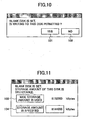
- FIG. 9 shows an example of the dialog displayed on the host computer 21.
- the user is allowed, at the time of the start of the recording to the multilayer disk 51, to selectively determine whether the additional recording is used, by displaying this dialog.
- the button 103 When the button 103 is chosen, the maximum capacity of the multilayer disk 51 is used, and when the button 104 is chosen, the user specifies the desired storage capacity.
- the multilayer recording medium treated by the present invention may be the magneto-optic disk etc.
Landscapes
- Engineering & Computer Science (AREA)
- Signal Processing (AREA)
- Multimedia (AREA)
- Optical Recording Or Reproduction (AREA)
- Signal Processing For Digital Recording And Reproducing (AREA)
- Indexing, Searching, Synchronizing, And The Amount Of Synchronization Travel Of Record Carriers (AREA)
- Management Or Editing Of Information On Record Carriers (AREA)
Applications Claiming Priority (2)
| Application Number | Priority Date | Filing Date | Title |
|---|---|---|---|
| JP2003328754A JP3710799B2 (ja) | 2003-09-19 | 2003-09-19 | 情報記録方法、情報記録装置及び情報記録システム |
| JP2003328754 | 2003-09-19 |
Publications (3)
| Publication Number | Publication Date |
|---|---|
| EP1517312A2 true EP1517312A2 (de) | 2005-03-23 |
| EP1517312A3 EP1517312A3 (de) | 2007-09-26 |
| EP1517312B1 EP1517312B1 (de) | 2009-10-28 |
Family
ID=34191404
Family Applications (1)
| Application Number | Title | Priority Date | Filing Date |
|---|---|---|---|
| EP04255706A Expired - Lifetime EP1517312B1 (de) | 2003-09-19 | 2004-09-20 | Verfahren und Vorrichtung zur Informationsaufzeichnung in optischen Mehrfachschichten |
Country Status (5)
| Country | Link |
|---|---|
| US (1) | US7339868B2 (de) |
| EP (1) | EP1517312B1 (de) |
| JP (1) | JP3710799B2 (de) |
| DE (1) | DE602004023801D1 (de) |
| TW (1) | TWI301611B (de) |
Cited By (4)
| Publication number | Priority date | Publication date | Assignee | Title |
|---|---|---|---|---|
| EP1708179A4 (de) * | 2004-01-20 | 2010-05-19 | Pioneer Corp | Informationsaufzeichnungseinrichtung und informationsaufzeichnungsverfahren und computerprogramm |
| EP1703506A4 (de) * | 2004-01-06 | 2011-11-09 | Pioneer Corp | Informationsaufzeichnungseinrichtung und verfahren |
| US8397021B2 (en) | 2005-12-06 | 2013-03-12 | Konikklijke Philips Electronics N.V. | Formatting multi-layer storage media |
| US9076460B2 (en) | 2003-10-06 | 2015-07-07 | Koninklijke Philips N.V. | Multiple layer optical disc, and device for writing such disc |
Families Citing this family (14)
| Publication number | Priority date | Publication date | Assignee | Title |
|---|---|---|---|---|
| JP2004310972A (ja) * | 2003-03-25 | 2004-11-04 | Ricoh Co Ltd | 情報処理装置、情報記録装置、情報処理システム、情報記録方法、情報記録用プログラム及び記憶媒体 |
| JP3594243B1 (ja) * | 2003-03-25 | 2004-11-24 | 株式会社リコー | 光情報記録方法、光情報記録装置、情報処理装置、光情報記録媒体 |
| JP3734816B2 (ja) * | 2003-03-25 | 2006-01-11 | 株式会社リコー | 光情報記録装置、光情報記録媒体、光情報記録方法、プログラム、及び記憶媒体 |
| JP4406404B2 (ja) | 2004-02-04 | 2010-01-27 | パイオニア株式会社 | 情報記録媒体、情報記録装置及び方法、コンピュータプログラム |
| EP1742206A4 (de) * | 2004-04-26 | 2009-02-25 | Ricoh Kk | Informationsaufzeichnungseinrichtung, informationsaufzeichnungssystem, programm und aufzeichnungsmedium |
| JP4353536B2 (ja) * | 2004-05-17 | 2009-10-28 | パイオニア株式会社 | 情報記録装置及び方法、情報再生装置及び方法、並びにコンピュータプログラム |
| JP4213128B2 (ja) * | 2005-02-25 | 2009-01-21 | 株式会社リコー | 記録方法、プログラム及び記録媒体、並びに情報記録装置 |
| US20090231986A1 (en) * | 2005-04-27 | 2009-09-17 | Pioneer Corporation | Information recording apparatus and method, information reproducing apparatus and method, information recording medium, and computer program |
| US20090303860A1 (en) * | 2005-05-31 | 2009-12-10 | Pioneer Corporation | Recording Process Status Deciding Apparatus and Recording Process Status Deciding Method |
| JP2007128578A (ja) * | 2005-11-01 | 2007-05-24 | Ricoh Co Ltd | 情報記録装置 |
| TW200721137A (en) | 2005-11-17 | 2007-06-01 | Ind Tech Res Inst | Data structure of the recording medium and method for reading the recording medium data |
| EP1903574A3 (de) * | 2006-09-20 | 2008-11-26 | Panasonic Corporation | Datenverarbeitungsvorrichtung, Aufzeichnungsgerät und mehrschichtige Speicherplatte |
| JP5756673B2 (ja) * | 2011-04-27 | 2015-07-29 | 日立コンシューマエレクトロニクス株式会社 | 記録再生装置 |
| JP6007613B2 (ja) * | 2012-06-22 | 2016-10-12 | ソニー株式会社 | 記録管理装置、記録管理方法、プログラム |
Family Cites Families (19)
| Publication number | Priority date | Publication date | Assignee | Title |
|---|---|---|---|---|
| US5729525A (en) | 1995-06-21 | 1998-03-17 | Matsushita Electric Industrial Co., Ltd. | Two-layer optical disk |
| JP3756574B2 (ja) | 1995-06-21 | 2006-03-15 | 松下電器産業株式会社 | 2層光ディスク |
| JP2000503446A (ja) | 1995-10-19 | 2000-03-21 | 松下電器産業株式会社 | 情報記憶媒体および情報再生方法および情報再生装置 |
| JP3435264B2 (ja) | 1995-10-24 | 2003-08-11 | 株式会社リコー | 画像形成装置 |
| JP3841468B2 (ja) | 1996-03-22 | 2006-11-01 | 富士通テン株式会社 | 多層式ディスク及び多層式ディスクの記録装置 |
| JP3707137B2 (ja) | 1996-07-04 | 2005-10-19 | ソニー株式会社 | 記録媒体、再生装置 |
| JPH1131357A (ja) | 1997-07-08 | 1999-02-02 | Pioneer Electron Corp | 情報データの記録方法 |
| EP2261920A3 (de) * | 1998-02-23 | 2011-03-09 | Kabushiki Kaisha Toshiba | Informationsaufzeichnungsmedium, Informationswiedergabeverfahren und -vorrichtung, und Informationsaufzeichnungsverfahren |
| JP2000163865A (ja) | 1998-11-26 | 2000-06-16 | Ricoh Co Ltd | 情報転送装置 |
| JP2000270299A (ja) | 1999-03-16 | 2000-09-29 | Ricoh Co Ltd | 画像記録再生装置 |
| JP2001126255A (ja) | 1999-10-22 | 2001-05-11 | Sony Corp | 光記録方法及び光記録装置 |
| JP2001216647A (ja) * | 1999-11-22 | 2001-08-10 | Sanyo Electric Co Ltd | 制御装置 |
| JP2001338458A (ja) | 2000-05-26 | 2001-12-07 | Ricoh Co Ltd | 情報記録装置、情報記録システム及び情報記憶媒体 |
| JP4185659B2 (ja) | 2000-11-06 | 2008-11-26 | パイオニア株式会社 | 光記録媒体、情報記録装置および情報再生装置 |
| JP3947428B2 (ja) | 2001-09-10 | 2007-07-18 | 株式会社リコー | 情報記録再生装置及びそのシステム |
| JP2003173285A (ja) | 2001-09-26 | 2003-06-20 | Ricoh Co Ltd | 情報記録方法及び情報記録再生装置 |
| US6801494B2 (en) | 2001-10-31 | 2004-10-05 | Koninklijke Philips Electronics N.V. | Multiple sections for dual-layer optical recording medium |
| KR100975299B1 (ko) | 2002-06-10 | 2010-08-12 | 코닌클리케 필립스 일렉트로닉스 엔.브이. | 다중층 광 디스크 기록방법 및 장치 |
| JP4027726B2 (ja) | 2002-06-17 | 2007-12-26 | 株式会社リコー | 情報記録再生装置と情報記録再生方法とプログラムと記録媒体及び情報記録再生システム |
-
2003
- 2003-09-19 JP JP2003328754A patent/JP3710799B2/ja not_active Expired - Fee Related
-
2004
- 2004-09-16 TW TW093127977A patent/TWI301611B/zh not_active IP Right Cessation
- 2004-09-17 US US10/942,807 patent/US7339868B2/en not_active Expired - Fee Related
- 2004-09-20 DE DE602004023801T patent/DE602004023801D1/de not_active Expired - Lifetime
- 2004-09-20 EP EP04255706A patent/EP1517312B1/de not_active Expired - Lifetime
Cited By (5)
| Publication number | Priority date | Publication date | Assignee | Title |
|---|---|---|---|---|
| US9076460B2 (en) | 2003-10-06 | 2015-07-07 | Koninklijke Philips N.V. | Multiple layer optical disc, and device for writing such disc |
| US9489134B2 (en) | 2003-10-06 | 2016-11-08 | Koninklijke Philips N.V. | Multiple layer optical disc, and device for writing such disc |
| EP1703506A4 (de) * | 2004-01-06 | 2011-11-09 | Pioneer Corp | Informationsaufzeichnungseinrichtung und verfahren |
| EP1708179A4 (de) * | 2004-01-20 | 2010-05-19 | Pioneer Corp | Informationsaufzeichnungseinrichtung und informationsaufzeichnungsverfahren und computerprogramm |
| US8397021B2 (en) | 2005-12-06 | 2013-03-12 | Konikklijke Philips Electronics N.V. | Formatting multi-layer storage media |
Also Published As
| Publication number | Publication date |
|---|---|
| JP3710799B2 (ja) | 2005-10-26 |
| TWI301611B (en) | 2008-10-01 |
| EP1517312B1 (de) | 2009-10-28 |
| US20050063290A1 (en) | 2005-03-24 |
| DE602004023801D1 (de) | 2009-12-10 |
| JP2005093031A (ja) | 2005-04-07 |
| TW200512729A (en) | 2005-04-01 |
| US7339868B2 (en) | 2008-03-04 |
| EP1517312A3 (de) | 2007-09-26 |
Similar Documents
| Publication | Publication Date | Title |
|---|---|---|
| EP1517312B1 (de) | Verfahren und Vorrichtung zur Informationsaufzeichnung in optischen Mehrfachschichten | |
| US8000201B2 (en) | Information recording system with information recording and reproducing apparatus having a data recorder | |
| CN100550141C (zh) | 信息记录方法、信息记录装置 | |
| US7385897B2 (en) | Information recording device, information recording method, information recording program, and recording medium | |
| JP3594243B1 (ja) | 光情報記録方法、光情報記録装置、情報処理装置、光情報記録媒体 | |
| TW200425078A (en) | Data recording method, data recording device, program, and computer-readable data memory medium | |
| JP4083651B2 (ja) | 情報記録方法及び情報記録装置 | |
| US7324422B2 (en) | Information storage method that assures compatibility of writable medium with read only medium | |
| JP3908967B2 (ja) | 情報記録装置 | |
| JP4375677B2 (ja) | 情報記録媒体、情報記録装置及び方法、並びにコンピュータプログラム | |
| JP2008542971A (ja) | 多層光ディスクに情報を記録するための方法及び装置 | |
| JP3825437B2 (ja) | アドレス変換プログラム、記録プログラム、記憶媒体、及び情報処理装置 | |
| JP4728750B2 (ja) | 情報記録装置及び情報記録方法 | |
| JP4287413B2 (ja) | 情報記録方法、情報記録装置、情報記録システム、プログラム及び記憶媒体 | |
| US20050276187A1 (en) | Method of allocating areas in optical disc, data recording and/or reproducing apparatus adopting the same, and optical disc therefor | |
| EP1806741A1 (de) | Informationsaufzeichnungsverfahren, bei dem kompatibilität mit nur wiedergebbaren medien aufrechterhalten wird | |
| JP4083780B2 (ja) | 情報記録システム | |
| CN100421169C (zh) | 信息记录装置、信息记录方法 | |
| JP2006313642A (ja) | 情報記録媒体 | |
| JP2004335033A (ja) | 追記型記録媒体、記録方法、記録装置 |
Legal Events
| Date | Code | Title | Description |
|---|---|---|---|
| PUAI | Public reference made under article 153(3) epc to a published international application that has entered the european phase |
Free format text: ORIGINAL CODE: 0009012 |
|
| 17P | Request for examination filed |
Effective date: 20040929 |
|
| AK | Designated contracting states |
Kind code of ref document: A2 Designated state(s): AT BE BG CH CY CZ DE DK EE ES FI FR GB GR HU IE IT LI LU MC NL PL PT RO SE SI SK TR |
|
| AX | Request for extension of the european patent |
Extension state: AL HR LT LV MK |
|
| PUAL | Search report despatched |
Free format text: ORIGINAL CODE: 0009013 |
|
| AK | Designated contracting states |
Kind code of ref document: A3 Designated state(s): AT BE BG CH CY CZ DE DK EE ES FI FR GB GR HU IE IT LI LU MC NL PL PT RO SE SI SK TR |
|
| AX | Request for extension of the european patent |
Extension state: AL HR LT LV MK |
|
| 17Q | First examination report despatched |
Effective date: 20080313 |
|
| AKX | Designation fees paid |
Designated state(s): DE ES FR GB IT NL |
|
| GRAP | Despatch of communication of intention to grant a patent |
Free format text: ORIGINAL CODE: EPIDOSNIGR1 |
|
| GRAS | Grant fee paid |
Free format text: ORIGINAL CODE: EPIDOSNIGR3 |
|
| GRAA | (expected) grant |
Free format text: ORIGINAL CODE: 0009210 |
|
| AK | Designated contracting states |
Kind code of ref document: B1 Designated state(s): DE ES FR GB IT NL |
|
| REG | Reference to a national code |
Ref country code: GB Ref legal event code: FG4D |
|
| REF | Corresponds to: |
Ref document number: 602004023801 Country of ref document: DE Date of ref document: 20091210 Kind code of ref document: P |
|
| NLV1 | Nl: lapsed or annulled due to failure to fulfill the requirements of art. 29p and 29m of the patents act | ||
| PG25 | Lapsed in a contracting state [announced via postgrant information from national office to epo] |
Ref country code: ES Free format text: LAPSE BECAUSE OF FAILURE TO SUBMIT A TRANSLATION OF THE DESCRIPTION OR TO PAY THE FEE WITHIN THE PRESCRIBED TIME-LIMIT Effective date: 20100208 |
|
| PLBE | No opposition filed within time limit |
Free format text: ORIGINAL CODE: 0009261 |
|
| STAA | Information on the status of an ep patent application or granted ep patent |
Free format text: STATUS: NO OPPOSITION FILED WITHIN TIME LIMIT |
|
| 26N | No opposition filed |
Effective date: 20100729 |
|
| PG25 | Lapsed in a contracting state [announced via postgrant information from national office to epo] |
Ref country code: IT Free format text: LAPSE BECAUSE OF FAILURE TO SUBMIT A TRANSLATION OF THE DESCRIPTION OR TO PAY THE FEE WITHIN THE PRESCRIBED TIME-LIMIT Effective date: 20091028 |
|
| PG25 | Lapsed in a contracting state [announced via postgrant information from national office to epo] |
Ref country code: NL Free format text: LAPSE BECAUSE OF FAILURE TO SUBMIT A TRANSLATION OF THE DESCRIPTION OR TO PAY THE FEE WITHIN THE PRESCRIBED TIME-LIMIT Effective date: 20091028 |
|
| REG | Reference to a national code |
Ref country code: FR Ref legal event code: PLFP Year of fee payment: 13 |
|
| REG | Reference to a national code |
Ref country code: FR Ref legal event code: PLFP Year of fee payment: 14 |
|
| REG | Reference to a national code |
Ref country code: FR Ref legal event code: PLFP Year of fee payment: 15 |
|
| PGFP | Annual fee paid to national office [announced via postgrant information from national office to epo] |
Ref country code: FR Payment date: 20190925 Year of fee payment: 16 |
|
| PGFP | Annual fee paid to national office [announced via postgrant information from national office to epo] |
Ref country code: GB Payment date: 20190920 Year of fee payment: 16 |
|
| PGFP | Annual fee paid to national office [announced via postgrant information from national office to epo] |
Ref country code: DE Payment date: 20200909 Year of fee payment: 17 |
|
| GBPC | Gb: european patent ceased through non-payment of renewal fee |
Effective date: 20200920 |
|
| PG25 | Lapsed in a contracting state [announced via postgrant information from national office to epo] |
Ref country code: FR Free format text: LAPSE BECAUSE OF NON-PAYMENT OF DUE FEES Effective date: 20200930 |
|
| PG25 | Lapsed in a contracting state [announced via postgrant information from national office to epo] |
Ref country code: GB Free format text: LAPSE BECAUSE OF NON-PAYMENT OF DUE FEES Effective date: 20200920 |
|
| REG | Reference to a national code |
Ref country code: DE Ref legal event code: R119 Ref document number: 602004023801 Country of ref document: DE |
|
| PG25 | Lapsed in a contracting state [announced via postgrant information from national office to epo] |
Ref country code: DE Free format text: LAPSE BECAUSE OF NON-PAYMENT OF DUE FEES Effective date: 20220401 |