EP1516652B1 - Schneegleitbrett, beispielsweise Snowboard - Google Patents
Schneegleitbrett, beispielsweise Snowboard Download PDFInfo
- Publication number
- EP1516652B1 EP1516652B1 EP04020232A EP04020232A EP1516652B1 EP 1516652 B1 EP1516652 B1 EP 1516652B1 EP 04020232 A EP04020232 A EP 04020232A EP 04020232 A EP04020232 A EP 04020232A EP 1516652 B1 EP1516652 B1 EP 1516652B1
- Authority
- EP
- European Patent Office
- Prior art keywords
- insert
- board body
- glide
- recess
- snow gliding
- Prior art date
- Legal status (The legal status is an assumption and is not a legal conclusion. Google has not performed a legal analysis and makes no representation as to the accuracy of the status listed.)
- Expired - Lifetime
Links
- 238000004519 manufacturing process Methods 0.000 claims abstract description 3
- 238000000034 method Methods 0.000 claims abstract description 3
- 239000000463 material Substances 0.000 claims description 7
- 229920001169 thermoplastic Polymers 0.000 claims description 4
- 239000011347 resin Substances 0.000 claims 1
- 229920005989 resin Polymers 0.000 claims 1
- 238000004381 surface treatment Methods 0.000 claims 1
- 239000004416 thermosoftening plastic Substances 0.000 claims 1
- 239000012815 thermoplastic material Substances 0.000 abstract description 3
- 238000010438 heat treatment Methods 0.000 description 2
- 229920000642 polymer Polymers 0.000 description 2
- 230000015572 biosynthetic process Effects 0.000 description 1
- 230000001419 dependent effect Effects 0.000 description 1
- 238000011161 development Methods 0.000 description 1
- 230000018109 developmental process Effects 0.000 description 1
- 239000000428 dust Substances 0.000 description 1
- 238000012986 modification Methods 0.000 description 1
- 230000004048 modification Effects 0.000 description 1
- 239000004033 plastic Substances 0.000 description 1
- 239000000843 powder Substances 0.000 description 1
- 239000007921 spray Substances 0.000 description 1
Images

Classifications
-
- A—HUMAN NECESSITIES
- A63—SPORTS; GAMES; AMUSEMENTS
- A63C—SKATES; SKIS; ROLLER SKATES; DESIGN OR LAYOUT OF COURTS, RINKS OR THE LIKE
- A63C5/00—Skis or snowboards
- A63C5/04—Structure of the surface thereof
- A63C5/044—Structure of the surface thereof of the running sole
-
- A—HUMAN NECESSITIES
- A63—SPORTS; GAMES; AMUSEMENTS
- A63C—SKATES; SKIS; ROLLER SKATES; DESIGN OR LAYOUT OF COURTS, RINKS OR THE LIKE
- A63C5/00—Skis or snowboards
- A63C5/03—Mono skis; Snowboards
Definitions
- the invention relates to a snowboard, for example, snowboard according to the preamble of claim 1 and to a method according to the preamble of claim 13.
- the object of the invention is to show a snowboard with improved handling.
- a snow sliding board is designed according to claim 1.
- a method for producing the snow gliding board is the subject of patent claim 13.
- thermoplastic material for the at least one insert, it is possible to use this insert initially in a recess which does not have the recess at the bottom of the insert, i. to mount the non-curved shape in the gliding board body, then to mechanically machine the underside of the gliding board body and the underside of the insert, i. to grind, so as not only for the bottom of the sliding board body, but also for the bottom of the insert to achieve a smooth, optimal driving characteristics ensuring surface. Only in a subsequent operation is then the use under heating so permanently deformed that he then has the open to the bottom and the end of the sliding board body recess.
- FR-A-2804612 shows a snow sliding board with a trough which is open at the top.
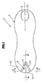
- 1 is a snow sliding board in the form of a snowboard.
- the snowboard body 2 has the usual structure and the usual shape, and in particular with a rear, scoop-like upwardly curved end or blade area 2.1 and a front, also scoop-like upwardly curved end or blade area 2.2.
- an insert 3 is inserted, which consists of a permanently deformable material, i. in the illustrated embodiment consists of a thermoplastic polymer or polymer and in plan view of the snowboard 1 ( Figure 1) is wedge-shaped or has the shape of a rounded V, in such a way that this, in the illustrated embodiment symmetrically to the Longitudinal axis L of the snowboard body 2 formed and arranged in the snowboard body 2 use in an axial direction perpendicular to the longitudinal axis L has a width which increases towards the free edge 2.1.1 of the rear blade portion 2.1 out.
- the insert 3 has an upper side 3.1, a lower side 3.2 and an edge region 3.3 and also in the illustrated embodiment a material thickness that is equal to the material thickness of the snowboard body 2 in the region of the blade region 2.1. Furthermore, the insert 3 is formed so that it is at least with its bottom 3.1 is flush with the bottom 2.3 of the snowboard body, that merges flush into the bottom 2.3 of the snowboard body 2.
- the snowboard body 2 is provided at its rear end or blade area 2.1 with a V-shaped recess 4 adapted to the shape of the insert 3.
- the insert 3 is arched, in such a way that it has a convex on the top 3.1 and a concave shape on the bottom 3.2 and thereby forms on the bottom 3.2 a recess 5, which may also be referred to as a trough or tunnel, the rear free and formed by the insert 3 edge 2.1.1 of the blade area 2.1 is also open and whose depth and width in the axial direction perpendicular to Remove longitudinal axis L with increasing distance from this free edge 2.1.1.
- the recess 5 is in the embodiment shown again symmetrical to the longitudinal axis L, has in plan view of the bottom 2.3 of the snowboard body 2 in the form of a rounded V and extends in the illustrated embodiment over all or a majority of the rear, upwardly curved blade area 2.1.
- the underside 3.2 of the insert 3 is also machined, ie ground, to achieve the smoothest possible surface and thus to achieve the best possible gliding properties.
- this insert is made in the illustrated embodiment of the thermoplastic material or polymer, and that according to Figures 4 and 5, initially without the tunnel or the recess 5 forming curvature, so that the insert 3 with its underside 3.2 forms the continuation of the adjacent underside 2.3 of the snowboard body 2, ie with this in the common, defined by the curved blade portion 2.1 curved plane and therefore the bottom 2.3 and the bottom 3.2 of the snowboard body 2 mounted insert. 3 worked together or sanded together can be. Only then is the insert 3 permanently deformed under heating into its curved shape.
- the insert 3 is made of a transparent, thermoplastic polymer or plastic.
- the flow of the snow or the gliding in the snow are advantageously influenced during snowboarding.
- the use of an improved spray is possible, d. H. an improved snow dust formation on the rear blade area 2.1 when driving in deep snow.
- an insert 3 in V-shape provided in the snowboard body 2 has been described as an example.
- other forms are possible for use, such as the indicated in the figure 1 with broken lines in the blade area 2.2 disc-shaped insert 3 ', which is used in a closed edge forming recess in the snowboard body 2 and 2.2 in the blade area.
- the insert 3 ' is in turn concave on the underside of the snowboard body 2 to form a recess 5 corresponding recess and accordingly curved convexly on the upper side of the snowboard body.
- other forms for the respective use are possible, for example, strip-shaped inserts.
- the insert 3 or 3 'in a multi-layered manner, for example to increase the strength and / or to adapt to different material requirements, for example on the top and bottom of the snowboard body 2 etc.
Landscapes
- Road Signs Or Road Markings (AREA)
- Road Paving Structures (AREA)
- Roof Covering Using Slabs Or Stiff Sheets (AREA)
- Materials Applied To Surfaces To Minimize Adherence Of Mist Or Water (AREA)
Description
- Die Erfindung bezieht sich auf ein Schneegleitbrett, beispielsweise Snowboard gemäß Oberbegriff Patentanspruch 1 sowie auf ein Verfahren gemäß Oberbegriff Patentanspruch 13.
- Aufgabe der Erfindung ist es, ein Schneegleitbrett mit verbessertem Fahrverhalten aufzuzeigen. Zur Lösung dieser Aufgabe ist ein Schneegleitbrett entsprechend dem Patentanspruch 1 ausgebildet.
- Ein Verfahren zum Herstellen des Schneegleitbrettes ist Gegenstand des Patentanspruchs 13.
- Durch die Verwendung eines thermoplastischen Kunststoffmaterials für den wenigstens einen Einsatz ist es möglich, diesen Einsatz zunächst in einer die Ausnehmung an der Unterseite des Einsatzes nicht aufweisenden, d.h. nicht gewölbten Form im Gleitbrettkörper zu montieren, dann die Unterseite des Gleitbrettkörpers und die Unterseite des Einsatzes mechanisch zu bearbeiten, d.h. zu beschleifen, um so nicht nur für die Unterseite des Gleitbrettkörpers, sondern auch für die Unterseite des Einsatzes eine glatte, optimale Fahreigenschaften sicherstellende Oberfläche zu erreichen. Erst in einem anschließenden Arbeitsgang wird dann der Einsatz unter Erhitzen derart bleibend verformt, daß er danach die zur Unterseite sowie auch zum Ende des Gleitbrettkörpers hin offene Ausnehmung aufweist.
- FR-A-2804612, zeigt ein Schneegleitbrett mit einer Mulde die nach oben offen ist.
- Weiterbildungen der Erfindung sind Gegenstand der Unteransprüche. Die Erfindung wird im Folgenden anhand der Figuren an einem Ausführungsbeispiel näher erläutert.
Es zeigen: - Fig. 1
- in vereinfachter Darstellung und in Draufsicht ein Schneegleitbrett in Form eines Snowboards gemäß der Erfindung;
- Fig. 2 und 3
- in vereinfachter Darstellung Schnitte entsprechend der Linien I - I (Figur 2) bzw. II - 11 (Figur 3), jeweils im rüchwärtigen Bereich des Schneegleitbretts bzw. im Bereich eines dortigen, aus einem bleibend verformbaren Material hergestellten Einsatzes;
- Fig. 4 und 5
- Darstellungen ähnlich den Figuren 2 und 3, jedoch vor der Verformung des Einsatzes.
- In den Figuren ist 1 ein Schneegleitbrett in Form eines Snowboards. Der Snowboardkörper 2 weist den üblichen Aufbau sowie die übliche Formgebung auf, und zwar insbesondere auch mit einem rückwärtigen, schaufelartig nach oben gewölbten Ende oder Schaufelbereich 2.1 und einem vordereren, ebenfalls schaufelartig nach oben gewölbten Ende oder Schaufelbereich 2.2.
- Abweichend von der üblichen Ausführung ist bei dem Snowboard 1 in den Snowboardkörper 2 am rückwärtigen Schaufelbereich 2.1 ein Einsatz 3 eingesetzt, der aus einem bleibend vervormbaren Material, d.h. bei der dargestellten Ausführungsform aus einem thermoplastischen Kunststoff bzw. Polymer besteht und in Draufsicht auf das Snowboard 1 (Figur 1) keilförmig ausgeführt ist bzw. die Form eines abgerundeten V aufweist, und zwar derart, daß sich dieser, bei der dargestellten Ausführungsform symmetrisch zu der Längsachse L des Snowboardkörpers 2 ausgebildete und im Snowboardkörper 2 angeordnete Einsatz in einer Achsrichtung senkrecht zur Längsachse L eine Breite besitzt, die sich zum freien Rand 2.1.1 des rückwärtigen Schaufelbereichs 2.1 hin vergrößert.
- Der Einsatz 3 besitzt eine Oberseite 3.1, eine Unterseite 3.2 sowie einen Randbereich 3.3 und außerdem bei der dargestellten Ausführungsform eine Materialdicke, die gleich der Materialdicke des Snowboardkörpers 2 im Bereich des Schaufelbereichs 2.1 ist. Weiterhin ist der Einsatz 3 so ausgebildet, daß er zumindest mit seiner Unterseite 3.1 bündig mit der Unterseite 2.3 des Snowboardkörpers angeordnet ist, d.h. bündig in die Unterseite 2.3 des Snowboardkörpers 2 übergeht.
- Zur Aufnahme des Einsatzes 3 ist der Snowboardkörper 2 an seinem rückwärtigen Ende oder Schaufelbereich 2.1 mit einer an die Form des Einsatzes 3 angepassten V-förmigen Ausnehmung 4 versehen.
- Bis auf den Randbereich 3.3, an welchem der Einsatz 3 an den Snowboardkörper 2 anschließt und mit diesem verbunden ist, ist der Einsatz 3 gewölbt ausgebildet, und zwar derart, daß er an der Oberseite 3.1 eine konvexe und an der Unterseite 3.2 eine konkave Formgebung aufweist und hierdurch an der Unterseite 3.2 eine Ausnehmung 5 bildet, die auch als Mulde oder Tunnel bezeichnet werden kann, zum rückwärtigen freien und von dem Einsatz 3 gebildeten Rand 2.1.1 des Schaufelbereichs 2.1 ebenfalls offen ist und deren Tiefe sowie Breite in der Achsrichtung senkrecht zur Längsachse L mit zunehmendem Abstand von diesem freien Rand 2.1.1 abnehmen. Die Ausnehmung 5 ist bei der dargestellten Ausführungsform wiederum symmetrisch zur Längsachse L ausgeführt, besitzt in Draufsicht auf die Unterseite 2.3 des Snowboardkörpers 2 die Form eines abgerundeten V und erstreckt sich bei der dargestellten Ausführungsform über den gesamten oder einen Großteil des rückwärtigen, nach oben gewölbten Schaufelbereichs 2.1.
- Ebenso wie die die Gleitfläche bildende Unterseite 2.3 des Snowboardkörpers 2 ist auch die Unterseite 3.2 des Einsatzes 3 zur Erzielung einer möglichst glatten Oberfläche und damit zur Erzielung möglichst optimaler Gleiteigenschaften mechanisch bearbeitet, d.h. beschliffen. Um dies trotz der Formgebung des Einsatzes 3 zu ermöglichen, ist dieser Einsatz bei der dargestellten Ausführungsform aus dem thermoplastischen Kunststoff bzw. Polymer hergestellt, und zwar entsprechend den Figuren 4 und 5 zunächst ohne die den Tunnel bzw. die Ausnehmung 5 bildende Wölbung, so daß der Einsatz 3 mit seiner Unterseite 3.2 die Fortsetzung der angrenzenden Unterseite 2.3 des Snowboardkörpers 2 bildet, d.h. mit dieser in der gemeinsamen, durch den gewölbten Schaufelbereich 2.1 definierten gekrümmten Ebene liegt und daher die Unterseite 2.3 sowie die Unterseite 3.2 des im Snowboardkörper 2 befestigten Einsatzes 3 gemeinsam bearbeitet bzw. beschliffen werden können. Erst im Anschluß daran wird der Einsatz 3 unter Erhitzung bleibend in seine gewölbte Form verformt.
- Bei der dargestellten Ausführungsform besteht der Einsatz 3 aus einem transparenten, thermoplastischen Polymer oder Kunststoff.
- Durch die Vertiefung bzw. Ausnehmung 5 werden beim Snowboarden die Strömung des Schnees bzw. das Gleiten im Schnee vorteilhaft beeinflusst. Hierdurch ergeben sich u.a. eine verbesserte Führung für das Snowboard 1 speziell auch im Pulverschnee sowie ein reduzierter Widerstand im rückwärtigen Schaufelbereich 2.1, generell also verbesserte Tiefschneeeigenschaften. Weiterhin ist durch den Einsatz ein verbesserter Spray möglich, d. h. eine verbesserte Schneestaubbildung am rückwärtigen Schaufelbereich 2.1 beim Fahren im Tiefschnee.
- Vorstehend wurde als Beispiel ein im Snowboardkörper 2 vorgesehener Einsatz 3 in V-Form beschrieben. Selbstverständlich sind für den Einsatz auch andere Formen möglich, so beispielsweise der in der Figur 1 mit unterbrochenen Linien im Schaufelbereich 2.2 angedeutete scheibenförmige Einsatz 3', der in einer einen geschlossenen Rand bildenden Ausnehmung im Snowboardkörper 2 bzw. im Schaufelbereich 2.2 eingesetzt ist. Auch der Einsatz 3' ist wiederum an der Unterseite des Snowboardkörpers 2 zur Bildung einer der Ausnehmung 5 entsprechenden Ausnehmung konkav und dementsprechend an der Snowboardkörperoberseite konvex gewölbt. Selbstverständlich sind auch andere Formen für den jeweiligen Einsatz möglich, beispielsweise streifenförmig ausgebildete Einsätze. Weiterhin ist es auch möglich, am jeweiligen Ende des Snowboardkörpers 2 mehrere Einsätze vorzusehen. Weiterhin ist es möglich, den jeweiligen Einsatz 3 bzw. 3' so auszubilden, dass er weicher ist als der angrenzende Snowboardkörper.
- Die Erfindung wurde voranstehend an Ausführungsbeispielen beschrieben. Es versteht sich, daß zahlreiche weitere Änderungen sowie Abwandlungen möglich sind, ohne daß dadurch der der Erfindung zugrunde liegende Ansprüche verlassen wird.
- So ist es beispielsweise auch möglich, den Einsatz 3 bzw. 3' mehrschichtig auszuführen, beispielsweise zur Erhöhung der Festigkeit und/oder zur Anpassung an unterschiedliche Materialanforderungen z.B. an der Ober- und Unterseite des Snowboardkörpers 2 usw..
-
- 1
- Snowboard
- 2
- Snowboardkörper
- 2.1, 2.2
- rückwärtiger bzw. vordererSchaufelbereich
- 2.3
- Unterseite des Snowboardkörpers
- 2.1.1
- rückwärtiger Randbereich
- 3, 3'
- Einsatz
- 3.1
- Oberseite des Einsatzes
- 3.2
- Unterseite des Einsatzes
- 3.3
- Randbereich
- 4
- Ausnehmung im Snowboardkörper bzw. im rückwärtigen Schaufelbereich 2.1 für den Einsatz 3
- 5
- Tunnel oder Ausnehmung
Claims (13)
- Schneegleitbrett, insbesondere Snowboard, mit einem Gleitbrettkörper (2), mit einem vorderen Ende (2.2) und einem rückwärtigen Ende (2.1), die in Richtung einer Längsachse (L) gegeneinander versetzt sind, dadurch gekennzeichnet,
daß an wenigstens einem Ende (2.1) des Gleitbrettkörpers (2) in eine dortige Ausnehmung (4) ein Einsatz (3, 3') eingesetzt ist, welcher mit einer Unterseite (3.2) an eine Unterseite (2.3) des Gleitbrettkörpers (2) anschließt,
daß der Einsatz (3, 3') derart geformt ist, daß er an seiner Unterseite wenigstens eine Mulde oder Ausnehmung (5) bildet, die zur Unterseite (2.3) des Gleitbrettkörpers (2) hin offen ist, und
daß der Einsatz (3, 3') aus einem bleibend verformbaren Material besteht. - Schneegleitbrett nach Anspruch 1, dadurch gekennzeichnet, daß die wenigstens eine Ausnehmung (5) zu einem rückwärtigen oder vorderen Randbereich (2.1.1) des Gleitbrettkörpers (2) hin offen ist.
- Schneegleitbrett nach Anspruch 1 oder 2, dadurch gekennzeichnet, daß die wenigstens eine Ausnehmung zu einem vorderen oder rückwärtigen Randbereich (2.1.1) des Gleitbrettkörpers (2) hin geschlossen ist.
- Schneegleitbrett nach einem der vorhergehenden Ansprüche, dadurch gekennzeichnet,
daß der Einsatz (3, 3') aus einem thermoplastischen Kunststoffmaterial besteht, und/oder
daß der Einsatz (3, 3') weicher oder elastischer ist als der angrenzende Gleitbrettkörper (2). - Schneegleitbrett nach einem der vorhergehenden Ansprüche, dadurch gekennzeichnet,
daß der Einsatz (3, 3') zur Bildung seiner Ausnehmung (5) an der Unterseite (3.2) konkav und an der Oberseite (3.1) konvex gewölbt ist, und/oder
daß der Einsatz (3, 3') an seiner Unterseite (3.2), auch im Bereich seiner Ausnehmung (5) eine mechanisch bearbeitete, vorzugsweise geschliffene Oberfläche aufweist. - Schneegleitbrett nach einem der vorhergehenden Ansprüche, dadurch gekennzeichnet, daß der Einsatz (3, 3') mit seiner Unterseite einen Teil der Gleitfläche des Schneegleitbretts bildet.
- Schneegleitbrett nach einem der vorhergehenden Ansprüche, dadurch gekennzeichnet,
daß der Einsatz (3, 3') ein- oder mehrlagig ausgeführt ist, und/oder
daß der Einsatz (3) zumindest einen Teil des Randbereichs (2.1.1) des rückwärtigen oder vorderen Endes des Gleitbrettkörpers (2) bildet. - Schneegleitbrett nach einem der vorhergehenden Ansprüche, dadurch gekennzeichnet, daß das wenigstens eine Ende (2.1) einen nach oben gewölbten Schaufelbereich des Gleitbrettkörpers bildet.
- Schneegleitbrett nach einem der vorhergehenden Ansprüche, dadurch gekennzeichnet, daß die Ausnehmung (5) eine Längserstreckung aufweist, die in Richtung einer Längsachse des Gleitbrettkörpers (2) orientiert ist.
- Schneegleitbrett nach einem der vorhergehenden Ansprüche, dadurch gekennzeichnet,
daß der Einsatz (3) in Draufsicht auf die Ober- oder Unterseite des Gleitbrettkörpers (2) eine Form eines abgerundeten Keils aufweist, und/oder
daß der Einsatz (3) einen in etwa V-förmig verlaufenden Randbereich (3.3) aufweist, mit dem er an den Gleitbrettkörper bzw. an den Rand der Aussparung (4) im Gleitbrettkörper anschließt, und/oder
daß die Aussparung (4) im Gleitbrettkörper (2) V-förmig oder keilförmig und zum Randbereich (2.1.1) offen ausgebildet ist, und/oder
daß der Einsatz (3') scheibenförmig ausgebildet und in einer Öffnung des Gleitbrettkörpers (2) angeordnet ist. - Schneegleitbrett nach einem der vorhergehenden Ansprüche, dadurch gekennzeichnet, daß der wenigstens eine Einsatz (3, 3') an nur einem Ende (2.1) des Gleitbrettkörpers (2) vorgesehen ist.
- Schneegleitbrett nach einem der vorhergehenden Ansprüche, dadurch gekennzeichnet, daß an beiden Enden (2.1, 2.2) des Gleitbrettkörpers (2) wenigstens ein Einsatz (3, 3') vorgesehen ist.
- Verfahren zum Herstellen eines Schneegleitbrettes nach einem der vorhergehenden Ansprüche, dadurch gekennzeichnet,
daß in den Gleitbrettkörper (2) an wenigstens einem Ende (2.1) in eine dortige Ausnehmung ein Einsatz (3) so eingesetzt wird, daß er zumindest mit seiner Unterseite (3.1) bündig mit der Unterseite des Gleitbrettkörpers (2) liegt,
daß die Unterseite des Gleitbrettkörpers (2) und des Einsatzes (3) bearbeitet bzw. einer Oberflächenbehandlung unterzogen werden, und
daß anschließend der Einsatz (3) bleibend in eine gewölbte, über die Oberseite des Gleitbrettkörpers (2) vorstehende Form verformt wird.
Applications Claiming Priority (4)
| Application Number | Priority Date | Filing Date | Title |
|---|---|---|---|
| DE20314511 | 2003-09-19 | ||
| DE20314511U | 2003-09-19 | ||
| DE20316290U | 2003-10-21 | ||
| DE20316290U DE20316290U1 (de) | 2003-09-19 | 2003-10-21 | Schneegleitbrett, beispielsweise Snowboard |
Publications (2)
| Publication Number | Publication Date |
|---|---|
| EP1516652A1 EP1516652A1 (de) | 2005-03-23 |
| EP1516652B1 true EP1516652B1 (de) | 2006-11-15 |
Family
ID=34195907
Family Applications (1)
| Application Number | Title | Priority Date | Filing Date |
|---|---|---|---|
| EP04020232A Expired - Lifetime EP1516652B1 (de) | 2003-09-19 | 2004-08-26 | Schneegleitbrett, beispielsweise Snowboard |
Country Status (4)
| Country | Link |
|---|---|
| US (1) | US7500691B2 (de) |
| EP (1) | EP1516652B1 (de) |
| AT (1) | ATE345161T1 (de) |
| DE (1) | DE502004001991D1 (de) |
Families Citing this family (5)
| Publication number | Priority date | Publication date | Assignee | Title |
|---|---|---|---|---|
| US20060175802A1 (en) * | 2005-01-07 | 2006-08-10 | Rome Snowboards, Corp. | Snowboard impact plate and binding release mechanism |
| AT504840B1 (de) | 2007-02-02 | 2009-07-15 | Atomic Austria Gmbh | Schi oder snowboard in der gestalt eines brettartigen gleitgerätes |
| AT504801B1 (de) | 2007-02-02 | 2009-05-15 | Atomic Austria Gmbh | Schi oder snowboard mit einem mittel zur beeinflussung dessen geometrie sowie verfahren zu dessen herstellung |
| WO2012099981A2 (en) * | 2011-01-19 | 2012-07-26 | Flow Sports, Inc. | Sports board having deformable base feature |
| US9305120B2 (en) | 2011-04-29 | 2016-04-05 | Bryan Marc Failing | Sports board configuration |
Family Cites Families (26)
| Publication number | Priority date | Publication date | Assignee | Title |
|---|---|---|---|---|
| US3066326A (en) * | 1957-09-03 | 1962-12-04 | Collins Ruby Lee | Ski tip |
| US3424469A (en) * | 1967-03-22 | 1969-01-28 | Albert S Hooker | Protective device adaptable for use on snow skis |
| DE2300274A1 (de) * | 1972-01-18 | 1973-08-02 | Anton Arnsteiner | Kunststoffski |
| AT326009B (de) * | 1972-12-27 | 1975-11-25 | Wehr Werner | Sicherheitskappe für skier |
| US4083572A (en) * | 1976-08-06 | 1978-04-11 | May Jr Clifford J | Ski attachment |
| US4275904A (en) * | 1978-07-21 | 1981-06-30 | Pedersen Industries Ltd. | Mononose conversion for twinskis |
| FR2544210B1 (fr) * | 1983-04-12 | 1985-08-09 | Rossignol Sa Club Rossignol Sk | Ski |
| FR2554004B1 (fr) * | 1983-11-02 | 1986-05-30 | Goujon Gerard | Dispositif pour ameliorer le comportement et les performances des engins glissant sur la neige et sur l'eau |
| FR2617729B1 (fr) * | 1987-07-09 | 1989-11-10 | Rossignol Sa | Ski de piste a spatule allongee |
| US4981455A (en) * | 1988-12-09 | 1991-01-01 | Tubens Charles R | Water ski starting aid |
| USD316585S (en) * | 1989-07-18 | 1991-04-30 | Surfco Of Hawaii | Water sport board safety tip |
| IT1237287B (it) * | 1989-11-24 | 1993-05-27 | Angelo Piana | Sci munito di dispositivo per lo smorzamento delle vibrazioni. |
| US5360228A (en) * | 1989-12-01 | 1994-11-01 | Salomon S.A. | Removable spatula tip |
| FR2658426B1 (fr) * | 1990-02-21 | 1994-04-15 | Salomon Sa | Spatule renforcee. |
| US5310221A (en) * | 1991-10-30 | 1994-05-10 | Richard Schmidt | Protective cap for ski tips |
| FR2691370A1 (fr) * | 1992-05-25 | 1993-11-26 | Salomon Sa | Ski de compétition destiné à la pratique du slolom et embout destiné à un tel ski. |
| FR2694889B1 (fr) * | 1992-08-24 | 1994-10-14 | Rossignol Sa | Ski comportant un corps et au moins un embout, spatule et/ou talon réalisé indépendamment, et procédé de fabrication d'un tel ski. |
| FR2694890B1 (fr) * | 1992-08-24 | 1994-10-14 | Rossignol Sa | Ski comportant un corps et au moins un embout, spatule et/ou talon réalisé indépendamment, et procédé de fabrication d'un tel ski. |
| US6012734A (en) * | 1994-08-16 | 2000-01-11 | Surfco Hawaii | Snowboard protective tips |
| US5664808A (en) * | 1996-06-12 | 1997-09-09 | Whidden; Brian F. | Ski and snowboard edge covering device |
| US6036218A (en) * | 1997-11-03 | 2000-03-14 | Muff, Jr.; William H. | Snow board tip protector |
| SE9900975L (sv) * | 1998-11-16 | 2000-05-17 | Becket Colon | Skateboard |
| US6349961B1 (en) * | 1999-06-15 | 2002-02-26 | Jumbo Snowboards, Llp | Composite molded snowboard with metal edges |
| FR2804612B1 (fr) * | 2000-02-04 | 2002-03-08 | Rossignol Sa | Procede de realisation d'une planche de glisse sur neige a extremite en etrave |
| DE20201963U1 (de) * | 2002-02-08 | 2002-08-01 | Crownvale Consultants Ltd., Dublin | Aufschiebbare Spitzenverlängerung |
| CA2505054C (en) * | 2004-11-26 | 2008-11-18 | Tzong In Yeh | Slider with brake plate |
-
2004
- 2004-08-26 AT AT04020232T patent/ATE345161T1/de active
- 2004-08-26 EP EP04020232A patent/EP1516652B1/de not_active Expired - Lifetime
- 2004-08-26 DE DE502004001991T patent/DE502004001991D1/de not_active Expired - Lifetime
- 2004-09-17 US US10/943,009 patent/US7500691B2/en not_active Expired - Fee Related
Also Published As
| Publication number | Publication date |
|---|---|
| DE502004001991D1 (de) | 2006-12-28 |
| US20050062259A1 (en) | 2005-03-24 |
| ATE345161T1 (de) | 2006-12-15 |
| EP1516652A1 (de) | 2005-03-23 |
| US7500691B2 (en) | 2009-03-10 |
Similar Documents
| Publication | Publication Date | Title |
|---|---|---|
| AT397209B (de) | Ski mit einer räumlich profilierten oberseite | |
| AT401349B (de) | Alpinski | |
| DE3742918A1 (de) | Alpiner skischuh | |
| AT398379B (de) | Alpinski mit konvergierender oberer fläche | |
| AT505588B1 (de) | Snowboard oder ski | |
| AT400679B (de) | Schi | |
| DE69502033T2 (de) | Ski mit "in situ" injiziertem Kern | |
| EP1516652B1 (de) | Schneegleitbrett, beispielsweise Snowboard | |
| DE69922299T2 (de) | Verfahren zur Herstellung eines Schneegleitbretts | |
| DE60318292T2 (de) | Gleitbrett and sein Herstellungsverfahren | |
| DE2151944A1 (de) | Gepresster Ski | |
| EP1601425B1 (de) | Gleitbrett, insbesondere ski | |
| DE2154901A1 (de) | Streichleiste (Hydrofoil) für Papiermaschinen | |
| EP0197141B1 (de) | Armierungseinlage für skier | |
| DE2332909A1 (de) | Hohlski mit einem glasfaserverstaerkten kunststoffkern | |
| DE4101915A1 (de) | Ski mit verstaerkter schaufel | |
| DE20316290U1 (de) | Schneegleitbrett, beispielsweise Snowboard | |
| AT504001B1 (de) | Gleitbrett oder rollbrett mit verbundstruktur | |
| DE69810195T2 (de) | Verfahren zur Herstellung von Skikanten für Gleitbretter, und dadurch herstellbare Skikanten | |
| DE3044538C2 (de) | Hartfaserplatte | |
| DE60210711T2 (de) | Verfahren zur Herstellung eines Alpinskis sowie der so hergestellte Ski | |
| DD242178A1 (de) | Kunststoffski und verfahren zu dessen herstellung | |
| DE10250020B4 (de) | Verfahren zum Herstellen eines Schneegleitbretts, beispielweise Ski mit strukturierter Oberseite sowie nach diesem Verfahren hergestelltes Schneegleitbrett | |
| DE19614184A1 (de) | Ski, Snowboard oder dergleichen Schneegleitelement | |
| EP1764137B1 (de) | Schneegleitbrett, insbesondere Ski, sowie Verfahren zur Herstellung eines Schneegleitbrettes |
Legal Events
| Date | Code | Title | Description |
|---|---|---|---|
| PUAI | Public reference made under article 153(3) epc to a published international application that has entered the european phase |
Free format text: ORIGINAL CODE: 0009012 |
|
| AK | Designated contracting states |
Kind code of ref document: A1 Designated state(s): AT BE BG CH CY CZ DE DK EE ES FI FR GB GR HU IE IT LI LU MC NL PL PT RO SE SI SK TR |
|
| AX | Request for extension of the european patent |
Extension state: AL HR LT LV MK |
|
| 17P | Request for examination filed |
Effective date: 20050512 |
|
| GRAC | Information related to communication of intention to grant a patent modified |
Free format text: ORIGINAL CODE: EPIDOSCIGR1 |
|
| GRAP | Despatch of communication of intention to grant a patent |
Free format text: ORIGINAL CODE: EPIDOSNIGR1 |
|
| AKX | Designation fees paid |
Designated state(s): AT CH DE FR LI |
|
| GRAS | Grant fee paid |
Free format text: ORIGINAL CODE: EPIDOSNIGR3 |
|
| GRAA | (expected) grant |
Free format text: ORIGINAL CODE: 0009210 |
|
| AK | Designated contracting states |
Kind code of ref document: B1 Designated state(s): AT CH DE FR LI |
|
| REG | Reference to a national code |
Ref country code: CH Ref legal event code: EP |
|
| REF | Corresponds to: |
Ref document number: 502004001991 Country of ref document: DE Date of ref document: 20061228 Kind code of ref document: P |
|
| REG | Reference to a national code |
Ref country code: CH Ref legal event code: NV Representative=s name: LUCHS & PARTNER PATENTANWAELTE |
|
| ET | Fr: translation filed | ||
| PLBE | No opposition filed within time limit |
Free format text: ORIGINAL CODE: 0009261 |
|
| STAA | Information on the status of an ep patent application or granted ep patent |
Free format text: STATUS: NO OPPOSITION FILED WITHIN TIME LIMIT |
|
| 26N | No opposition filed |
Effective date: 20070817 |
|
| REG | Reference to a national code |
Representative=s name: SCHWABE SANDMAIR MARX, DE Ref country code: DE Ref legal event code: R082 Ref document number: 502004001991 Country of ref document: DE Ref country code: DE Ref legal event code: R082 Ref document number: 502004001991 Country of ref document: DE Representative=s name: SCHWABE SANDMAIR MARX PATENTANWAELTE RECHTSANW, DE |
|
| REG | Reference to a national code |
Ref country code: FR Ref legal event code: PLFP Year of fee payment: 13 |
|
| REG | Reference to a national code |
Ref country code: FR Ref legal event code: PLFP Year of fee payment: 14 |
|
| REG | Reference to a national code |
Ref country code: FR Ref legal event code: PLFP Year of fee payment: 15 |
|
| PGFP | Annual fee paid to national office [announced via postgrant information from national office to epo] |
Ref country code: DE Payment date: 20180831 Year of fee payment: 15 Ref country code: FR Payment date: 20180823 Year of fee payment: 15 |
|
| PGFP | Annual fee paid to national office [announced via postgrant information from national office to epo] |
Ref country code: AT Payment date: 20180827 Year of fee payment: 15 Ref country code: CH Payment date: 20180823 Year of fee payment: 15 |
|
| REG | Reference to a national code |
Ref country code: DE Ref legal event code: R081 Ref document number: 502004001991 Country of ref document: DE Owner name: VOELKL SPORTS GMBH, DE Free format text: FORMER OWNER: VOELKL SPORTS GMBH & CO. KG, 94315 STRAUBING, DE Ref country code: DE Ref legal event code: R082 Ref document number: 502004001991 Country of ref document: DE Representative=s name: SSM SANDMAIR PATENTANWAELTE RECHTSANWALT PARTN, DE |
|
| REG | Reference to a national code |
Ref country code: CH Ref legal event code: NV Representative=s name: RIEDERER HASLER AND PARTNER PATENTANWAELTE AG, CH Ref country code: CH Ref legal event code: PFA Owner name: VOELKL SPORTS GMBH, DE Free format text: FORMER OWNER: VOELKL SPORTS GMBH AND CO. KG, DE |
|
| REG | Reference to a national code |
Ref country code: AT Ref legal event code: PC Ref document number: 345161 Country of ref document: AT Kind code of ref document: T Owner name: VOELKL SPORTS GMBH, DE Effective date: 20190524 |
|
| REG | Reference to a national code |
Ref country code: DE Ref legal event code: R119 Ref document number: 502004001991 Country of ref document: DE |
|
| REG | Reference to a national code |
Ref country code: AT Ref legal event code: MM01 Ref document number: 345161 Country of ref document: AT Kind code of ref document: T Effective date: 20190826 |
|
| PG25 | Lapsed in a contracting state [announced via postgrant information from national office to epo] |
Ref country code: AT Free format text: LAPSE BECAUSE OF NON-PAYMENT OF DUE FEES Effective date: 20190826 |
|
| PG25 | Lapsed in a contracting state [announced via postgrant information from national office to epo] |
Ref country code: LI Free format text: LAPSE BECAUSE OF NON-PAYMENT OF DUE FEES Effective date: 20190831 Ref country code: CH Free format text: LAPSE BECAUSE OF NON-PAYMENT OF DUE FEES Effective date: 20190831 |
|
| PG25 | Lapsed in a contracting state [announced via postgrant information from national office to epo] |
Ref country code: DE Free format text: LAPSE BECAUSE OF NON-PAYMENT OF DUE FEES Effective date: 20200303 Ref country code: FR Free format text: LAPSE BECAUSE OF NON-PAYMENT OF DUE FEES Effective date: 20190831 |