EP1516087B2 - Vorrichtung zum beidseitigen streichen und zum trocknen einer materialbahn, insbesondere aus papier oder karton - Google Patents
Vorrichtung zum beidseitigen streichen und zum trocknen einer materialbahn, insbesondere aus papier oder karton Download PDFInfo
- Publication number
- EP1516087B2 EP1516087B2 EP03732582A EP03732582A EP1516087B2 EP 1516087 B2 EP1516087 B2 EP 1516087B2 EP 03732582 A EP03732582 A EP 03732582A EP 03732582 A EP03732582 A EP 03732582A EP 1516087 B2 EP1516087 B2 EP 1516087B2
- Authority
- EP
- European Patent Office
- Prior art keywords
- application
- web
- material web
- coating
- drying device
- Prior art date
- Legal status (The legal status is an assumption and is not a legal conclusion. Google has not performed a legal analysis and makes no representation as to the accuracy of the status listed.)
- Expired - Lifetime
Links
- 238000001035 drying Methods 0.000 title claims abstract description 67
- 239000011248 coating agent Substances 0.000 title claims abstract description 39
- 238000000576 coating method Methods 0.000 title claims abstract description 39
- 239000011111 cardboard Substances 0.000 title abstract description 3
- 239000011087 paperboard Substances 0.000 title abstract description 3
- 239000007788 liquid Substances 0.000 claims abstract description 9
- 235000011837 pasties Nutrition 0.000 claims abstract description 8
- 239000000463 material Substances 0.000 claims description 69
- 230000005484 gravity Effects 0.000 claims description 3
- 239000010410 layer Substances 0.000 description 16
- 239000000123 paper Substances 0.000 description 5
- 239000007921 spray Substances 0.000 description 5
- 230000000694 effects Effects 0.000 description 4
- 239000000243 solution Substances 0.000 description 3
- 230000000087 stabilizing effect Effects 0.000 description 3
- 230000015572 biosynthetic process Effects 0.000 description 2
- 229920002678 cellulose Polymers 0.000 description 2
- 239000001913 cellulose Substances 0.000 description 2
- 239000011247 coating layer Substances 0.000 description 2
- 238000002347 injection Methods 0.000 description 2
- 239000007924 injection Substances 0.000 description 2
- 239000003973 paint Substances 0.000 description 2
- 238000011144 upstream manufacturing Methods 0.000 description 2
- 238000010521 absorption reaction Methods 0.000 description 1
- 239000011230 binding agent Substances 0.000 description 1
- 238000009960 carding Methods 0.000 description 1
- 238000006243 chemical reaction Methods 0.000 description 1
- 238000009500 colour coating Methods 0.000 description 1
- 238000011109 contamination Methods 0.000 description 1
- 238000007766 curtain coating Methods 0.000 description 1
- 238000007791 dehumidification Methods 0.000 description 1
- 238000007599 discharging Methods 0.000 description 1
- 239000006185 dispersion Substances 0.000 description 1
- 230000008030 elimination Effects 0.000 description 1
- 238000003379 elimination reaction Methods 0.000 description 1
- 239000007888 film coating Substances 0.000 description 1
- 238000009501 film coating Methods 0.000 description 1
- 238000012423 maintenance Methods 0.000 description 1
- 238000010422 painting Methods 0.000 description 1
- 239000011101 paper laminate Substances 0.000 description 1
- 230000010399 physical interaction Effects 0.000 description 1
- 238000007790 scraping Methods 0.000 description 1
- 230000006641 stabilisation Effects 0.000 description 1
- 238000011105 stabilization Methods 0.000 description 1
- XLYOFNOQVPJJNP-UHFFFAOYSA-N water Substances O XLYOFNOQVPJJNP-UHFFFAOYSA-N 0.000 description 1
Images

Classifications
-
- D—TEXTILES; PAPER
- D21—PAPER-MAKING; PRODUCTION OF CELLULOSE
- D21H—PULP COMPOSITIONS; PREPARATION THEREOF NOT COVERED BY SUBCLASSES D21C OR D21D; IMPREGNATING OR COATING OF PAPER; TREATMENT OF FINISHED PAPER NOT COVERED BY CLASS B31 OR SUBCLASS D21G; PAPER NOT OTHERWISE PROVIDED FOR
- D21H23/00—Processes or apparatus for adding material to the pulp or to the paper
- D21H23/02—Processes or apparatus for adding material to the pulp or to the paper characterised by the manner in which substances are added
- D21H23/22—Addition to the formed paper
- D21H23/70—Multistep processes; Apparatus for adding one or several substances in portions or in various ways to the paper, not covered by another single group of this main group
- D21H23/72—Plural serial stages only
-
- D—TEXTILES; PAPER
- D21—PAPER-MAKING; PRODUCTION OF CELLULOSE
- D21H—PULP COMPOSITIONS; PREPARATION THEREOF NOT COVERED BY SUBCLASSES D21C OR D21D; IMPREGNATING OR COATING OF PAPER; TREATMENT OF FINISHED PAPER NOT COVERED BY CLASS B31 OR SUBCLASS D21G; PAPER NOT OTHERWISE PROVIDED FOR
- D21H19/00—Coated paper; Coating material
- D21H19/80—Paper comprising more than one coating
- D21H19/84—Paper comprising more than one coating on both sides of the substrate
Definitions
- the invention relates to a coating / drying device with a first application device for applying liquid or pasty application medium on a first side of a moving material in the direction of travel, in particular of paper or cardboard, with a second application device for applying liquid or pasty application medium to a the first side opposite second side of the web and with a drying device.
- Such paint / dry devices are well known in the art. Usually, in these devices, first of all, a layer of application medium is applied to one side of the material web and then dried in a drying device. Only then is then applied to the other side of the web, a coating medium layer and also dried.
- a disadvantage of these coating / drying devices is, on the one hand, that two drying devices must be provided, which is not only expensive to purchase and maintain these drying devices, but also requires a lot of space.
- the energy efficiency of one-sided drying i. the drying effect per unit of energy used to be desired.
- a coating / drying apparatus according to the preamble of claim 1 and claim 3 is known from US-A-2 299 026 known.
- a device for producing a paper laminate in which a cellulose web is sprayed with a binder dispersion from at least one side by means of an injection device and the pretreated side of the cellulose web is joined to another web of water-resistant silk crepe paper, the at least one injection device being housed in a housing is arranged.
- a spray applicator with a mounted in a common housing plurality of spray nozzles is known with which on a wallpaper web a different colored pattern can be applied in a vertical direction from above.
- a device for color coating of profile bars which comprises at least two spray nozzles, which are arranged in a common housing to coat a horizontally arranged profile bar from the top with paint.
- the second application device is a non-contact application device and the drying device is arranged downstream of the two application devices in the running direction of the material web. So there is no intermediate drying, i. E. between the position of the first applicator and the position of the second applicator is none. Drying device provided. This saves on the one hand for the second drying device otherwise required space and the other required for the purchase and maintenance of the second drying device costs. Moreover, the heat provided by the dryer can be absorbed not only by a wet coating layer, but by two wet coating layers. The resulting higher heat absorption improves the energy efficiency of the coating / drying device of the invention compared to the prior art coating / drying devices.
- the second application device is arranged downstream of the first application device in the direction of travel of the material web by a predetermined distance, the two application devices being arranged in substantially horizontally extending sections of the path of the material web, in order to allow application of the application medium from above. This is particularly advantageous when using curtain applicators. Since this application "from above” even with deviations of up to 45 ° from an exactly horizontal course of the web is readily possible, the wording "substantially horizontally extending" is interpreted accordingly wide.
- a disposable arrangement of the application devices which utilizes the available structural height and thus saves structural length results in this case since the material web is deflected by substantially 180 ° between the essentially horizontally extending sections by means of at least one web deflecting unit. It goes without saying that the wording "deviated by substantially 180 °" according to the above is also to be interpreted broadly and may include deflections of about 140 ° to about 210 °.
- the mentioned contactless application device applies the application medium essentially without excess to the material web ("1: 1 application"). Therefore, it does not take any scraping excess application medium and thus no physical contact with the web to take place.
- the contactless acting applicator claimed the material web only to a small extent, namely only by means of the softening of the material web by the liquid contained in the application medium.
- a contactless acting applicator for example, a spray applicator or a curtain applicator can be used.
- the first application device is a non-contact application device, for example, a curtain applicator.
- the associated low stress of the material web is particularly important in connection with the present invention, because the material web according to the invention between the two application devices undergoes no intermediate hardening by dehumidification in an intermediate drying device.
- the web deflecting units are arranged between the first application device and the second application device on the uncoated second side of the material web.
- air turns i. Deflection units, in which the material web is guided without contact on a compressed air cushion ejected by these "air turns", the web deflection units between the first application device and the second application device can, however, in principle also be arranged on the coated first side of the material web.
- a web turning device may be arranged between the first application device and the second application device.
- the axes or waves of the deflection units of this web turning device run parallel to a web section of the material web entering the respective deflection unit and at a predetermined angle to the transverse direction of this incoming web section.
- Airtums may be formed, for example, as perforated tubes, the perforations serve for the impact of compressed gas to form a compressed gas cushion.
- both application devices are accommodated in a common housing and not least to prevent contamination of the entire coating system by application medium droplets or the like.
- curved sections of the web path of the material web between the first application device and the drying device have a radius of curvature of at least 300 mm. Only by observing this minimum radius of curvature is it ensured that, in the region of the curved sections of the track, the centrifugal forces acting on the still moist application layers are so small that centrifugal force-induced ejection of application medium droplets is prevented. This is especially true at web speeds of more than 1,000 m / min.
- the coating / drying device according to the invention can advantageously have at least one non-contact device for stabilizing the moving material web and / or avoiding or reducing waviness, in particular transverse waviness, of the moving material web.
- at least one coanda effect nozzle arrangement can be provided. It is also expedient to use at least one nozzle arrangement for generating a waviness to be avoided or reduced, in particular transverse waviness, counteracting counter-ripples, in particular longitudinal ripples.
- the coating / drying device according to the invention can advantageously comprise at least one device for disturbing and preferably eliminating or reducing an air boundary layer entrained by the moving material web, which should ideally be arranged shortly before or immediately before a respective application device, so that the application medium can not be applied the air boundary layer is disturbed, so that a high quality requirements sufficient stroke is achieved.
- a carding / drying apparatus is generally indicated at 10. It comprises a first application device 14 for applying a first layer of application medium to a first side 12a of a material web 12 moving in the direction of travel L, a second application device 16 for applying a second layer of application medium to the side 12b of the material web 12 opposite the side 12a a drying device 18, which is arranged downstream of the two application devices 14 and 16 in the direction L of the material web 12.
- the path between the two application devices 14 and 16 is free of further drying devices. That is, the web 12 learns between the commissioned work 14 and the commissioned work 16 no Intermediate drying.
- both applicators 14 and 16 are formed in the present embodiment as a curtain application devices, ie as application devices in which the application medium as a closed application medium curtain leaves a nozzle of the applicator and under the influence of external forces, gravity, by the free Room moved to the web 12.
- This contactless type of application of application medium to the material web 12 ensures that the material web 12 is stressed only to a small extent.
- the application devices 14, 16 could also be designed as spray application devices.
- FIGS Fig. 1 Deflection rollers 20 are provided, which deflect the material web 12 between the two applicators 14 and 16.
- These guide rollers 20 are according to the embodiment Fig. 1 both arranged on the still unpainted side 12b of the material web 12, so that they can not affect the applied by the applicator 14 on the side 12a of the web 12 layer.
- the two guide rollers 20 have a relatively large diameter, so that act on the applied by the applicator 14 on the web 12 layer in the deflection of the web 12 only small centrifugal forces.
- a non-contact deflection device 22 is arranged between the applicator 16 and the drying device 18, finally, a non-contact deflection device 22 is arranged.
- This deflecting device 22 may be formed for example by a so-called “Airturn”, which leads the web 12 contactless on a compressed air cushion.
- FIG. 2 a further embodiment of a coating / drying device is shown, which is substantially the embodiment according to Fig. 1 equivalent. Therefore, in Fig. 2 Analog parts provided with the same reference numerals as in Fig. 1 , but increased by the number 100. Further, the embodiment according to Fig. 2 in the following, only insofar as they differ from the embodiment according to FIG Fig. 1 which is expressly referred to herewith.
- the coating / drying apparatus 110 according to Fig. 2 differs from the coating / drying device 10 according to Fig. 1 merely with regard to the formation of the deflection units 120, which deflect the material web 112 between the first curtain application device 114 and the second curtain application device 116.
- the deflecting units 120 are according to Fig. 2 arranged on the first-coated side 112a of the material web 112. They are therefore designed as non-contact deflection devices, for example so-called "Airturns", as described with reference to the embodiment according to Fig. 1 have been explained using the example of the deflection device 22.
- a contactless deflection device 122 is provided between the application device 116 for coating the second side 112b of the material web 112 and the drying device 118.
- FIG. 3 a further embodiment of a coating / drying device is shown, which is substantially the embodiment according to Fig. 1 equivalent. Therefore, in Fig. 3 Analog parts provided with the same reference numerals as in Fig. 1 but increased by the number 300. Further, the embodiment according to Fig. 3 in the following, only insofar as they differ from the embodiment according to FIG Fig. 1 which is expressly referred to herewith.
- the coating / drying device 310 according to Fig. 3 differs from the embodiments according to Fig. 1 and 2 only by the type of deflection of the material web 312 between the first curtain applicator 314 and the second curtain applicator 316 and that is according to Fig. 3 a Bruchtvonichtung 326 used.
- the axles or shafts 328a of the deflection units 328 of this web turning device 326 run parallel to a web section of the material web 312 entering the respective deflection unit 328 and at a predetermined angle to the transverse direction Q of this incoming web section.
- These shafts and shafts are formed as a tube and have a plurality of openings which, in conjunction with a source of compressed air, lead to the formation of a web-carrying air cushion.
- Fig. 4 shows a coating device 410 according to the invention downstream of a drying section 440 in a paper machine.
- the moving material web 412 is guided from above into the coating device (the coater), wherein a deflection of the web by a guide roller 442 takes place.
- the further course of the web guide under a first curtain applicator device 414 and a second curtain applicator device 416 substantially corresponds to the exemplary embodiment of FIG Fig. 1 ,
- There are two guide rollers 420 are used. But it is preferably provided in front of the respective application device, an element for eliminating or at least reducing a entrained by the moving material web air boundary layer, for example, a suction box 444 and 446th
- the applicator 414 and 416 are preferably height adjustable.
- the material web runs between the respective application device 414 or 416 and a trough 448 or 450, which catches excess application medium.
- the material web 412 is guided via an air chamber 422 to a non-contact drying device (not shown). It can be provided, for example, a hot air dryer. Alternatively or in addition to Airturn 422 may also be provided by air nozzles 452. An exemplary course of the material web through the air nozzles is shown in dashed lines (412 ').
- the air nozzles can be arranged so that a slight waviness in the running material web is produced in the running direction or longitudinal direction of the material web successive wave troughs and wave crests, which counteracts unwanted Querwellmaschine the material web with successively successive wave crests and wave troughs.
- guide rollers 420 it is primarily intended that they have a comparatively large diameter, for example greater than 600 mm, in order to prevent the application medium (the coating color) from being thrown off.
- the coating / drying device is also downstream of a drying machine 540 within a paper machine.
- the material web 512 is guided from below into the coating device, and it follows a deflection of the web against the machine direction by means of a plurality of guide rollers.
- the first application device 514 is preferably preceded by an element for removing an air boundary layer, for example a suction box 544. It is similar to the arrangement according to FIG Fig. 2 a deflection of the material web 512 by means of two Airtums 520, so that the material web is deflected again in the machine direction.
- the second application device 516 bears on the material web section running again in the machine direction.
- the second application device 516 is preceded by an element 546 for discharging / avoiding the air boundary layer.
- the two airs 520 act with their guide air on the (coated) material web side coated by the first application device 514. It may be assigned to the other, not yet coated web web pages one or more support rollers to provide a defined and stable material web guide.
- the web After passing through the web of material under the second applicator 516, which, like the first applicator 514, is preferably designed as a curtain applicator, the web passes through stabilizing air nozzles 552 and is then redirected by means of another air 522 into a contactless dryer 518, which can be followed by a further acting drying device 560 in the manner of a conventional drying section.
- the coating / drying device 610 according to Fig. 6 largely corresponds to the arrangement according to Fig. 4 , As in the preceding embodiments, the same reference numerals are used for analogous or corresponding components, in each case increased by 100.
- a coanda effect Arrangement or stabilizing nozzle arrangement may be provided, for example, according to the arrangement 452 or 552.
- FIG. 7 Another expedient arrangement is in Fig. 7 shown.
- the curtain applicators 714 and 716 are preferably preceded in each case by a suction box 744 or 746 or another element for air boundary layer elimination or reduction.
- a Segmented Airturn Assembly 720 and an Airtum 722 accomplish the non-contact web deflection toward the second curtain applicator 716 or towards the drying device, not shown.
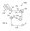
- Fig. 8 One for the arrangement of Fig. 5 very similar arrangement is schematically in Fig. 8 shown. The nature and operation of the components shown results directly from the correspondence of the reference numerals with those in Fig. 5 used reference numerals.
- the Airtum 722 deflects the web 712 obliquely upwards, not obliquely downward as at Fig. 4 ,
Landscapes
- Coating Apparatus (AREA)
- Paper (AREA)
- Drying Of Solid Materials (AREA)
- Application Of Or Painting With Fluid Materials (AREA)
- Cleaning Implements For Floors, Carpets, Furniture, Walls, And The Like (AREA)
Applications Claiming Priority (3)
| Application Number | Priority Date | Filing Date | Title |
|---|---|---|---|
| DE10228114 | 2002-06-24 | ||
| DE10228114A DE10228114A1 (de) | 2002-06-24 | 2002-06-24 | Vorrichtung zum beidseitigen Streichen und zum Trocknen einer Materialbahn, insbesondere aus Papier oder Karton |
| PCT/EP2003/006479 WO2004001133A2 (de) | 2002-06-24 | 2003-06-18 | Vorrichtung zum beidseitigen streichen und zum trocknen einer materialbahn, insbesondere aus papier oder karton |
Publications (3)
| Publication Number | Publication Date |
|---|---|
| EP1516087A2 EP1516087A2 (de) | 2005-03-23 |
| EP1516087B1 EP1516087B1 (de) | 2006-02-15 |
| EP1516087B2 true EP1516087B2 (de) | 2010-01-27 |
Family
ID=29723414
Family Applications (1)
| Application Number | Title | Priority Date | Filing Date |
|---|---|---|---|
| EP03732582A Expired - Lifetime EP1516087B2 (de) | 2002-06-24 | 2003-06-18 | Vorrichtung zum beidseitigen streichen und zum trocknen einer materialbahn, insbesondere aus papier oder karton |
Country Status (6)
| Country | Link |
|---|---|
| EP (1) | EP1516087B2 (enExample) |
| JP (2) | JP2005530606A (enExample) |
| CN (1) | CN100404758C (enExample) |
| AT (1) | ATE317927T1 (enExample) |
| DE (3) | DE20221952U1 (enExample) |
| WO (1) | WO2004001133A2 (enExample) |
Families Citing this family (18)
| Publication number | Priority date | Publication date | Assignee | Title |
|---|---|---|---|---|
| DE10358508A1 (de) * | 2003-12-13 | 2005-07-07 | Voith Paper Patent Gmbh | Auftragsvorrichtung |
| DE102004004154A1 (de) * | 2004-01-28 | 2005-08-18 | Voith Paper Patent Gmbh | Auftragsverfahren |
| JP2007169797A (ja) * | 2005-12-19 | 2007-07-05 | Mitsubishi Heavy Ind Ltd | 塗工シート製造装置および製造方法 |
| DE102008000160A1 (de) | 2008-01-28 | 2009-07-30 | Voith Patent Gmbh | Vorrichtung zur Verbesserung der Arbeitsbedingungen des Bedienpersonals einer Streicheinrichtung |
| DE102008041422A1 (de) * | 2008-08-21 | 2010-02-25 | Voith Patent Gmbh | Vorrichtung zur Erzeugung von beschichteten Papier-, Karton- oder anderen Faserstoffbahnen mit mindestens einer thermosensitiven Schicht und Verfahren zum Betreiben einer derartigen Vorrichtung |
| DE102008041419A1 (de) | 2008-08-21 | 2010-02-25 | Voith Patent Gmbh | Vorrichtung zur Erzeugung von beschichteten Papier-, Karton- oder anderen Faserstoffbahnen mit zumindest einer thermosensitiven Schicht und Verfahren zum Betreiben einer derartigen Vorrichtung |
| CH701535A1 (de) * | 2009-07-17 | 2011-01-31 | Landqart | Vorrichtung zum auftragen von farbeffektpigmenten. |
| DE102010001164A1 (de) * | 2010-01-25 | 2011-07-28 | Voith Patent GmbH, 89522 | Thermopapier- oder Selbstdurchschreibepapiermaschine und Verfahren zur Herstellung von Thermo- oder Selbstdurchschreibepapier |
| AT509419B1 (de) * | 2010-02-03 | 2013-12-15 | Bsw Machinery Handels Gmbh | Verfahren und vorrichtung zum kontinuierlichen beidseitigen beschichten einer gewebebahn |
| KR101309343B1 (ko) | 2010-09-24 | 2013-09-17 | 가부시끼가이샤 도시바 | 양면 도포 시공 장치 및 양면 도포 시공 방법 |
| CN102041706B (zh) * | 2010-11-18 | 2012-01-04 | 天津科技大学 | 一种分段可加热金属带干燥纸张的装置 |
| KR101377589B1 (ko) * | 2012-04-19 | 2014-03-25 | (주)피엔티 | 양면 코팅 장치 |
| JP5914182B2 (ja) * | 2012-06-04 | 2016-05-11 | 日東電工株式会社 | 塗工装置 |
| CN103211472B (zh) * | 2013-05-07 | 2014-10-22 | 黄小群 | 一种双面垫子的制造设备及生产工艺 |
| CN107626538B (zh) * | 2017-10-27 | 2018-08-07 | 深圳市信宇人科技股份有限公司 | 双面涂布方法及装置 |
| WO2019094699A1 (en) * | 2017-11-10 | 2019-05-16 | Nordson Corporation | Systems and methods for coating a substrate |
| FI128981B (en) | 2018-07-27 | 2021-04-30 | Voith Patent Gmbh | Method and apparatus for applying starch |
| CN109453677A (zh) * | 2018-12-19 | 2019-03-12 | 杭州快诊新材料科技有限公司 | 双面亲水膜的制造方法 |
Citations (9)
| Publication number | Priority date | Publication date | Assignee | Title |
|---|---|---|---|---|
| US4455327A (en) † | 1977-03-22 | 1984-06-19 | Fuji Photo Film Co., Ltd. | Dual surface film coating of running web |
| US5122386A (en) † | 1989-05-01 | 1992-06-16 | Fuji Photo Film Co., Ltd. | Double side coating method |
| EP0532486B1 (en) † | 1991-09-05 | 1997-05-14 | Valmet Corporation | Arrangement of nozzles with negative pressure for the treatment of webs |
| EP0905312A2 (en) † | 1997-08-26 | 1999-03-31 | Beloit Technologies, Inc. | Web stabilizing device |
| DE19829449A1 (de) † | 1998-07-01 | 2000-01-05 | Voith Sulzer Papiertech Patent | Auftragsvorrichtung und Auftragsverfahren |
| WO2001016427A1 (en) † | 1999-09-01 | 2001-03-08 | Metso Paper, Inc. | Curtain coater and method for curtain coating |
| DE19962844A1 (de) † | 1999-12-23 | 2001-07-05 | Bachofen & Meier Ag Maschf | Verfahren und Vorrichtung zum Beschichten einer laufenden Materialbahn |
| EP1035254B1 (en) † | 1999-03-12 | 2003-06-04 | Premark RWP Holdings, Inc. | Method for two sided sheet treating |
| EP0943961B1 (en) † | 1998-03-18 | 2004-05-06 | Eastman Kodak Company | Curtain coating apparatus and method with continuous width adjustment |
Family Cites Families (23)
| Publication number | Priority date | Publication date | Assignee | Title |
|---|---|---|---|---|
| US2299026A (en) * | 1938-02-23 | 1942-10-13 | Carle J Merrill | Method of and apparatus for coating paper |
| SE339398B (enExample) * | 1968-11-19 | 1971-10-04 | Klippans Finpappersbruk Ab | |
| US4147126A (en) * | 1976-01-15 | 1979-04-03 | Imperial Chemical Industries Limited | Coating apparatus |
| US4577585A (en) * | 1984-04-23 | 1986-03-25 | Anselmo Anthony G | Method and apparatus for making a color blended wall covering |
| JPS61161177A (ja) * | 1985-01-11 | 1986-07-21 | Fuji Photo Film Co Ltd | 塗布バツクアツプロ−ラへの給電方法 |
| JPH0319021U (enExample) * | 1989-03-01 | 1991-02-25 | ||
| JPH0672601A (ja) * | 1992-08-25 | 1994-03-15 | Konica Corp | 無接触搬送用フローター |
| ATE176508T1 (de) * | 1992-11-03 | 1999-02-15 | Valmet Corp | Verfahren und vorrichtung zum beideseitigen streichen einer dünnen druckpapierbahn |
| DE4318273C2 (de) * | 1993-06-03 | 1999-04-29 | Dietrich Gunter | Vorrichtung zur Farbbeschichtung von Profilstangen mit Abdeckschablone |
| DE4415581C2 (de) * | 1994-05-04 | 1995-12-07 | Voith Gmbh J M | Papier-Streichvorrichtung |
| DE4416399C2 (de) * | 1994-05-09 | 1999-04-01 | Voith Gmbh J M | Trocknungsvorrichtung für eine laufende Materialbahn |
| DE4420242A1 (de) * | 1994-06-10 | 1995-01-05 | Voith Gmbh J M | Einrichtung zur wahlweisen Behandlung einer laufenden Bahn |
| JPH08271145A (ja) * | 1995-03-29 | 1996-10-18 | Konica Corp | 乾燥装置及び乾燥方法 |
| JPH10314660A (ja) * | 1997-05-16 | 1998-12-02 | Teijin Ltd | 連続走行ウェブ用塗布方法およびその装置 |
| DE19743246A1 (de) * | 1997-09-30 | 1999-04-01 | Voith Sulzer Papiertech Patent | Kombinations-Auftragsvorrichtung |
| DE19800954A1 (de) * | 1998-01-13 | 1999-07-15 | Voith Sulzer Papiertech Patent | Vorrichtung zum direkten oder indirekten Auftragen eines flüssigen oder pastösen Auftragsmediums auf eine laufende Materialbahn, insbesondere aus Papier oder Karton |
| US5992040A (en) * | 1998-02-11 | 1999-11-30 | Beloit Technologies, Inc. | Drying section apparatus |
| JP2001180858A (ja) * | 1999-12-24 | 2001-07-03 | Sony Corp | 長尺体搬送装置 |
| DE10012345A1 (de) * | 2000-03-14 | 2001-09-20 | Voith Paper Patent Gmbh | Vorhang-Auftragsvorrichtung |
| DE10057729A1 (de) * | 2000-11-22 | 2002-05-23 | Voith Paper Patent Gmbh | Vorhang-Auftragsvorrichtung |
| FI20011953A0 (fi) * | 2001-10-08 | 2001-10-08 | Metso Paper Inc | Menetelmä ja laitteisto liikkuvan rainan päällystämiseksi |
| JP3944834B2 (ja) * | 2002-03-08 | 2007-07-18 | 株式会社ミヤコシ | 印刷装置 |
| DE10227934A1 (de) * | 2002-06-21 | 2004-01-08 | Voith Paper Patent Gmbh | Verfahren und Vorrichtung zum ein- oder beidseitigen Auftragen eines flüssigen bis pastösen Mediums |
-
2002
- 2002-06-24 DE DE20221952U patent/DE20221952U1/de not_active Expired - Lifetime
- 2002-06-24 DE DE10228114A patent/DE10228114A1/de not_active Withdrawn
-
2003
- 2003-06-18 AT AT03732582T patent/ATE317927T1/de active
- 2003-06-18 WO PCT/EP2003/006479 patent/WO2004001133A2/de not_active Ceased
- 2003-06-18 DE DE50302432T patent/DE50302432D1/de not_active Expired - Lifetime
- 2003-06-18 EP EP03732582A patent/EP1516087B2/de not_active Expired - Lifetime
- 2003-06-18 JP JP2004514790A patent/JP2005530606A/ja active Pending
- 2003-06-18 CN CNB038148749A patent/CN100404758C/zh not_active Expired - Fee Related
-
2009
- 2009-09-24 JP JP2009219510A patent/JP2010017711A/ja active Pending
Patent Citations (9)
| Publication number | Priority date | Publication date | Assignee | Title |
|---|---|---|---|---|
| US4455327A (en) † | 1977-03-22 | 1984-06-19 | Fuji Photo Film Co., Ltd. | Dual surface film coating of running web |
| US5122386A (en) † | 1989-05-01 | 1992-06-16 | Fuji Photo Film Co., Ltd. | Double side coating method |
| EP0532486B1 (en) † | 1991-09-05 | 1997-05-14 | Valmet Corporation | Arrangement of nozzles with negative pressure for the treatment of webs |
| EP0905312A2 (en) † | 1997-08-26 | 1999-03-31 | Beloit Technologies, Inc. | Web stabilizing device |
| EP0943961B1 (en) † | 1998-03-18 | 2004-05-06 | Eastman Kodak Company | Curtain coating apparatus and method with continuous width adjustment |
| DE19829449A1 (de) † | 1998-07-01 | 2000-01-05 | Voith Sulzer Papiertech Patent | Auftragsvorrichtung und Auftragsverfahren |
| EP1035254B1 (en) † | 1999-03-12 | 2003-06-04 | Premark RWP Holdings, Inc. | Method for two sided sheet treating |
| WO2001016427A1 (en) † | 1999-09-01 | 2001-03-08 | Metso Paper, Inc. | Curtain coater and method for curtain coating |
| DE19962844A1 (de) † | 1999-12-23 | 2001-07-05 | Bachofen & Meier Ag Maschf | Verfahren und Vorrichtung zum Beschichten einer laufenden Materialbahn |
Non-Patent Citations (2)
| Title |
|---|
| G. SWIFT - SPOONER INDUSTIES, UK: "Drying options after metering coaters", PAPER ASIA, September 1996 (1996-09-01), pages 32 - 36 † |
| VALMET CORPORATION AIR SYSTEMS: "Valmet turnfloat", VALMET, June 1998 (1998-06-01), FINLAND † |
Also Published As
| Publication number | Publication date |
|---|---|
| DE10228114A1 (de) | 2004-01-15 |
| CN100404758C (zh) | 2008-07-23 |
| CN1662706A (zh) | 2005-08-31 |
| JP2010017711A (ja) | 2010-01-28 |
| EP1516087B1 (de) | 2006-02-15 |
| DE20221952U1 (de) | 2009-08-20 |
| ATE317927T1 (de) | 2006-03-15 |
| JP2005530606A (ja) | 2005-10-13 |
| WO2004001133A3 (de) | 2004-07-08 |
| EP1516087A2 (de) | 2005-03-23 |
| DE50302432D1 (de) | 2006-04-20 |
| WO2004001133A2 (de) | 2003-12-31 |
Similar Documents
| Publication | Publication Date | Title |
|---|---|---|
| EP1516087B2 (de) | Vorrichtung zum beidseitigen streichen und zum trocknen einer materialbahn, insbesondere aus papier oder karton | |
| AT509802B1 (de) | Verfahren und anlage zur behandlung einer faserbahn | |
| EP1367174B1 (de) | Auftragsvorrichtung | |
| AT505228B1 (de) | Verfahren und vorrichtung zum behandeln einer faserbahn | |
| EP0881330A2 (de) | Verfahren und Vorrichtung zum Auftragen eines flüssigen oder pastösen Auftragmediums auf eine laufende Oberfläche | |
| DE102007009702A1 (de) | Verfahren zur Herstellung einer beschichteten Faserstoffbahn, insbesondere aus Papier oder Karton | |
| EP2157240B1 (de) | Vorhang-Auftragsmaschine | |
| DE102010041713A1 (de) | Vorrichtung zum direkten oder indirekten Auftrag von flüssigem bis pastösem Auftragsmedium und Verfahren zum Betreiben einer derartigen Vorrichtung | |
| DE20221930U1 (de) | Maschine zur Behandlung einer Materialbahn vorzugsweise aus Papier und Karton sowie gegebenenfalls zur der Behandlung vorausgehenden Herstellung der Materialbahn, mit einer Kontaktlos-Auftragseinrichtung und einer Materialbahnglättungseinrichtung | |
| EP1198643B1 (de) | Auftragsvorrichtung | |
| DE10359117A1 (de) | Vorhangauftragswerk | |
| EP1375746B1 (de) | Verfahren und Vorrichtung zum ein- oder beidseitigen Auftragen eines flüssigen bis pastösen Mediums | |
| EP1432525B1 (de) | Auftragsvorrichtung | |
| EP2082811A2 (de) | Mehrfach-Vorhangstreichvorrichtung | |
| DE102007033937A1 (de) | Verfahren zur Beschichtung beider Bahnseiten einer laufenden Faserstoffbahn | |
| DE10228134A9 (de) | Maschine zur Herstellung und Behandlung einer Materialbahn mit einer wenigstens ein Kontaktlos-Auftragswerk aufweisenden Auftragseinrichtung | |
| DE19743246A1 (de) | Kombinations-Auftragsvorrichtung | |
| EP1348809A1 (de) | Auftragsvorrichtung | |
| DE102004003899A1 (de) | Vorrichtung zum Führen einer laufenden Faserstoffbahn | |
| DE10125376A1 (de) | Auftragsvorrichtung | |
| DE10333950A1 (de) | Verfahren zum ein- oder beidseitigen Auftragen von flüssigem bis pastösem Auftragsmedium | |
| DE102012205074A1 (de) | Vorrichtung zur Herstellung einer ein- oder beidseitig, ein- oder mehrfach beschichteten Faserstoffbahn | |
| DE19960772A1 (de) | Auftragsverfahren | |
| DE60129409T2 (de) | Vorrichtung zur Beschichtung einer laufenden Bahn, insbesondere einer Papier- oder Kartonbahn | |
| DE102006006157A1 (de) | Vorhang-Auftragsvorrichtung |
Legal Events
| Date | Code | Title | Description |
|---|---|---|---|
| PUAI | Public reference made under article 153(3) epc to a published international application that has entered the european phase |
Free format text: ORIGINAL CODE: 0009012 |
|
| 17P | Request for examination filed |
Effective date: 20041217 |
|
| AK | Designated contracting states |
Kind code of ref document: A2 Designated state(s): AT BE BG CH CY CZ DE DK EE ES FI FR GB GR HU IE IT LI LU MC NL PT RO SE SI SK TR |
|
| 17Q | First examination report despatched |
Effective date: 20050623 |
|
| GRAP | Despatch of communication of intention to grant a patent |
Free format text: ORIGINAL CODE: EPIDOSNIGR1 |
|
| RBV | Designated contracting states (corrected) |
Designated state(s): AT DE FI FR IT SE |
|
| GRAS | Grant fee paid |
Free format text: ORIGINAL CODE: EPIDOSNIGR3 |
|
| RIN1 | Information on inventor provided before grant (corrected) |
Inventor name: HENNINGER, CHRISTOPH Inventor name: TIETZ, MARTIN Inventor name: AUST, RICHARD Inventor name: REICH, STEFAN |
|
| GRAA | (expected) grant |
Free format text: ORIGINAL CODE: 0009210 |
|
| RIN1 | Information on inventor provided before grant (corrected) |
Inventor name: REICH, STEFAN Inventor name: AUST, RICHARD Inventor name: HENNINGER, CHRISTOPH Inventor name: TIETZ, MARTIN |
|
| AK | Designated contracting states |
Kind code of ref document: B1 Designated state(s): AT DE FI FR IT SE |
|
| REF | Corresponds to: |
Ref document number: 50302432 Country of ref document: DE Date of ref document: 20060420 Kind code of ref document: P |
|
| REG | Reference to a national code |
Ref country code: SE Ref legal event code: TRGR |
|
| ET | Fr: translation filed | ||
| RAP2 | Party data changed (patent owner data changed or rights of a patent transferred) |
Owner name: VOITH PATENT GMBH |
|
| PLBI | Opposition filed |
Free format text: ORIGINAL CODE: 0009260 |
|
| PLBI | Opposition filed |
Free format text: ORIGINAL CODE: 0009260 |
|
| 26 | Opposition filed |
Opponent name: VITS SYSTEMS GMBH Effective date: 20061106 |
|
| 26 | Opposition filed |
Opponent name: METSO PAPER, INC. Effective date: 20061114 Opponent name: VITS SYSTEMS GMBH Effective date: 20061106 |
|
| PLAX | Notice of opposition and request to file observation + time limit sent |
Free format text: ORIGINAL CODE: EPIDOSNOBS2 |
|
| PLBB | Reply of patent proprietor to notice(s) of opposition received |
Free format text: ORIGINAL CODE: EPIDOSNOBS3 |
|
| APAH | Appeal reference modified |
Free format text: ORIGINAL CODE: EPIDOSCREFNO |
|
| APBM | Appeal reference recorded |
Free format text: ORIGINAL CODE: EPIDOSNREFNO |
|
| APBP | Date of receipt of notice of appeal recorded |
Free format text: ORIGINAL CODE: EPIDOSNNOA2O |
|
| APBQ | Date of receipt of statement of grounds of appeal recorded |
Free format text: ORIGINAL CODE: EPIDOSNNOA3O |
|
| APBU | Appeal procedure closed |
Free format text: ORIGINAL CODE: EPIDOSNNOA9O |
|
| PUAH | Patent maintained in amended form |
Free format text: ORIGINAL CODE: 0009272 |
|
| STAA | Information on the status of an ep patent application or granted ep patent |
Free format text: STATUS: PATENT MAINTAINED AS AMENDED |
|
| 27A | Patent maintained in amended form |
Effective date: 20100127 |
|
| AK | Designated contracting states |
Kind code of ref document: B2 Designated state(s): AT DE FI FR IT SE |
|
| REG | Reference to a national code |
Ref country code: SE Ref legal event code: RPEO |
|
| PGFP | Annual fee paid to national office [announced via postgrant information from national office to epo] |
Ref country code: SE Payment date: 20110613 Year of fee payment: 9 Ref country code: FR Payment date: 20110630 Year of fee payment: 9 |
|
| PGFP | Annual fee paid to national office [announced via postgrant information from national office to epo] |
Ref country code: FI Payment date: 20110613 Year of fee payment: 9 Ref country code: AT Payment date: 20110613 Year of fee payment: 9 |
|
| PGFP | Annual fee paid to national office [announced via postgrant information from national office to epo] |
Ref country code: DE Payment date: 20110622 Year of fee payment: 9 Ref country code: IT Payment date: 20110621 Year of fee payment: 9 |
|
| REG | Reference to a national code |
Ref country code: SE Ref legal event code: EUG |
|
| PG25 | Lapsed in a contracting state [announced via postgrant information from national office to epo] |
Ref country code: FI Free format text: LAPSE BECAUSE OF NON-PAYMENT OF DUE FEES Effective date: 20120618 |
|
| REG | Reference to a national code |
Ref country code: AT Ref legal event code: MM01 Ref document number: 317927 Country of ref document: AT Kind code of ref document: T Effective date: 20120618 |
|
| PG25 | Lapsed in a contracting state [announced via postgrant information from national office to epo] |
Ref country code: SE Free format text: LAPSE BECAUSE OF NON-PAYMENT OF DUE FEES Effective date: 20120619 Ref country code: IT Free format text: LAPSE BECAUSE OF NON-PAYMENT OF DUE FEES Effective date: 20120618 |
|
| REG | Reference to a national code |
Ref country code: FR Ref legal event code: ST Effective date: 20130228 |
|
| REG | Reference to a national code |
Ref country code: DE Ref legal event code: R119 Ref document number: 50302432 Country of ref document: DE Effective date: 20130101 |
|
| PG25 | Lapsed in a contracting state [announced via postgrant information from national office to epo] |
Ref country code: DE Free format text: LAPSE BECAUSE OF NON-PAYMENT OF DUE FEES Effective date: 20130101 Ref country code: FR Free format text: LAPSE BECAUSE OF NON-PAYMENT OF DUE FEES Effective date: 20120702 |
|
| PG25 | Lapsed in a contracting state [announced via postgrant information from national office to epo] |
Ref country code: AT Free format text: LAPSE BECAUSE OF NON-PAYMENT OF DUE FEES Effective date: 20120618 |