EP1515911B1 - Verfahren und vorrichtung zur abscheidung von nanoröhren oder stickstoffdotierten kohlenstoffnanoröhren mittels pyrolyse - Google Patents
Verfahren und vorrichtung zur abscheidung von nanoröhren oder stickstoffdotierten kohlenstoffnanoröhren mittels pyrolyse Download PDFInfo
- Publication number
- EP1515911B1 EP1515911B1 EP03760783A EP03760783A EP1515911B1 EP 1515911 B1 EP1515911 B1 EP 1515911B1 EP 03760783 A EP03760783 A EP 03760783A EP 03760783 A EP03760783 A EP 03760783A EP 1515911 B1 EP1515911 B1 EP 1515911B1
- Authority
- EP
- European Patent Office
- Prior art keywords
- liquid
- nanotubes
- metal
- carbon
- nitrogen
- Prior art date
- Legal status (The legal status is an assumption and is not a legal conclusion. Google has not performed a legal analysis and makes no representation as to the accuracy of the status listed.)
- Expired - Lifetime
Links
- OKTJSMMVPCPJKN-UHFFFAOYSA-N Carbon Chemical compound [C] OKTJSMMVPCPJKN-UHFFFAOYSA-N 0.000 title claims abstract description 125
- 238000000034 method Methods 0.000 title claims abstract description 98
- 239000002041 carbon nanotube Substances 0.000 title claims abstract description 69
- 229910021393 carbon nanotube Inorganic materials 0.000 title claims abstract description 69
- 238000000197 pyrolysis Methods 0.000 title claims abstract description 45
- 238000000151 deposition Methods 0.000 title description 19
- 239000007788 liquid Substances 0.000 claims abstract description 188
- 238000002347 injection Methods 0.000 claims abstract description 85
- 239000007924 injection Substances 0.000 claims abstract description 85
- IJGRMHOSHXDMSA-UHFFFAOYSA-N Atomic nitrogen Chemical compound N#N IJGRMHOSHXDMSA-UHFFFAOYSA-N 0.000 claims abstract description 79
- 229910052751 metal Inorganic materials 0.000 claims abstract description 69
- 239000002184 metal Substances 0.000 claims abstract description 69
- 239000003054 catalyst Substances 0.000 claims abstract description 66
- 229910052799 carbon Inorganic materials 0.000 claims abstract description 55
- 229930195733 hydrocarbon Natural products 0.000 claims abstract description 52
- 150000002430 hydrocarbons Chemical class 0.000 claims abstract description 52
- 239000002243 precursor Substances 0.000 claims abstract description 52
- 238000006243 chemical reaction Methods 0.000 claims abstract description 42
- 229910052757 nitrogen Inorganic materials 0.000 claims abstract description 40
- 239000002245 particle Substances 0.000 claims abstract description 37
- 239000004215 Carbon black (E152) Substances 0.000 claims abstract description 33
- 239000012159 carrier gas Substances 0.000 claims abstract description 32
- 230000012010 growth Effects 0.000 claims abstract description 28
- 150000001875 compounds Chemical class 0.000 claims abstract description 23
- 230000008021 deposition Effects 0.000 claims abstract description 19
- 150000002736 metal compounds Chemical class 0.000 claims abstract description 19
- 125000004435 hydrogen atom Chemical group [H]* 0.000 claims abstract description 13
- QVGXLLKOCUKJST-UHFFFAOYSA-N atomic oxygen Chemical compound [O] QVGXLLKOCUKJST-UHFFFAOYSA-N 0.000 claims abstract description 12
- 229910052729 chemical element Inorganic materials 0.000 claims abstract description 12
- 239000001301 oxygen Substances 0.000 claims abstract description 12
- 229910052760 oxygen Inorganic materials 0.000 claims abstract description 12
- 125000004432 carbon atom Chemical group C* 0.000 claims abstract description 11
- 125000004429 atom Chemical group 0.000 claims abstract description 9
- 230000000737 periodic effect Effects 0.000 claims abstract description 9
- 125000004433 nitrogen atom Chemical group N* 0.000 claims abstract 6
- 239000002071 nanotube Substances 0.000 claims description 119
- 239000000243 solution Substances 0.000 claims description 111
- YXFVVABEGXRONW-UHFFFAOYSA-N Toluene Chemical compound CC1=CC=CC=C1 YXFVVABEGXRONW-UHFFFAOYSA-N 0.000 claims description 66
- KTWOOEGAPBSYNW-UHFFFAOYSA-N ferrocene Chemical compound [Fe+2].C=1C=C[CH-]C=1.C=1C=C[CH-]C=1 KTWOOEGAPBSYNW-UHFFFAOYSA-N 0.000 claims description 44
- 239000000758 substrate Substances 0.000 claims description 40
- XEEYBQQBJWHFJM-UHFFFAOYSA-N Iron Chemical compound [Fe] XEEYBQQBJWHFJM-UHFFFAOYSA-N 0.000 claims description 38
- UHOVQNZJYSORNB-UHFFFAOYSA-N Benzene Chemical compound C1=CC=CC=C1 UHOVQNZJYSORNB-UHFFFAOYSA-N 0.000 claims description 21
- XDTMQSROBMDMFD-UHFFFAOYSA-N Cyclohexane Chemical compound C1CCCCC1 XDTMQSROBMDMFD-UHFFFAOYSA-N 0.000 claims description 16
- 229910052742 iron Inorganic materials 0.000 claims description 15
- 239000000203 mixture Substances 0.000 claims description 13
- PXHVJJICTQNCMI-UHFFFAOYSA-N Nickel Chemical compound [Ni] PXHVJJICTQNCMI-UHFFFAOYSA-N 0.000 claims description 12
- 239000000725 suspension Substances 0.000 claims description 12
- 239000010453 quartz Substances 0.000 claims description 11
- VYPSYNLAJGMNEJ-UHFFFAOYSA-N silicon dioxide Inorganic materials O=[Si]=O VYPSYNLAJGMNEJ-UHFFFAOYSA-N 0.000 claims description 11
- CTQNGGLPUBDAKN-UHFFFAOYSA-N O-Xylene Chemical compound CC1=CC=CC=C1C CTQNGGLPUBDAKN-UHFFFAOYSA-N 0.000 claims description 10
- KDLHZDBZIXYQEI-UHFFFAOYSA-N Palladium Chemical compound [Pd] KDLHZDBZIXYQEI-UHFFFAOYSA-N 0.000 claims description 10
- 238000001704 evaporation Methods 0.000 claims description 10
- 230000008020 evaporation Effects 0.000 claims description 10
- BASFCYQUMIYNBI-UHFFFAOYSA-N platinum Chemical compound [Pt] BASFCYQUMIYNBI-UHFFFAOYSA-N 0.000 claims description 10
- 239000008096 xylene Substances 0.000 claims description 10
- VLKZOEOYAKHREP-UHFFFAOYSA-N n-Hexane Chemical compound CCCCCC VLKZOEOYAKHREP-UHFFFAOYSA-N 0.000 claims description 9
- 150000003839 salts Chemical class 0.000 claims description 9
- -1 C20 alkanes Chemical class 0.000 claims description 8
- 229920000049 Carbon (fiber) Polymers 0.000 claims description 8
- 239000004917 carbon fiber Substances 0.000 claims description 8
- XUIMIQQOPSSXEZ-UHFFFAOYSA-N Silicon Chemical compound [Si] XUIMIQQOPSSXEZ-UHFFFAOYSA-N 0.000 claims description 7
- 239000004744 fabric Substances 0.000 claims description 7
- 150000002739 metals Chemical class 0.000 claims description 7
- 229910052759 nickel Inorganic materials 0.000 claims description 7
- 229910052710 silicon Inorganic materials 0.000 claims description 7
- 239000010703 silicon Substances 0.000 claims description 7
- WEVYAHXRMPXWCK-UHFFFAOYSA-N Acetonitrile Chemical compound CC#N WEVYAHXRMPXWCK-UHFFFAOYSA-N 0.000 claims description 6
- IMNFDUFMRHMDMM-UHFFFAOYSA-N N-Heptane Chemical compound CCCCCCC IMNFDUFMRHMDMM-UHFFFAOYSA-N 0.000 claims description 6
- 229910052763 palladium Inorganic materials 0.000 claims description 6
- 229910052697 platinum Inorganic materials 0.000 claims description 6
- 229910052707 ruthenium Inorganic materials 0.000 claims description 6
- KMHSUNDEGHRBNV-UHFFFAOYSA-N 2,4-dichloropyrimidine-5-carbonitrile Chemical compound ClC1=NC=C(C#N)C(Cl)=N1 KMHSUNDEGHRBNV-UHFFFAOYSA-N 0.000 claims description 5
- OFBQJSOFQDEBGM-UHFFFAOYSA-N Pentane Chemical compound CCCCC OFBQJSOFQDEBGM-UHFFFAOYSA-N 0.000 claims description 5
- 229910017052 cobalt Inorganic materials 0.000 claims description 5
- 239000010941 cobalt Substances 0.000 claims description 5
- GUTLYIVDDKVIGB-UHFFFAOYSA-N cobalt atom Chemical compound [Co] GUTLYIVDDKVIGB-UHFFFAOYSA-N 0.000 claims description 5
- 239000001257 hydrogen Substances 0.000 claims description 5
- 229910052739 hydrogen Inorganic materials 0.000 claims description 5
- KJTLSVCANCCWHF-UHFFFAOYSA-N Ruthenium Chemical compound [Ru] KJTLSVCANCCWHF-UHFFFAOYSA-N 0.000 claims description 4
- YTPLMLYBLZKORZ-UHFFFAOYSA-N Thiophene Chemical compound C=1C=CSC=1 YTPLMLYBLZKORZ-UHFFFAOYSA-N 0.000 claims description 4
- WGQKYBSKWIADBV-UHFFFAOYSA-N benzylamine Chemical compound NCC1=CC=CC=C1 WGQKYBSKWIADBV-UHFFFAOYSA-N 0.000 claims description 4
- QWTDNUCVQCZILF-UHFFFAOYSA-N isopentane Chemical compound CCC(C)C QWTDNUCVQCZILF-UHFFFAOYSA-N 0.000 claims description 4
- 239000002105 nanoparticle Substances 0.000 claims description 4
- 150000002902 organometallic compounds Chemical class 0.000 claims description 4
- CPLXHLVBOLITMK-UHFFFAOYSA-N Magnesium oxide Chemical compound [Mg]=O CPLXHLVBOLITMK-UHFFFAOYSA-N 0.000 claims description 3
- 239000000956 alloy Substances 0.000 claims description 3
- 229910045601 alloy Inorganic materials 0.000 claims description 3
- WDEQGLDWZMIMJM-UHFFFAOYSA-N benzyl 4-hydroxy-2-(hydroxymethyl)pyrrolidine-1-carboxylate Chemical compound OCC1CC(O)CN1C(=O)OCC1=CC=CC=C1 WDEQGLDWZMIMJM-UHFFFAOYSA-N 0.000 claims description 3
- 150000001924 cycloalkanes Chemical class 0.000 claims description 3
- KZPXREABEBSAQM-UHFFFAOYSA-N cyclopenta-1,3-diene;nickel(2+) Chemical compound [Ni+2].C=1C=C[CH-]C=1.C=1C=C[CH-]C=1 KZPXREABEBSAQM-UHFFFAOYSA-N 0.000 claims description 3
- 239000002082 metal nanoparticle Substances 0.000 claims description 3
- 150000002823 nitrates Chemical class 0.000 claims description 3
- 229910052684 Cerium Inorganic materials 0.000 claims description 2
- 150000001242 acetic acid derivatives Chemical class 0.000 claims description 2
- 125000005595 acetylacetonate group Chemical group 0.000 claims description 2
- 150000001336 alkenes Chemical class 0.000 claims description 2
- 150000001345 alkine derivatives Chemical class 0.000 claims description 2
- 150000004703 alkoxides Chemical class 0.000 claims description 2
- PNEYBMLMFCGWSK-UHFFFAOYSA-N aluminium oxide Inorganic materials [O-2].[O-2].[O-2].[Al+3].[Al+3] PNEYBMLMFCGWSK-UHFFFAOYSA-N 0.000 claims description 2
- 150000001412 amines Chemical class 0.000 claims description 2
- ILZSSCVGGYJLOG-UHFFFAOYSA-N cobaltocene Chemical compound [Co+2].C=1C=C[CH-]C=1.C=1C=C[CH-]C=1 ILZSSCVGGYJLOG-UHFFFAOYSA-N 0.000 claims description 2
- AFABGHUZZDYHJO-UHFFFAOYSA-N dimethyl butane Natural products CCCC(C)C AFABGHUZZDYHJO-UHFFFAOYSA-N 0.000 claims description 2
- 125000005842 heteroatom Chemical group 0.000 claims description 2
- 229910052746 lanthanum Inorganic materials 0.000 claims description 2
- 229910044991 metal oxide Inorganic materials 0.000 claims description 2
- 150000004706 metal oxides Chemical class 0.000 claims description 2
- 150000002825 nitriles Chemical class 0.000 claims description 2
- TVMXDCGIABBOFY-UHFFFAOYSA-N octane Chemical compound CCCCCCCC TVMXDCGIABBOFY-UHFFFAOYSA-N 0.000 claims description 2
- 230000001737 promoting effect Effects 0.000 claims description 2
- FZHCFNGSGGGXEH-UHFFFAOYSA-N ruthenocene Chemical compound [Ru+2].C=1C=C[CH-]C=1.C=1C=C[CH-]C=1 FZHCFNGSGGGXEH-UHFFFAOYSA-N 0.000 claims description 2
- 229930192474 thiophene Natural products 0.000 claims description 2
- 229910052723 transition metal Inorganic materials 0.000 claims description 2
- 150000003624 transition metals Chemical class 0.000 claims description 2
- 229910052727 yttrium Inorganic materials 0.000 claims description 2
- MCMNRKCIXSYSNV-UHFFFAOYSA-N Zirconium dioxide Chemical compound O=[Zr]=O MCMNRKCIXSYSNV-UHFFFAOYSA-N 0.000 claims 2
- ZMIGMASIKSOYAM-UHFFFAOYSA-N cerium Chemical compound [Ce][Ce][Ce][Ce][Ce][Ce][Ce][Ce][Ce][Ce][Ce][Ce][Ce][Ce][Ce][Ce][Ce][Ce][Ce][Ce][Ce][Ce][Ce][Ce][Ce][Ce][Ce][Ce][Ce][Ce][Ce][Ce][Ce][Ce][Ce][Ce][Ce][Ce] ZMIGMASIKSOYAM-UHFFFAOYSA-N 0.000 claims 1
- 229910052593 corundum Inorganic materials 0.000 claims 1
- 150000004820 halides Chemical class 0.000 claims 1
- 230000002452 interceptive effect Effects 0.000 claims 1
- FZLIPJUXYLNCLC-UHFFFAOYSA-N lanthanum atom Chemical compound [La] FZLIPJUXYLNCLC-UHFFFAOYSA-N 0.000 claims 1
- 229910001960 metal nitrate Inorganic materials 0.000 claims 1
- 239000010409 thin film Substances 0.000 claims 1
- 229910001845 yogo sapphire Inorganic materials 0.000 claims 1
- VWQVUPCCIRVNHF-UHFFFAOYSA-N yttrium atom Chemical compound [Y] VWQVUPCCIRVNHF-UHFFFAOYSA-N 0.000 claims 1
- RUDFQVOCFDJEEF-UHFFFAOYSA-N yttrium(III) oxide Inorganic materials [O-2].[O-2].[O-2].[Y+3].[Y+3] RUDFQVOCFDJEEF-UHFFFAOYSA-N 0.000 claims 1
- XKRFYHLGVUSROY-UHFFFAOYSA-N Argon Chemical compound [Ar] XKRFYHLGVUSROY-UHFFFAOYSA-N 0.000 description 40
- 239000000047 product Substances 0.000 description 35
- 230000015572 biosynthetic process Effects 0.000 description 31
- 238000001000 micrograph Methods 0.000 description 30
- 239000010410 layer Substances 0.000 description 26
- 150000002830 nitrogen compounds Chemical class 0.000 description 25
- 238000003786 synthesis reaction Methods 0.000 description 25
- 229910052786 argon Inorganic materials 0.000 description 22
- 239000006227 byproduct Substances 0.000 description 22
- 238000004626 scanning electron microscopy Methods 0.000 description 21
- 238000004519 manufacturing process Methods 0.000 description 16
- 229910017464 nitrogen compound Inorganic materials 0.000 description 16
- 239000007787 solid Substances 0.000 description 13
- 238000002474 experimental method Methods 0.000 description 11
- 239000007789 gas Substances 0.000 description 10
- 238000002360 preparation method Methods 0.000 description 9
- 239000000443 aerosol Substances 0.000 description 8
- 239000000835 fiber Substances 0.000 description 8
- 239000007921 spray Substances 0.000 description 8
- VNWKTOKETHGBQD-UHFFFAOYSA-N methane Chemical compound C VNWKTOKETHGBQD-UHFFFAOYSA-N 0.000 description 6
- 230000003197 catalytic effect Effects 0.000 description 5
- 230000003749 cleanliness Effects 0.000 description 5
- 239000002048 multi walled nanotube Substances 0.000 description 5
- 239000002904 solvent Substances 0.000 description 5
- UFHFLCQGNIYNRP-UHFFFAOYSA-N Hydrogen Chemical compound [H][H] UFHFLCQGNIYNRP-UHFFFAOYSA-N 0.000 description 4
- 229910003481 amorphous carbon Inorganic materials 0.000 description 4
- 238000005229 chemical vapour deposition Methods 0.000 description 4
- 239000000463 material Substances 0.000 description 4
- 239000002923 metal particle Substances 0.000 description 4
- 125000002524 organometallic group Chemical group 0.000 description 4
- 241001080024 Telles Species 0.000 description 3
- HSFWRNGVRCDJHI-UHFFFAOYSA-N alpha-acetylene Natural products C#C HSFWRNGVRCDJHI-UHFFFAOYSA-N 0.000 description 3
- 239000007833 carbon precursor Substances 0.000 description 3
- 238000003421 catalytic decomposition reaction Methods 0.000 description 3
- 238000001311 chemical methods and process Methods 0.000 description 3
- 239000002131 composite material Substances 0.000 description 3
- 125000002534 ethynyl group Chemical group [H]C#C* 0.000 description 3
- 229920000642 polymer Polymers 0.000 description 3
- 238000003860 storage Methods 0.000 description 3
- 230000002194 synthesizing effect Effects 0.000 description 3
- 238000004627 transmission electron microscopy Methods 0.000 description 3
- XLYOFNOQVPJJNP-UHFFFAOYSA-N water Substances O XLYOFNOQVPJJNP-UHFFFAOYSA-N 0.000 description 3
- OCKGFTQIICXDQW-ZEQRLZLVSA-N 5-[(1r)-1-hydroxy-2-[4-[(2r)-2-hydroxy-2-(4-methyl-1-oxo-3h-2-benzofuran-5-yl)ethyl]piperazin-1-yl]ethyl]-4-methyl-3h-2-benzofuran-1-one Chemical compound C1=C2C(=O)OCC2=C(C)C([C@@H](O)CN2CCN(CC2)C[C@H](O)C2=CC=C3C(=O)OCC3=C2C)=C1 OCKGFTQIICXDQW-ZEQRLZLVSA-N 0.000 description 2
- RZVAJINKPMORJF-UHFFFAOYSA-N Acetaminophen Chemical compound CC(=O)NC1=CC=C(O)C=C1 RZVAJINKPMORJF-UHFFFAOYSA-N 0.000 description 2
- CSCPPACGZOOCGX-UHFFFAOYSA-N Acetone Chemical compound CC(C)=O CSCPPACGZOOCGX-UHFFFAOYSA-N 0.000 description 2
- 230000006978 adaptation Effects 0.000 description 2
- 150000001335 aliphatic alkanes Chemical class 0.000 description 2
- 125000003118 aryl group Chemical group 0.000 description 2
- 238000000889 atomisation Methods 0.000 description 2
- 230000005540 biological transmission Effects 0.000 description 2
- 239000011203 carbon fibre reinforced carbon Substances 0.000 description 2
- 239000000919 ceramic Substances 0.000 description 2
- 238000012512 characterization method Methods 0.000 description 2
- 239000003153 chemical reaction reagent Substances 0.000 description 2
- 230000007547 defect Effects 0.000 description 2
- 239000000446 fuel Substances 0.000 description 2
- 229910052734 helium Inorganic materials 0.000 description 2
- 238000002173 high-resolution transmission electron microscopy Methods 0.000 description 2
- 238000005470 impregnation Methods 0.000 description 2
- 239000011159 matrix material Substances 0.000 description 2
- 239000006199 nebulizer Substances 0.000 description 2
- 239000003973 paint Substances 0.000 description 2
- 230000002028 premature Effects 0.000 description 2
- 238000000746 purification Methods 0.000 description 2
- 239000005297 pyrex Substances 0.000 description 2
- 230000002787 reinforcement Effects 0.000 description 2
- 238000000859 sublimation Methods 0.000 description 2
- 230000008022 sublimation Effects 0.000 description 2
- 238000002604 ultrasonography Methods 0.000 description 2
- 229910018072 Al 2 O 3 Inorganic materials 0.000 description 1
- XMWRBQBLMFGWIX-UHFFFAOYSA-N C60 fullerene Chemical class C12=C3C(C4=C56)=C7C8=C5C5=C9C%10=C6C6=C4C1=C1C4=C6C6=C%10C%10=C9C9=C%11C5=C8C5=C8C7=C3C3=C7C2=C1C1=C2C4=C6C4=C%10C6=C9C9=C%11C5=C5C8=C3C3=C7C1=C1C2=C4C6=C2C9=C5C3=C12 XMWRBQBLMFGWIX-UHFFFAOYSA-N 0.000 description 1
- 0 CC[C@]1(C(*)C=CC1C1)C1=*C=C=C Chemical compound CC[C@]1(C(*)C=CC1C1)C1=*C=C=C 0.000 description 1
- VGGSQFUCUMXWEO-UHFFFAOYSA-N Ethene Chemical compound C=C VGGSQFUCUMXWEO-UHFFFAOYSA-N 0.000 description 1
- 239000005977 Ethylene Substances 0.000 description 1
- ISWSIDIOOBJBQZ-UHFFFAOYSA-N Phenol Chemical compound OC1=CC=CC=C1 ISWSIDIOOBJBQZ-UHFFFAOYSA-N 0.000 description 1
- 239000004809 Teflon Substances 0.000 description 1
- 229920006362 Teflon® Polymers 0.000 description 1
- XSQUKJJJFZCRTK-UHFFFAOYSA-N Urea Chemical compound NC(N)=O XSQUKJJJFZCRTK-UHFFFAOYSA-N 0.000 description 1
- 125000000217 alkyl group Chemical group 0.000 description 1
- 238000004458 analytical method Methods 0.000 description 1
- 239000007864 aqueous solution Substances 0.000 description 1
- 150000001491 aromatic compounds Chemical class 0.000 description 1
- 150000004945 aromatic hydrocarbons Chemical class 0.000 description 1
- 239000001273 butane Substances 0.000 description 1
- 230000000711 cancerogenic effect Effects 0.000 description 1
- 239000004202 carbamide Substances 0.000 description 1
- 150000001721 carbon Chemical class 0.000 description 1
- 231100000315 carcinogenic Toxicity 0.000 description 1
- 238000005234 chemical deposition Methods 0.000 description 1
- 238000002485 combustion reaction Methods 0.000 description 1
- 238000004891 communication Methods 0.000 description 1
- 230000001143 conditioned effect Effects 0.000 description 1
- 238000010924 continuous production Methods 0.000 description 1
- 238000001816 cooling Methods 0.000 description 1
- 239000012809 cooling fluid Substances 0.000 description 1
- 239000000498 cooling water Substances 0.000 description 1
- 238000000354 decomposition reaction Methods 0.000 description 1
- 238000011161 development Methods 0.000 description 1
- 238000010891 electric arc Methods 0.000 description 1
- 238000005516 engineering process Methods 0.000 description 1
- 239000012530 fluid Substances 0.000 description 1
- 230000004907 flux Effects 0.000 description 1
- 229910003472 fullerene Inorganic materials 0.000 description 1
- 229910021389 graphene Inorganic materials 0.000 description 1
- 229910052736 halogen Inorganic materials 0.000 description 1
- 150000002367 halogens Chemical class 0.000 description 1
- 238000010438 heat treatment Methods 0.000 description 1
- 239000011261 inert gas Substances 0.000 description 1
- 238000009434 installation Methods 0.000 description 1
- 238000009413 insulation Methods 0.000 description 1
- 238000002955 isolation Methods 0.000 description 1
- 238000011031 large-scale manufacturing process Methods 0.000 description 1
- 238000000608 laser ablation Methods 0.000 description 1
- 231100001231 less toxic Toxicity 0.000 description 1
- 239000012705 liquid precursor Substances 0.000 description 1
- 239000006193 liquid solution Substances 0.000 description 1
- 230000005389 magnetism Effects 0.000 description 1
- 238000000386 microscopy Methods 0.000 description 1
- 239000003595 mist Substances 0.000 description 1
- IJDNQMDRQITEOD-UHFFFAOYSA-N n-butane Chemical compound CCCC IJDNQMDRQITEOD-UHFFFAOYSA-N 0.000 description 1
- 239000002086 nanomaterial Substances 0.000 description 1
- 238000002663 nebulization Methods 0.000 description 1
- 231100000189 neurotoxic Toxicity 0.000 description 1
- 230000002887 neurotoxic effect Effects 0.000 description 1
- QJGQUHMNIGDVPM-UHFFFAOYSA-N nitrogen group Chemical group [N] QJGQUHMNIGDVPM-UHFFFAOYSA-N 0.000 description 1
- 244000045947 parasite Species 0.000 description 1
- 230000003071 parasitic effect Effects 0.000 description 1
- 239000000843 powder Substances 0.000 description 1
- 229910052761 rare earth metal Inorganic materials 0.000 description 1
- 150000002910 rare earth metals Chemical class 0.000 description 1
- 239000002994 raw material Substances 0.000 description 1
- 238000001878 scanning electron micrograph Methods 0.000 description 1
- 239000004065 semiconductor Substances 0.000 description 1
- 239000002356 single layer Substances 0.000 description 1
- 239000002109 single walled nanotube Substances 0.000 description 1
- 239000012265 solid product Substances 0.000 description 1
- 239000010935 stainless steel Substances 0.000 description 1
- 229910001220 stainless steel Inorganic materials 0.000 description 1
- 238000001308 synthesis method Methods 0.000 description 1
- 238000012360 testing method Methods 0.000 description 1
- 238000005979 thermal decomposition reaction Methods 0.000 description 1
- 231100000419 toxicity Toxicity 0.000 description 1
- 230000001988 toxicity Effects 0.000 description 1
- 230000017105 transposition Effects 0.000 description 1
- 238000011282 treatment Methods 0.000 description 1
- 238000011144 upstream manufacturing Methods 0.000 description 1
- 239000012808 vapor phase Substances 0.000 description 1
- 238000009834 vaporization Methods 0.000 description 1
- 230000008016 vaporization Effects 0.000 description 1
- 238000004804 winding Methods 0.000 description 1
Images



Classifications
-
- B—PERFORMING OPERATIONS; TRANSPORTING
- B82—NANOTECHNOLOGY
- B82Y—SPECIFIC USES OR APPLICATIONS OF NANOSTRUCTURES; MEASUREMENT OR ANALYSIS OF NANOSTRUCTURES; MANUFACTURE OR TREATMENT OF NANOSTRUCTURES
- B82Y30/00—Nanotechnology for materials or surface science, e.g. nanocomposites
-
- C—CHEMISTRY; METALLURGY
- C01—INORGANIC CHEMISTRY
- C01B—NON-METALLIC ELEMENTS; COMPOUNDS THEREOF; METALLOIDS OR COMPOUNDS THEREOF NOT COVERED BY SUBCLASS C01C
- C01B32/00—Carbon; Compounds thereof
- C01B32/15—Nano-sized carbon materials
- C01B32/158—Carbon nanotubes
- C01B32/16—Preparation
- C01B32/162—Preparation characterised by catalysts
-
- B—PERFORMING OPERATIONS; TRANSPORTING
- B82—NANOTECHNOLOGY
- B82Y—SPECIFIC USES OR APPLICATIONS OF NANOSTRUCTURES; MEASUREMENT OR ANALYSIS OF NANOSTRUCTURES; MANUFACTURE OR TREATMENT OF NANOSTRUCTURES
- B82Y40/00—Manufacture or treatment of nanostructures
-
- C—CHEMISTRY; METALLURGY
- C01—INORGANIC CHEMISTRY
- C01B—NON-METALLIC ELEMENTS; COMPOUNDS THEREOF; METALLOIDS OR COMPOUNDS THEREOF NOT COVERED BY SUBCLASS C01C
- C01B2202/00—Structure or properties of carbon nanotubes
- C01B2202/08—Aligned nanotubes
-
- C—CHEMISTRY; METALLURGY
- C01—INORGANIC CHEMISTRY
- C01B—NON-METALLIC ELEMENTS; COMPOUNDS THEREOF; METALLOIDS OR COMPOUNDS THEREOF NOT COVERED BY SUBCLASS C01C
- C01B2202/00—Structure or properties of carbon nanotubes
- C01B2202/20—Nanotubes characterized by their properties
- C01B2202/34—Length
Definitions
- the present invention relates to a method and a device for depositing by pyrolysis, more specifically by pyrolysis of a liquid containing at least one liquid hydrocarbon or at least one liquid compound consisting of carbon atoms, nitrogen, and optionally hydrogen atoms and / or other chemical elements such as oxygen, and possibly a metal precursor.
- the technical field of the invention can be defined, in general, as that of the deposit, of the preparation, of carbon nanotubes or of carbon and nitrogen nanotubes (also called carbon nanotubes doped with nitrogen or " nitrogen-doped "), preferably multi-layered and most often aligned with each other.
- the carbon and nitrogen nanotubes are generally designated by the terms “CN” nanotubes or nitrogen-doped carbon nanotubes or “nitrogen-doped” nanotubes.
- a carbon nanotube is defined as the concentric winding of one or more layers of graphene (tiling of carbon hexagons).
- SWNT or Single Wall Nanotube, in English
- MWNT Multi Wall Nanotube
- Carbon nanotubes are attracting increasing interest in various applications in nanotechnology. Indeed, because of their unique structure and their dimensions, characterized by a strong length / diameter ratio, they have exceptional mechanical and electronic properties. In particular, recent studies show that these nanostructures develop a very high tensile strength and that their electrical behavior varies from semiconductor to metal depending on their structure.
- SWNT mono-carbon nanotubes
- MWNT multi-walled carbon nanotubes
- the physical processes consist in sublimating graphitic carbon in the presence or absence of metal. These are basically electric arc methods, laser ablation, or using a solar oven.
- the production yield of these two processes is low, they are, moreover, quite expensive and the production is difficult to control in terms of length and diameter of the nanotubes.
- the nanotubes obtained most often contain a significant amount of by-products, such as encapsulated metal particles, fullerenes and a large amount of amorphous carbon and they are entangled with each other.
- the chemical processes consist mostly of pyrolyzing carbon sources on metal catalysts and strongly resemble the chemical vapor deposition (CVD) process. They constitute a simple way of implementation, more easily controllable and less expensive than physical processes. However, many of these chemical processes still result in the formation of by-products in varying amounts. To overcome this disadvantage and take advantage only of the properties of the nanotubes, it is then necessary to carry out a subsequent purification of the product obtained. The various purification treatments cause imperfections on the surface of the nanotubes, thus modifying some of their properties, as well as an additional cost to the production.
- the first pyrolytic processes used consisted of pyrolyzing carbon sources on metal catalysts placed in a nacelle and previously deposited in an oven.
- the carbon sources were most often gaseous hydrocarbons, such as acetylene, or ethylene or very volatile liquid hydrocarbons, such as benzene transported in the form of steam, and the catalysts were either metal powders, namely: most often iron, nickel or cobalt, or organometallic precursors, namely: most frequently ferrocene.
- the products obtained were multi-walled carbon nanotubes or in certain interlocked mono-walled conditions, covered with an amorphous carbon layer and mixed with various forms of by-products, such as encapsulated metal particles and amorphous carbon filaments in quantity. significant.
- the first aligned nanotubes could be obtained [1, 2, 3, 4 ].
- the synthesis technique involves the vaporization of ferrocene or solid iron phthalocyanine stored in a nacelle located in an oven, which does not provide reproducible and stable vapor flow rates.
- it is difficult to convey these products continuously with a constant flow rate, which is not easily adaptable for continuous or semi-continuous production.
- the first method consists in preparing substrates by impregnation with a salt of the chosen metal or by organizing a network of catalytic elements, placing it in a reactor, and pyrolyzing on the latter either a solid carbon precursor previously vaporized [ 5]. . N. Grobert et al], or a hydrocarbon gas, usually acetylene [e.g. 6 H.Ago et al, 7 Zhang XY et al, 8 Lee et al], or is a solution of... xylene and ferrocene [9 A. Cao et al., 10 BQ Wei et al.], or an aqueous solution of phenol or urea prior nebulized with an ultrasonic nebulizer. [11]
- nanotubes obtained by most of these authors are "clean" and have a high degree of alignment, but their length is less than 60 microns and their growth rate remains low.
- preparation of substrates is a long and rather restrictive step in view of large-scale production.
- colloidal suspensions of metallic nanoparticles introduced into a furnace using a syringe allowed the synthesis of unaligned mono-layered carbon nanotubes [16].
- solutions [12 - 15] is very interesting, easy to implement and easily transferable for production on a larger scale.
- the injection system using a syringe [9, 12] allows a priori to inject a wide range of liquids and also solutions from these liquids.
- it is a continuous injection system that does not cause the formation of a finely divided liquid, which limits the evaporation capacity.
- the liquid being introduced into a first heated zone in its liquid form it is impossible to inject sufficiently large quantities because they would then not be completely transformed in vapor form and may eventually lead to fouling of the heated zone.
- the liquid reservoir is in direct communication with the reactor via the capillary of the syringe, which leads to a partial heating of the solution resulting then a preferential evaporation of the hydrocarbon liquid relative to the metallocene, and in some case premature thermal decomposition of the reagents.
- this connection between the capillary of the syringe and the reactor is a handicap when one wants to be able to operate at controlled pressure in the reaction chamber.
- the liquid is conveyed into the reactor in the form of droplets.
- ultrasonic aerosol generation systems provide access to larger liquid flow rates and have the advantage of independent control of carrier gas flow and liquid flow.
- these aerosol generation systems work well for low viscosity liquids, that is, whose viscosity is typically less than the viscosity of the water, and in the case of solutions obtained from liquids with low viscosity. viscous or volatile, the liquid is preferably nebulized, and the solid remains in the reservoir of solution instead of being fed to the reactor with the same concentration as in the solution.
- the chamber containing the liquid is not isolated from the reactor, which makes it difficult to produce at controlled pressure.
- the above study can also be applied to carbon and nitrogen nanotubes.
- the object of the present invention is to provide a method and a device for the preparation of carbon nanotubes or carbon nanotubes doped with nitrogen which meets, inter alia, the needs indicated above.
- a process for preparing carbon nanotubes or carbon nanotubes doped with nitrogen by pyrolysis in a reaction chamber of a liquid containing at least one carbon precursor liquid hydrocarbon or at least one carbon and nitrogen precursor liquid compound consisting of carbon atoms, nitrogen and optionally hydrogen atoms and / or other chemical elements such as oxygen, and optionally at least one precursor metal compound of a catalyst metal, wherein said pressurized liquid is formed into finely divided liquid particles, such as droplets, by a periodic injection system, and the finely divided particles, such as droplets, thus formed, are conveyed by a stream of carrier gas and introduced into the reaction chamber, where nanotu deposition and growth are carried out. carbon or carbon nanotubes doped with nitrogen.
- the method according to the invention is basically defined by the implementation of a system or specific injection device which is a periodic injection system (discontinuous).
- the system performs the injection discontinuously, is periodically open, and preferably operates at a fixed frequency.
- the opening time and the repetition frequency of this opening are adjustable parameters.
- This injection system makes it possible to inject all kinds of liquids, both in the form of solutions and suspensions, and preferably makes it possible to cover a wide range of injection rates.
- the injection system is of the discontinuous (periodic) automotive thermal motor injector type; preferably further, it is provided with a valve of the needle valve type.
- This specific injection system is used, fed according to the invention, with a specific liquid which contains at least one carbon precursor hydrocarbon forming the nanotubes that are aimed at synthesizing or at least one liquid compound. consisting of carbon atoms, nitrogen, and optionally hydrogen atoms and / or other chemical elements, such as oxygen (called “nitrogen compound”) and, optionally, at least one organometallic compound or metal precursor metal which acts as a catalyst for the preparation, deposition, synthesis of carbon nanotubes or carbon nanotubes doped with nitrogen.
- a specific liquid which contains at least one carbon precursor hydrocarbon forming the nanotubes that are aimed at synthesizing or at least one liquid compound. consisting of carbon atoms, nitrogen, and optionally hydrogen atoms and / or other chemical elements, such as oxygen (called “nitrogen compound”) and, optionally, at least one organometallic compound or metal precursor metal which acts as a catalyst for the preparation, deposition, synthesis of carbon nanotubes or carbon nanotubes doped with nitrogen.
- nitrogen compound
- liquid which is put in the form of droplets in the process of this document is consisting of very volatile solvents, in which the solid precursors are dissolved.
- the solvent only serves to convey the solid precursor to the CVD chamber and is removed before the deposition reaction - oxide - occurs on the substrate.
- the solvent does not participate, in any way, in the synthesis of the prepared layers, for example prepared oxide layers, and it provides none of the elements constituting these layers, it serves only vehicle, vector, passive.
- the liquid hydrocarbon or the liquid nitrogen compound is the precursor of carbon or carbon and nitrogen forming the nanotubes, it is therefore a real reagent (and not a simple solvent or passive vehicle) playing a fundamental role, which plays a major role in the formation of nanotubes and provides the essential raw material for the synthesis, deposition and growth of carbon nanotubes or carbon nanotubes doped with nitrogen.
- liquid hydrocarbon or the nitrogenous compound is not removed before the reaction chamber, as a solvent, FR-A-2,707,671 it penetrates into it and it is its pyrolysis in the presence of the metal catalyst which forms the carbon nanotubes or nitrogen-doped carbon nanotubes sought.
- finely divided liquid particles particles of a size of a few tenths of a micron to a few tens of microns. These particles are preferably in the form of droplets, but other forms can be envisaged.
- These particles in particular these droplets generally form a mist or a jet of droplets.
- the method according to the invention is simple, reliable, reproducible and allows the preparation of carbon nanotubes or carbon nanotubes doped with nitrogen, in particular carbon nanotubes or nitrogen-doped carbon nanotubes multi-layers, "clean" is ie essentially free of by-products, aligned, and of controllable length.
- the process according to the invention can be carried out easily, on a large scale, to produce large quantities of nanotubes.
- the nanotubes are obtained with a high yield, for example from 200 to 1700%, and the growth rate of the nanotubes is very high, which reduces the duration of the process which is very small compared with the processes of the art. prior.
- the nanotubes obtained according to the invention are regularly arranged, arranged in space, and, generally, are aligned with each other and substantially perpendicular to the wall of the reaction chamber. When they are prepared directly in the reaction chamber, such as a reactor, they generally uniformly cover the walls of the reactor.
- the nanotubes obtained which are of excellent quality, in terms of cleanliness and alignment, can, in addition, have very large lengths, for example from one to a few microns (for example, 1 to 10 microns) to a to a few millimeters (for example, 1 to 10 mm).
- Such a length is, in addition, obtained quickly in a shorter time than that required with other methods.
- the method according to the invention solves, inter alia, the problems enumerated above.
- the specific injection system preferably of the discontinuous automotive thermal motor injector type, preferably provided with a valve of the needle valve type, used in the method of the invention, allows the injection of a large variety of solutions, compositions, different concentrations, made, for example, from different types of liquid hydrocarbons or different types of liquid nitrogen compounds and rapid growth of nanotubes.
- the technique of introducing liquids, such as solutions in a reaction chamber in the form of finely divided liquid particles, for example droplets, using the specific injection system according to the invention is controllable, reliable, reproducible and much more flexible than the techniques listed above, which implement a syringe, a "sprayer” or an ultrasonic nebulizer.
- the flexibility of this technique allows, in particular, the use of solutions consisting of volatile carbonaceous liquids and less toxic than benzene, although the use of these is still possible.
- liquid hydrocarbons or liquid nitrogen compounds can be used in the process of the invention: in fact, thanks to the specific injection system used according to the invention, surprisingly, any liquid based on any types of liquid hydrocarbons or liquid nitrogen compounds may be used, even liquids which were then never used for this purpose or even envisaged for it.
- liquid hydrocarbon (or liquid hydrocarbons, if there are several) is selected from non-aromatic liquid hydrocarbons (at room temperature).
- Non-aromatic liquid hydrocarbons at room temperature include, for example: alkanes of 5 to 20C, such as n-pentane, isopentane, hexane, heptane and octane; alkenes liquid from 5 to 20C; liquid alkynes from 4 to 20C; and cycloalkanes of 5 to 15C, such as cyclohexane.
- alkanes of 5 to 20C such as n-pentane, isopentane, hexane, heptane and octane
- alkenes liquid from 5 to 20C liquid alkynes from 4 to 20C
- cycloalkanes of 5 to 15C such as cyclohexane.
- nonaromatic liquid hydrocarbons and in particular hexane, heptane and cyclohexane are more volatile than the optionally substituted aromatic liquid hydrocarbons, such as benzene, toluene and xylene, and can therefore be used for the first time , in the process for the preparation of carbon nanotubes according to the invention, thanks to the particular injection system which is implemented therein.
- Liquid alkanes and cycloalkanes such as cyclohexane, have the advantage of lower toxicity than benzene which is carcinogenic and toluene and xylene which are neurotoxic.
- aromatic hydrocarbons of 6 to 12C optionally substituted, for example by less an alkyl group of 1 to 6 C, such as benzene, toluene and xylene can also be used.
- the liquid nitrogen compound is preferably chosen from liquid amines, for example benzylamine, or from nitriles such as acetonitrile.
- the liquid may contain a single hydrocarbon (or nitrogen compound) or a mixture of several hydrocarbons (or nitrogen compounds), in all proportions.
- the liquid in the form of finely divided liquid particles, for example droplets, is preferably in the form of a solution of the precursor metal compound (s), said metal being catalytic role in the hydrocarbon (s) liquid (s).
- Said precursor metal compound of a catalyst metal also called "precursor of the metal acting as a catalyst", when it is present in the solution, is generally chosen from compounds consisting of carbon, hydrogen or possibly nitrogen. and / or oxygen and at least one metal.
- Said metal precursor compound of a catalyst metal may thus be chosen, for example, from metal salts and organometallic compounds.
- Said metal salts may be chosen from metal salts whose counter-ion of the metal is constituted by a heteroatom, such as a halogen.
- Said metal salts may be chosen from nitrates, acetates, acetylacetonates, and metal phthalocyanines, such as iron phthalocyanine and nickel phthalocyanine.
- the metal is generally selected from iron, cobalt, nickel, ruthenium, palladium and platinum.
- Preferred compounds are ferrocene, nickelocene, cobaltocene, ruthenocene, iron phthalocyanine and nickel phthalocyanine.
- the solution may consist of either an organometallic solid compound, or a mixture of solid compounds, dissolved in the liquid hydrocarbon or the liquid nitrogen compound or in a mixture of liquid hydrocarbons or in a mixture of liquid nitrogen compounds, the only embodiment condition is the solubility of the solid product in the contemplated liquid.
- the concentration of the precursor metal compound (s) of a catalyst metal in the solution is generally from 0.2 to 15% by weight.
- the liquid may also be in the form of a colloidal suspension of particles or, more precisely , metal nanoparticles in said at least one liquid hydrocarbon or in said at least one liquid nitrogen compound.
- the liquid may also be in the form of a colloidal suspension of particles in which is dissolved (s), in addition, one or more metal precursors such as those mentioned above.
- the suspension liquid plays the role of a carbon source or a carbon and nitrogen source, as in the case where the liquid is a solution. It is understood that the liquid may consist of a single or a mixture of two or more of the liquid hydrocarbons mentioned above. Alternatively, the liquid may consist of a single or a mixture of two liquid nitrogen compounds.
- the nanoparticles are chosen from nanoparticles of iron, nickel, cobalt, ruthenium, palladium, platinum, etc., and their mixtures or their alloys: namely, the alloys of two or more of these metals, with each other, or with other metals.
- the liquid may contain, in addition, one or more compound (s) promoting the growth of carbon nanotubes or nanotubes of carbon and nitrogen (doped with water).
- nitrogen such as thiophene or rare earth precursors (such as Y, La, Ce, for example nitrates or alkoxides thereof).
- the finely divided liquid particles such as droplets
- the injection system generally operates in pulses, the number of pulses is generally from 0.9 to 1200 per minute.
- this volume may be, for example, from 2 to 100 microliters.
- the finely divided liquid particles such as the droplets formed by the injection system are, prior to their introduction into the reaction chamber, evaporated in an evaporation device.
- the pyrolysis is carried out at a temperature of 600 to 1100 ° C, preferably 800 to 1000 ° C, more preferably 800 to 900 ° C.
- the pyrolysis is carried out for a period of 5 to 60 min, preferably 15 to 30 minutes. This time obviously varies depending on the size of the reactor.
- the pressure in the reaction chamber is a controlled pressure, for example less than atmospheric pressure.
- Carbon nanotubes or carbon nanotubes doped with nitrogen can be prepared directly on the walls of the reaction chamber, which thus serve as a support for their deposition and growth.
- the liquid must contain a compound of metal, a precursor of a metal acting as a catalyst.
- the liquid does not contain a precursor metal compound of a catalyst metal and the substrate is provided with catalyst deposition.
- the liquid contains one or more precursor metal compound (s) of a catalyst metal and the substrate is provided or not provided with catalyst deposition.
- the substrate should contain a deposit of catalyst (s) metal (s)
- the precursor of the metal acting as a catalyst is in the solution, ie the injected liquid consists of hydrocarbon (s) or nitrogen compound (s) and metal precursor (s)
- the substrate may contain or not contain a catalyst deposit (s) metal (s).
- the deposition and the growth can be carried out on any type of substrate, provided that this substrate is resistant to pyrolysis temperature.
- the substrate may be chosen, for example, from quartz, silicon substrates and metal oxide substrates, such as Al 2 O 3 , Y 2 O 3 , MgO and ZrO 2 .
- the substrate may also be a fabric of carbon fibers or carbon fibers doped with nitrogen.
- the substrate may, prior to the deposition and growth of the nanotubes, be provided with a catalyst deposit, in which case the injected liquid may not contain a precursor metal compound of a metal acting as a catalyst.
- this catalyst deposition comprises one or more metals generally chosen from transition metals, such as Fe, Ni, Co and other metals such as Pd, Ru and Pt.
- the catalyst deposit may be in the form of a thin layer, but it may also be deposited discontinuously.
- the deposit When the deposit is discontinuous, it can be ordered or not and is in the form of a set of discrete entities, for example, drops, pads, spots or catalyst points.
- the deposit is ordered, organized, said discrete entities, are generally arranged in the form of a network or pattern, and it is possible to generate carbon nanotubes or nitrogen-doped carbon nanotubes also arranged in a network. , in a pattern, for example in a pattern in which the nanotubes are aligned, for example in a regular pattern.
- the nanotube patterns that can be obtained on substrates and that can be field-emission tested are an array of interconnected nanotube lines or rows.
- the substrate may also consist of a layer of carbon nanotubes or nitrogen-doped carbon nanotubes or several superimposed layers of nanotubes.
- the side wall of the connecting ring comprises at least one carrier gas inlet tube, said carrier gas inlet tube opening into an annular groove surrounding the injection head of the liquid particle injection system and placed behind it, in order to surround the finely divided liquid particles without disturbing them.
- the method according to the invention can be implemented, for example, with a device, such as that described on the figure 1 .
- This device may, in general, be divided into four or five parts, depending on whether or not it comprises an evaporator.
- the device comprises, firstly, means for supplying the liquid injection system.
- these means comprise an enclosure or reservoir (1), for example made of stainless steel, containing the liquid (2), which is connected to the inlet of the injection system of the injector via a conduit, for example made of Teflon ® (3). All of these supply means is provided to be able to be subjected to a pressure for conveying the liquid to the injector.
- This pressure may, for example, result from the introduction into the upper part of the enclosure or reservoir, that is to say in the part (4) located above the liquid level, a gas under pressure (5), namely whose pressure is generally 1 to 5 times the atmospheric pressure.
- This gas may be similar to the carrier gas but it is not necessarily the same gas, it must however be inert, it is therefore generally selected from inert gases such as Ar, He, N 2 , ....
- the chamber or tank (1) is intended to be stored at ambient temperature or at any temperature that does not cause reactions within the liquid, such as a solution.
- the device then comprises injection means (6) which, according to the invention, preferably comprise an injector of the type injector for a combustion engine used in the automobile sector, means for controlling said injector, generally constituted by a housing controlled by a microprocessor system and finally a connection ring (7) of the injector to an evaporator (8) or directly to the reaction chamber or reactor (9).
- injection means (6) which, according to the invention, preferably comprise an injector of the type injector for a combustion engine used in the automobile sector, means for controlling said injector, generally constituted by a housing controlled by a microprocessor system and finally a connection ring (7) of the injector to an evaporator (8) or directly to the reaction chamber or reactor (9).
- Said connecting ring comprises a cooling fluid circuit, such as water, and an inlet of the carrier gas (10).
- the carrier gas may be any, but it is generally selected from Ar, He, N 2 , H 2 ,... Or mixtures thereof.
- the carrier gas is argon or a mixture of argon and hydrogen.
- the injection system preferably operates in pulsed mode, and allows to inject at each actuation a set of droplets of a given volume.
- the pressure above the liquid level, located in the storage tank or enclosure (1), must be greater than that in the evaporator (8) or the reactor (9) .
- the injector is composed of a valve of the needle valve type which is controlled in duration and frequency of opening.
- the duration of opening is generally from 0.5 to 12 milliseconds and the opening frequency is from 0.016 to 20 Hz.
- the duration of the opening makes it possible to control the volume of the droplets and the total duration of injection is fixed by the injection frequency and the number of pulses.
- the total injection time is generally 5 to 60 minutes.
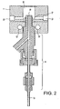
- the injector assembly (6) and connecting ring (7) is shown in lateral section, the stitching (14) provides an output to a microprocessor control box (not shown) and an orifice (10) allows an arrival of vector gas.
- the figure 2 is an enlarged sectional top view of the injector assembly (6) and connecting ring (7), showing the arrival of carrier gas (10), and the bores (15) for the circulation of the cooling water .
- the connecting ring (7) is connected at (16) to the evaporator.
- carrier gas (10) at the connection ring is designed so as not to disturb all the droplets emitted by the injector (18). It consists of a circular or rather annular groove or groove (19) located behind the injection head (18) (in the drawing, it is the notch on which the conduit 10 opens).
- the solution or suspension that comes under pressure through the pipe (17) is put in finely divided form, for example in the form of droplets in the injector (6). and these droplets are emitted at (18) by the injection head of the injection system into the evaporator, and conveyed to the reactor by the carrier gas introduced into (10), then distributed by the groove 19, surrounding the injection head.
- the carrier gas thus surrounds the finely divided particles without disturbing them.
- the device of the figure 1 may, optionally, include evaporation means which may be, for example, in the form of a heated metal tube (8), placed before the reaction chamber.
- evaporation means which may be, for example, in the form of a heated metal tube (8), placed before the reaction chamber. This evaporation system is intended to evaporate the droplets emitted by the injector.
- This evaporation system is optional in that it is not necessary in all operating conditions. In particular, when the injected solution flow rates are low relative to the reactor volume capacity and the carrier gas flow, then it is not necessarily necessary to use the evaporator.
- Another part of the device of the figure 1 to implement the method of the invention, is located by the reaction chamber which is provided with means for bringing it to the pyrolysis temperature of the injected liquid.
- the reaction chamber or reactor (9) is generally tubular in shape and is generally made of a material, such as quartz, alumina, or any material resistant in the temperature range 600 - 1100 ° C.
- These means for bringing the reaction chamber to the pyrolysis temperature generally comprise an oven (11), for example a tubular oven or section square, in which is placed the reaction chamber (9).
- the oven (11) is generally controlled by a temperature controller.
- the last part of the device of the figure 1 is the gas evacuation part and consists, for example, of a gas cooling system (12) resulting from the reactions which have occurred in the reaction chamber, followed by a trap cooled to the temperature of ice (13) and a bubbler in acetone.
- a gas cooling system (12) resulting from the reactions which have occurred in the reaction chamber, followed by a trap cooled to the temperature of ice (13) and a bubbler in acetone.
- the trap (13) can be replaced by a filter system.
- the operating time, of production is not only conditioned by the capacity of the reactor, but also by the desired degree of cleanliness of the nanotubes produced in time, that is to say that the quality of the nanotubes can possibly degrade after a certain production time.
- the aligned and long nanotubes produced by the process of the invention can be used in very varied fields such as the mechanical reinforcement of various matrices, for example polymers, ceramics, or metals.
- They can also make materials more functional, for example imparting conduction or magnetism properties to certain polymers.
- nanotubes produced by the process of the invention which are aligned perpendicular to substrates, can be used as field emission sources, for example in flat screen devices.
- field emission sources for example in flat screen devices.
- a last area where these materials can find an application is that of new energy technologies, such as for example the electrodes for fuel cells.
- carbon nanotubes are prepared by the method of the invention, by implementing with the installation described on the figure 1 .
- aligned nanotubes are prepared directly in the reactor from solutions of ferrocene in toluene.
- the liquid hydrocarbon used is toluene and the precursor of the metal (Fe) acting as a catalyst is ferrocene.
- the solid ferrocene is dissolved in toluene using an ultrasound tank.
- the resulting solution is then poured into the liquid chamber and a pressure of 1 bar of argon is applied to push the liquid to the injector.
- the solution is a 5% by weight solution of ferrocene.
- the observations by scanning electron microscopy show the presence of layers of nanotubes aligned in the image of a carpet.
- the thickness of these plies, ie the length of the nanotubes increases as the pyrolysis temperature increases, it is about 150 microns at 850 ° C. and about 400 microns at 900 ° C.
- the growth rates at these two pyrolysis temperatures are respectively 10 ⁇ m / min. and 27 ⁇ m / min.
- Transmission electron microscopy observations of individual nanotubes highlight the multi-layered structure. Under the synthesis conditions stated above, there remains within the carbon product a small proportion of by-products in the form of agglomerates of carbonaceous particles.
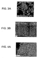
- the micrograph of the figure 3A relates to carbon products, as collected after synthesis, obtained by pyrolysis at 850 ° C of a solution as described above. It shows all of the sample consists of several packets of aligned nanotubes, resembling "pieces of carpet".
- the micrograph of the figure 3B relates to the carbon products, as collected after the synthesis obtained by pyrolysis at 900 ° C of the solution described above, it shows the edge of a nanotube packet aligned with some agglomerates of particles.
- the solution is a 2.5% by weight solution of ferrocene.
- the thickness of the plies ie the length of the nanotubes increases as the pyrolysis temperature increases, is about 100 microns at 800 ° C., 280 microns at 850 ° C. and 400 microns at 900 ° C.
- the growth rates at these three pyrolysis temperatures are respectively 7 ⁇ m / min., 19 ⁇ m / min., And 27 ⁇ m / min. It is also multi-sheet nanotubes.
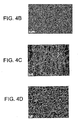
- Micrographs of Figures 4A to 4D relate to the carbon products, as collected after the synthesis obtained by pyrolysis of a 2.5% solution of ferrocene in toluene.
- the micrograph of the Figure 4A for which the synthesis was performed at 800 ° C, represents the slice of a bundle of nanotubes aligned and "clean" with a virtual absence of by-products.
- the micrograph of the Figure 4B for which the synthesis was carried out at 800 ° C represents the surface of a pack of aligned nanotubes, with the end of the nanotubes pointing upwards.
- the micrograph of the figure 4C for which the synthesis was carried out at 850 ° C is a high magnification micrograph of the slice of a pack of aligned nanotubes, confirming the near-absence of by-products.
- the micrograph of the figure 4D for which the synthesis was carried out at 850 ° C is a high magnification micrograph of the surface of a pack of aligned nanotubes showing the end of the nanotubes pointing upwards and the surface cleanliness.
- the mass of product obtained is 736 mg and the yield relative to the initial mass of catalyst increases in the absence of evaporator (127% compared to 840% in the presence of the evaporator).
- the nanotubes obtained are always aligned like a carpet and we can see the virtual absence of by-products.
- the thickness of the nanotube layers is about 380 microns.
- the growth rate is 25 ⁇ m / min.
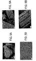
- Micrographs of Figures 5A to 5B carried out under a scanning electron microscope, concern the carbon products, as collected after synthesis, obtained by pyrolysis at 850 ° C. of a 2.5% solution of ferrocene in toluene, without using an evaporator.
- the micrograph of the Figure 5A gives an overall appearance of the sample, showing bundles of aligned nanotubes, free of by-products.
- the micrograph of the Figure 5B shows the surface that can be described as very clean of a bundle of aligned nanotubes pointing upwards.
- the yield relative to the initial mass of catalyst remains high, namely: 1351%, and the mass of product obtained reaches 1.741 g.
- Observation by scanning electron microscopy shows layers of aligned nanotubes containing a very high proportion of nanotubes, that is to say almost free of by-products.
- the thickness of the layers is extremely high since it can reach 1 mm, and the degree of alignment of the nanotubes within the layers is very important.
- the growth rate is 33 ⁇ m / min.
- Micrographs of Figures 6A and 6B relate to the carbon products, as collected after synthesis, obtained by pyrolysis at 850 ° C of a 2.5% solution of ferrocene in toluene without using an evaporator.
- the micrograph of the Figure 6A gives an overall appearance of the sample showing aligned bundles of nanotubes, free of by-products.
- the micrograph of the Figure 6B shows the slice of a bundle of aligned nanotubes that can be described as clean.
- aligned nanotubes are prepared directly in the reactor from solutions of ferrocene in xylene.
- the liquid hydrocarbon used is xylene and the precursor of the metal (Fe) acting as a catalyst is ferrocene.
- the solid ferrocene is dissolved in xylene using an ultrasonic bath.
- the resulting solution is then poured into the liquid chamber (see figure 1 ) and a pressure of 1 bar of argon is applied in order to push the liquid towards the injector.
- the solution is a 5% by weight solution of ferrocene.
- 2,701 injections of droplets were made at a frequency of 180 injections per minute.
- the opening time of the needle valve is 0.75 milliseconds.
- the duration of the experiment is therefore 15 minutes and the mass of solution injected is 10.5 grams or about 0.158 grams of iron acting as a catalyst.
- the carrier gas is argon at a rate of 1 liter per minute.
- the pyrolysis temperature is 850 ° C.
- a carbonaceous deposit was obtained on the walls of the reactor, and the mass of product was 1.063 grams. This result leads to a yield of carbon product with respect to the initial Fe catalyst mass of 574%.
- the micrograph of the figure 7 carried out under a scanning electron microscope, shows the whole of the sample obtained after synthesis, which is in the form of packets of aligned nanotubes.
- the solution is a solution at 2.5% by weight of ferrocene.
- 2,701 injections of droplets were made at a frequency of 180 injections per minute.
- the opening time of the needle valve is 0.75 milliseconds.
- the duration of the experiment is therefore 15 minutes and the mass of solution injected is 11.2 grams, or about 0.084 grams of iron acting as a catalyst.
- the carrier gas is argon at a rate of 1 liter per minute.
- the pyrolysis temperature is 850 ° C.
- the carbonaceous deposition mass obtained on the walls of the reactor is 1.096 grams. This result leads to a yield of carbon product relative to the initial Fe catalyst mass of 1 205%.
- the thickness of the nanotube layers observed in scanning electron microscopy is about 200 microns.
- the growth rate is 13 ⁇ m / min. In this case, there still remains within the carbon product a small proportion of by-products which is lower than in the case of the synthesis conditions mentioned in Example 2A.
- nanotubes aligned directly in the reactor are prepared from ferrocene solutions in cyclohexane.
- the liquid hydrocarbon used was cyclohexane and the precursor of the metal (Fe) acting as a catalyst was ferrocene.
- the solid ferrocene is dissolved in cyclohexane by means of an ultrasonic bath. The resulting solution is then poured into the liquid chamber (see figure 1 ) and a pressure of 1 bar of argon is applied in order to push the liquid towards the injector.
- the solution is a 5% by weight solution of ferrocene.
- 2,701 injections of droplets were made at a frequency of 180 injections per minute.
- the opening time of the needle valve is 0.75 milliseconds.
- the duration of the experiment is therefore 15 minutes and the mass of solution injected is 9.1 grams, or about 0.137 grams of iron acting as a catalyst.
- the carrier gas is argon at a rate of 1 liter per minute.
- the pyrolysis temperature is 850 ° C.
- the carbonaceous deposition mass obtained on the walls of the reactor is 691 mg. This result leads to a yield of carbon product with respect to the initial Fe catalyst mass of 406%.
- the micrograph of the figure 8A performed by scanning electron microscopy, shows the entire sample, which is in the form of packets of aligned nanotubes.
- the micrograph of the Figure 8B shows the slice of a pack of aligned nanotubes containing a small amount of by-products in the form of particle agglomerates.
- the solution is a 2.5% by weight solution of ferrocene.
- 2,701 injections of droplets were made at a frequency of 180 injections per minute.
- the opening time of the needle valve is 0.75 milliseconds.
- the duration of the experiment is therefore 15 minutes and the mass of solution injected is 8.6 grams, or about 0.064 grams of iron acting as a catalyst.
- the carrier gas is argon at a rate of 1 liter per minute.
- the pyrolysis temperature is 850 ° C.
- the carbonaceous deposit mass obtained on the walls of the reactor is 1.168 grams. This result leads to a yield of carbon product with respect to the initial Fe catalyst mass of 1710%.
- the sheets of nanotubes observed by scanning electron microscopy are extremely "clean" that is to say almost free of by-products, and their thickness can reach 950 microns.
- the growth rate is 63 ⁇ m / min.
- Micrographs of Figures 9A to 9D performed by scanning electron microscopy respectively show: the whole of the sample which is in the form of packets of nanotubes aligned, very clean ( Figures 9A and 9B ), the slice of a bundle of aligned nanotubes, virtually free of by-products ( Figure 9C ) and finally the degree high alignment of the nanotubes within the slice of a nanotube bundle ( Figure 9D ).
- the length can be controlled in particular by the duration and temperature of pyrolysis and the nature of the liquid hydrocarbon used.
- the pyrolysis of toluene solutions at 2.5% ferrocene for 30 min as well as the pyrolysis of cyclohexane solutions at 2.5% ferrocene for 15 min. allows the production of very long nanotubes (of the order of a millimeter) and extremely clean.
- nanotubes are prepared on substrates from solutions of ferrocene in toluene.
- the liquid hydrocarbon used is toluene and the precursor of the metal (Fe) acting as catalyst is ferrocene at a rate of 2.5% in the solution.
- the solid ferrocene is dissolved in toluene using an ultrasound tank.
- the resulting solution is then poured into the liquid chamber (see figure 1 ) and a pressure of 1 bar of argon is applied in order to push the liquid towards the injector.
- Quartz or silicon substrates have a square section of about 1 x 1 cm. They are previously placed in the pyrolysis reactor.
- 2,566 injections of droplets were made at a frequency of 171 injections per minute.
- the opening time of the needle valve is 0.75 milliseconds.
- the duration of the experiment is therefore 15 minutes and the mass of solution injected was 8 grams, or about 0.06 grams of iron acting as a catalyst.
- the carrier gas is argon at a rate of 1 liter per minute.
- the pyrolysis temperature is 850 ° C.
- a carbonaceous deposit is obtained both on the reactor walls and on the quartz or silicon substrate. With the naked eye, this deposit appears relatively homogeneous.
- the observations by scanning electron microscopy show that the carbonaceous deposit consists of nanotubes aligned perpendicular to the quartz or silicon substrate. The degree of alignment is high and the nanotubes are virtually free of byproducts.
- the thickness of the nanotube layer deposited on the substrates is about 370 microns.
- the growth rate is 24 ⁇ m / min.
- the micrograph of the figure 10 performed by scanning electron microscopy, shows the nanotubes aligned perpendicularly to the surface of a quartz substrate.
- the square-section carbon fiber fabric of about 1 x 1 cm is pre-placed in the pyrolysis reactor.
- Example 4A The injection and pyrolysis parameters are identical to those mentioned in Example 4A.
- a carbonaceous deposit is obtained both on the walls of the reactor and on the surface of the carbonaceous fabric. With the naked eye, this deposit appears relatively homogeneous.
- Micrographs of Figures 11A and 11B carried out by scanning electron microscopy, shows entangled nanotubes deposited on the surface of the fibers or in inter-fiber spaces.
- Example 4 It follows from Example 4 that it is therefore possible to grow aligned and "clean" nanotubes on quartz or silicon substrates.
Landscapes
- Chemical & Material Sciences (AREA)
- Engineering & Computer Science (AREA)
- Nanotechnology (AREA)
- Materials Engineering (AREA)
- Condensed Matter Physics & Semiconductors (AREA)
- General Physics & Mathematics (AREA)
- Physics & Mathematics (AREA)
- Crystallography & Structural Chemistry (AREA)
- Organic Chemistry (AREA)
- Composite Materials (AREA)
- Chemical Kinetics & Catalysis (AREA)
- Inorganic Chemistry (AREA)
- Manufacturing & Machinery (AREA)
- Carbon And Carbon Compounds (AREA)
- Catalysts (AREA)
- Inorganic Fibers (AREA)
Claims (44)
- Verfahren zur Herstellung von Kohlenstoff-Nanoröhren oder stickstoffdotierten Kohlenstoff-Nanoröhren durch Pyrolyse einer Flüssigkeit in einer Reaktionskammer, die wenigstens einen flüssigen Kohlenstoffvorläufer-Kohlenwasserstoff oder wenigstens eine flüssige Kohlenstoff- und Stickstoffvorläuferverbindung, gebildet durch Kohlenstoff- und Stickstoffatome und eventuell Atome des Wasserstoffs und/oder anderer chemischer Elemente wie etwa Sauerstoff, und, eventuell, wenigstens eine Vorläufermetallverbindung eines Katalysatormetalls, bei dem die genannte Flüssigkeit unter Druck durch ein periodisches Einspritzungssystem in die Form von fein zerteilten Flüssigkeitspartikeln, wie Tröpfchen, gebracht wird und die so gebildeten fein zerteilten Partikel, wie Tröpfchen, durch eine Gasvektorströmung transportiert und in die Reaktionskammer eingeführt werden, wo die Abscheidung und das Wachstum der Kohlenstoff-Nanoröhren oder der stickstoffdotierten Kohlenstoff-Nanoröhren stattfindet.
- Verfahren nach Anspruch 1, bei dem das genannte Einspritzsystem vom Typ Kraftfahrzeug-Verbrennungsmotor ist.
- Verfahren nach Anspruch 2, bei dem das Einspritzsystem mit einem Ventil des Nadelventil-Typs ausgerüstet ist.
- Verfahren nach Anspruch 1, bei dem die Nanoröhren räumlich gleichmäßig angeordnet, eingerichtet abgeschieden werden und generell zueinander ausgerichtet und im Wesentlichen senkrecht zu der Wand der Reaktionskammer sind.
- Verfahren nach einem der Anspruch 1 bis 4, bei dem die Nanoröhren eine Länge von einigen Mikrometern, zum Beispiel von 1 bis 10 µm, bis einige Millimeter, zum Beispiel von 1 biss 10 mm, haben.
- Verfahren nach Anspruch 1, bei dem der genannte flüssige Kohlenwasserstoff ausgewählt wird unter den nichtaromatischen Kohlenwasserstoffen.
- Verfahren nach Anspruch 6, bei dem der genannte flüssige Kohlenwasserstoff ausgewählt wird unter den Alkanen mit 5 bis 20 C wie etwa das n-Pentan, das Isopentan, das Hexan, das Heptan und das Oktan; den flüssigen Alkenen mit 4 bis 20 C; den flüssigen Alkinen mit 4 bis 20 C; und den Cycloalkanen mit 5 bis 15 C wie die Cyclohexane.
- Verfahren nach einem der Anspruch 1 bis 5, bei dem der genannte flüssige Kohlenwasserstoff ausgewählt wird unter den aromatischen Kohlenwasserstoffen mit 6 bis 12 C, eventuell substituiert, wie etwa das Benzol, das Toluol und das Xylol.
- Verfahren nach einem der Anspruch 1 bis 5, bei dem die genannte flüssige Verbindung, gebildet durch Atome des Kohlenstoffs, Stickstoffs und eventuell Atome des Wasserstoffs und/oder anderer chemischer Elemente, wie Sauerstoff, ausgewählt wird unter den flüssigen Aminen, zum Beispiel Benzylamin, oder den Nitrilen, wie Acetonitril.
- Verfahren nach einem der Anspruch 1 bis 9, bei dem sich die genannte Flüssigkeit in Form einer Lösung der Vorläufermetallverbindung(en) eines Katalysatormetalls präsentiert.
- Verfahren nach Anspruch 10, bei dem die genannte Vorläufermetallverbindung eines Katalysatormetalls ausgewählt wird unter den durch Kohlenstoff, Wasserstoff, eventuell Stickstoff und/oder Sauerstoff und wenigstens einem Metall gebildeten Verbindungen.
- Verfahren nach einem der Ansprüche 1 bis 11, bei dem die genannte Vorläufermetallverbindung eines Katalysatormetalls ausgewählt wird unter den Metallsalzen und den organometallischen Verbindungen, wie den Metallocenen.
- Verfahren nach Anspruch 12, bei dem die genannten Metallsalze ausgewählt werden unter den Metallsalzen, deren Metall-Gegenion durch ein Heteroatom wie ein Halogenid gebildet wird.
- Verfahren nach Anspruch 12, bei dem die genannten Metallsalze ausgewählt werden unter den Nitraten, den Acetaten, den Acetylacetonaten und den Phtalocyaninen von Metallen wie etwa das Eisenphtalocyanin und das Nickelphtalocyanin.
- Verfahren nach einem der Ansprüche 11 bis 14, bei dem das genannte Metall ausgewählt wird unter Eisen, Kobalt, Nickel, Ruthenium, Palladium und Platin.
- Verfahren nach einem der Ansprüche 12 und 15, bei dem die genannte organometallische Verbindung ausgewählt wird unter dem Ferrocen, dem Nickelocen, dem Kobaltocen und den Ruthenocen.
- Verfahren nach einem der Ansprüche 11 bis 16, bei dem die Lösung außerdem eine (oder mehrere) Verbindung(en) umfasst, welche das Wachstum der Kohlenstoff-Nanoröhren oder der stickstoffdotierten Kohlenstoff-Nanoröhren begünstigen, wie Nitrate oder Alcoxide, Seltenerden, wie Yttrium, Lanthan und Cerium.
- Verfahren nach einem der Ansprüche 11 bis 17, bei dem die Konzentration der Vorläufermetallverbindung eines Katalysatormetalls in der Lösung generell 0,2 bis 15 Masseprozent beträgt.
- Verfahren nach einem der Ansprüche 11 bis 18, bei dem die Lösung eine Lösung mit 2,5 Masseprozent Ferrocen ist, vorzugsweise in Toluol und/oder Cyclohexan.
- Verfahren nach einem der Ansprüche 1 bis 9, bei dem die genannte Flüssigkeit sich in Form einer kolloidalen Suspension von metallischen Nanopartikeln in dem genannten wenigstens einen flüssigen Kohlenwasserstoff oder in der genannten wenigstens einen flüssigen Verbindung, gebildet durch Atome des Kohlenstoffs, des Stickstoffs und eventuell Atome des Wasserstoffs und/oder anderer chemischer Elemente wie etwa Sauerstoff, präsentiert.
- Verfahren nach Anspruch 20, bei dem die genannten metallischen Nanopartikel ausgewählt werden unter Nanopartikeln aus Eisen, Nickel, Kobalt, Ruthenium, Palladium, Platin und ihren Mischungen oder ihren Legierungen.
- Verfahren nach einem der Ansprüche 20 und 21, bei dem eine (oder mehrere) Vorläufermetallverbindung(en) eines Katalysatormetalls, wie beschrieben in einem der Ansprüche 10 bis 16, in der genannten kolloidalen Suspension gelöst ist (sind).
- Verfahren nach einem der Ansprüche 1 bis 22, bei dem die genannten fein zerteilten flüssigen Partikel wie Tröpfchen eine Abmessung, zum Beispiel einen Durchmesser, von einigen Zehntel Mikrometern bis mehrere zehn Mikrometer haben, vorzugsweise von 0,1 bis 20 Mikrometer.
- Verfahren nach einem der Ansprüche 1 bis 23, bei dem das genannte periodische Einspritzsystem mit Impulsen arbeitet.
- Verfahren nach Anspruch 24, bei dem die Impulszahl 0,96 bis 1200 pro Minute beträgt.
- Verfahren nach einem der Ansprüche 24 und 25, bei dem das Volumen der bei jedem Impuls eingespitzten Flüssigkeit 2 bis 100 Mikroliter beträgt.
- Verfahren nach einem der Ansprüche 1 bis 26, bei dem die durch das Einspritzsystem erzeugte fein verteilten flüssigen Partikel, wie Tröpfchen, vor ihrer Einleitung in die Reaktionskammer in einer Verdampfungseinrichtung verdampft werden.
- Verfahren nach einem der Ansprüche 1 bis 27, bei dem die Pyrolyse bei einer Temperatur von 600 bis 1100 °C, besser 800 bis 1000 °C und noch besser 800 bis 900 °C durchgeführt wird.
- Verfahren nach einem der Ansprüche 1 bis 28, bei dem die Pyrolyse während einer Dauer von 5 bis 60 Minuten, vorzugsweise 15 bis 30 Minuten, durchgeführt wird.
- Verfahren nach einem der Ansprüche 1 bis 29, bei dem der Druck in der Reaktionskammer ein kontrollierter Druck ist, zum Beispiel niedriger als der atmosphärische Druck.
- Verfahren nach einem der Ansprüche 1 bis 30, bei dem die Flüssigkeit eine Vorläufermetallverbindung eines Katalysatormetalls enthält und die Abscheidung und das Wachstum der Nanoröhren direkt auf den Wänden der Reaktionskammer erfolgen.
- Verfahren nach einem der Ansprüche 1 bis 30, bei dem die Abscheidung und das Wachstum der Nanoröhren auf einem im Innern der Reaktionskammer platzierten Substrat stattfinden.
- Verfahren nach Anspruch 32, bei dem die Flüssigkeit keine Vorläufermetallverbindung eines Katalysatormetalls enthält und das Substrat eine Katalysatorabscheidung aufweist.
- Verfahren nach Anspruch 32, bei dem die Flüssigkeit eine (oder mehrere) Vorläufermetallverbindung(en) eines Katalysatormetalls enthält und das Substrat eine Katalysatorabscheidung aufweist oder nicht aufweist.
- Verfahren nach Anspruch 32, bei dem das Substrat ausgewählt wird unter den Quarzsubstraten, den Siliciumsubstraten und den Substraten aus Metalloxiden wie Al2O3, Y2O3, MgO und ZrO2.
- Verfahren nach Anspruch 32, bei dem das Substrat ein Gewebe aus Kohlenstofffasern oder stickstoffdotierten Kohlenstofffasern ist.
- Verfahren nach Anspruch 33 oder 34, bei dem die Katalysatorabscheidung ein oder mehrere Metalle umfasst, ausgewählt unter den Übergangsmetallen wie Fe, Ni und Co, und anderen Metallen wie Pd, Ru und Pt.
- Verfahren nach einem der Ansprüche 33, 34 und 37, bei dem sich die Katalysatorabscheidung in Form einer dünnen Schicht präsentiert.
- Verfahren nach einem der Ansprüche 33, 34 und 37, bei dem der Katalysator diskontinuierlich abgeschieden wird.
- Verfahren nach Anspruch 39, bei dem sich die Katalysatorabscheidung in Form einer Gruppe von diskreten Einheiten präsentiert, zum Beispiel Katalysator-Tropfen, -Flächen (Stufen), -Flecken oder-Punkte.
- Verfahren nach Anspruch 40, bei dem die Abscheidung angeordnet ist und die genannten diskreten Einheiten in Form eines Gitters oder Musters angeordnet sind, zum Beispiel eines Gitters aus vernetzten Linien oder Reihen.
- Verfahren nach Anspruch 32, bei dem das Substrat durch eine Nanoröhrenschicht oder mehrere gestapelte Nanoröhrenschichten gebildet wird.
- Vorrichtung zur Anwendung des Verfahrens nach einem der Ansprüche 1 bis 42, umfassend:- eine Reaktionskammer, in der Kohlenstoff-Nanoröhren oder stickstoffdotierte Kohlenstoff-Nanoröhren durch Pyrolyse einer Flüssigkeit die wenigstens einen flüssigen Kohlenstoffvorläufer-Kohlenwasserstoff oder wenigstens eine flüssige Kohlenstoff- und Stickstoffvorläuferverbindung, gebildet durch Kohlenstoff- und Stickstoffatome und eventuell Atome des Wasserstoffs und/oder anderer chemischer Elemente wie Sauerstoff, und, eventuell, wenigstens eine Vorläufermetallverbindung eines Katalysatormetalls, hergestellt werden;- Mittel um die genannte Flüssigkeit unter Druck in Form von fein zerteilten flüssigen Partikeln wie Tröpfchen zu bringen, um die genannten fein zerteilten Partikel, wie Tröpfchen, durch eine Gasvektorströmung zu transportieren und in die Reaktionskammer einzuführen;- Vorrichtung, in der die genannten Mittel, die dazu dienen, aus der genannten Flüssigkeit fein zerteilte Partikel zu bilden, um diese zu transportieren und in die Reaktionskammer einzuführen, ein periodisches Einspritzsystem umfassen, ausgerüstet mit einem Einspritzkopf und einem Verbindungsring, in dem eine Vektorgas Zu führung vorgesehen ist und der das Einspritzsystem mit der Reaktionskammer verbindet, eventuell mittels einer Verdampfungseinrichtung.
- Vorrichtung nach Anspruch 43, bei der die Seitenwand des Verbindungsrings wenigstens ein Eingangsrohr für das Vektorgas aufweist, wobei das Eingangsrohr des Vektorgases in eine den Einspritzkopf des Einspritzsystems der flüssigen Partikel umgebende Ringnut mündet und hinter diesem angeordnet ist, so dass es die fein zerteilten flüssigen Partikel umgibt ohne sie zu stören.
Applications Claiming Priority (3)
| Application Number | Priority Date | Filing Date | Title |
|---|---|---|---|
| FR0207785 | 2002-06-24 | ||
| FR0207785A FR2841233B1 (fr) | 2002-06-24 | 2002-06-24 | Procede et dispositif de depot par pyrolyse de nanotubes de carbone |
| PCT/FR2003/001944 WO2004000727A2 (fr) | 2002-06-24 | 2003-06-24 | Procede et dispositif de depot par pyrolyse de nanotubes de carbone ou de nanotubes de carbone dopes a l'azote |
Publications (2)
| Publication Number | Publication Date |
|---|---|
| EP1515911A2 EP1515911A2 (de) | 2005-03-23 |
| EP1515911B1 true EP1515911B1 (de) | 2011-04-27 |
Family
ID=29719989
Family Applications (1)
| Application Number | Title | Priority Date | Filing Date |
|---|---|---|---|
| EP03760783A Expired - Lifetime EP1515911B1 (de) | 2002-06-24 | 2003-06-24 | Verfahren und vorrichtung zur abscheidung von nanoröhren oder stickstoffdotierten kohlenstoffnanoröhren mittels pyrolyse |
Country Status (10)
| Country | Link |
|---|---|
| US (1) | US7879300B2 (de) |
| EP (1) | EP1515911B1 (de) |
| JP (1) | JP4781674B2 (de) |
| CN (1) | CN1678523A (de) |
| AT (1) | ATE507187T1 (de) |
| AU (1) | AU2003253078A1 (de) |
| DE (1) | DE60336899D1 (de) |
| ES (1) | ES2365705T3 (de) |
| FR (1) | FR2841233B1 (de) |
| WO (1) | WO2004000727A2 (de) |
Cited By (2)
| Publication number | Priority date | Publication date | Assignee | Title |
|---|---|---|---|---|
| FR3068028A1 (fr) * | 2017-06-26 | 2018-12-28 | Nawatechnologies | Procede de fabrication de nanotubes de carbone fixes sur un substrat |
| FR3068029A1 (fr) * | 2017-06-26 | 2018-12-28 | Nawatechnologies | Procede de fabrication de cables en nanotubes de carbone alignes |
Families Citing this family (82)
| Publication number | Priority date | Publication date | Assignee | Title |
|---|---|---|---|---|
| US7160531B1 (en) * | 2001-05-08 | 2007-01-09 | University Of Kentucky Research Foundation | Process for the continuous production of aligned carbon nanotubes |
| FR2858465A1 (fr) * | 2003-07-29 | 2005-02-04 | Commissariat Energie Atomique | Structures poreuses utilisables en tant que plaques bipolaires et procedes de preparation de telles structures poreuses |
| EP1795501A4 (de) * | 2004-09-22 | 2011-03-23 | Showa Denko Kk | Gasphasenverfahren zur herstellung eines kohlenstoffnanoröhrchens |
| EP1829567A4 (de) * | 2004-12-21 | 2010-07-21 | Univ Shinshu | Medizinisches instrument |
| US8133465B2 (en) * | 2005-09-12 | 2012-03-13 | University Of Dayton | Polymer-carbon nanotube composite for use as a sensor |
| GR1005374B (el) * | 2006-01-09 | 2006-12-14 | Μιχαλης Ιωαννη Σολωμακακης | Κουνουποβελονα |
| JP4871177B2 (ja) * | 2006-03-28 | 2012-02-08 | コリア インスティチュート オブ エナジー リサーチ | 超音波振動方式を用いたカーボンナノチューブ合成方法とその装置 |
| US8207658B2 (en) | 2006-08-25 | 2012-06-26 | Rensselaer Polytechnic Institute | Carbon nanotube growth on metallic substrate using vapor phase catalyst delivery |
| US9005755B2 (en) | 2007-01-03 | 2015-04-14 | Applied Nanostructured Solutions, Llc | CNS-infused carbon nanomaterials and process therefor |
| US8951632B2 (en) | 2007-01-03 | 2015-02-10 | Applied Nanostructured Solutions, Llc | CNT-infused carbon fiber materials and process therefor |
| US8951631B2 (en) | 2007-01-03 | 2015-02-10 | Applied Nanostructured Solutions, Llc | CNT-infused metal fiber materials and process therefor |
| US8158217B2 (en) | 2007-01-03 | 2012-04-17 | Applied Nanostructured Solutions, Llc | CNT-infused fiber and method therefor |
| US8628746B2 (en) * | 2007-04-12 | 2014-01-14 | Raytheon Company | System and method for dispersing nanostructures in a composite material |
| CN101116817B (zh) * | 2007-05-10 | 2011-04-06 | 南京大学 | 碳氮纳米管负载铂钌纳米粒子电极催化剂的制备方法 |
| US8636972B1 (en) | 2007-07-31 | 2014-01-28 | Raytheon Company | Making a nanomaterial composite |
| US8491292B1 (en) | 2007-07-31 | 2013-07-23 | Raytheon Company | Aligning nanomaterial in a nanomaterial composite |
| FR2927619B1 (fr) | 2008-02-20 | 2011-01-14 | Commissariat Energie Atomique | Croissance de nanotubes de carbone sur substrats de carbone ou metalliques. |
| CN101671442A (zh) * | 2008-09-12 | 2010-03-17 | 清华大学 | 碳纳米管阵列复合材料的制备方法 |
| FR2936604B1 (fr) | 2008-09-29 | 2010-11-05 | Commissariat Energie Atomique | Capteurs chimiques a base de nanotubes de carbone, procede de preparation et utilisations |
| BRPI0806065B1 (pt) * | 2008-10-16 | 2021-05-18 | Petroleo Brasileiro S. A. - Petrobras | método para a produção de nanoesferas de carbono |
| US20110256336A1 (en) * | 2008-12-22 | 2011-10-20 | Toyota Jidosha Kabushiki Kaisha | Composite carbon and manufacturing method therefor |
| CA2750484A1 (en) | 2009-02-17 | 2010-12-16 | Applied Nanostructured Solutions, Llc | Composites comprising carbon nanotubes on fiber |
| EP2401416B1 (de) | 2009-02-27 | 2021-03-17 | Applied NanoStructured Solutions, LLC | Kohlenstoffnanoröhrchenwachstum bei niedriger temperatur mittels gasvorwärmungsverfahren |
| US20100224129A1 (en) | 2009-03-03 | 2010-09-09 | Lockheed Martin Corporation | System and method for surface treatment and barrier coating of fibers for in situ cnt growth |
| US9111658B2 (en) | 2009-04-24 | 2015-08-18 | Applied Nanostructured Solutions, Llc | CNS-shielded wires |
| BRPI1016244A2 (pt) | 2009-04-24 | 2016-04-26 | Applied Nanostructured Sols | compósito de proteção contra emi infundido com cnt e revestimento. |
| BRPI1014711A2 (pt) | 2009-04-27 | 2016-04-12 | Applied Nanostrctured Solutions Llc | aquecimento de resistência com base em cnt para descongelar estruturas de compósito |
| WO2011017200A1 (en) | 2009-08-03 | 2011-02-10 | Lockheed Martin Corporation | Incorporation of nanoparticles in composite fibers |
| FR2952631B1 (fr) * | 2009-11-13 | 2012-01-13 | Commissariat Energie Atomique | Procede d'elaboration de nanotubes de carbone sur un substrat |
| WO2011063422A1 (en) | 2009-11-23 | 2011-05-26 | Applied Nanostructured Solutions, Llc | Ceramic composite materials containing carbon nanotube-infused fiber materials and methods for production thereof |
| KR20120101446A (ko) | 2009-11-23 | 2012-09-13 | 어플라이드 나노스트럭처드 솔루션스, 엘엘씨. | Cnt 맞춤형 복합재 육상 기반의 구조체 |
| CA2780354A1 (en) | 2009-12-14 | 2011-11-17 | Applied Nanostructured Solutions, Llc | Flame-resistant composite materials and articles containing carbon nanotube-infused fiber materials |
| US9167736B2 (en) | 2010-01-15 | 2015-10-20 | Applied Nanostructured Solutions, Llc | CNT-infused fiber as a self shielding wire for enhanced power transmission line |
| EP2531558B1 (de) | 2010-02-02 | 2018-08-22 | Applied NanoStructured Solutions, LLC | Kohlenstoffnanoröhrcheninfundierte fasermaterialien mit parallel ausgerichteten kohlenstoffnanoröhrchen, herstellungsverfahren dafür sowie daraus gewonnene verbundmaterialien |
| EP2543052B1 (de) | 2010-03-02 | 2019-11-27 | Applied NanoStructured Solutions, LLC | Elektrische vorrichtung mit kohlenstoffnanoröhrchen-infundierten fasern sowie herstellungsverfahren dafür |
| CN101817522A (zh) * | 2010-06-04 | 2010-09-01 | 温州大学 | 以可溶性金属盐为催化剂制备碳纳米管的方法 |
| US8780526B2 (en) | 2010-06-15 | 2014-07-15 | Applied Nanostructured Solutions, Llc | Electrical devices containing carbon nanotube-infused fibers and methods for production thereof |
| JP5390483B2 (ja) * | 2010-07-16 | 2014-01-15 | 日本電信電話株式会社 | ナノチューブの形成方法 |
| US9017854B2 (en) | 2010-08-30 | 2015-04-28 | Applied Nanostructured Solutions, Llc | Structural energy storage assemblies and methods for production thereof |
| AU2011302314A1 (en) | 2010-09-14 | 2013-02-28 | Applied Nanostructured Solutions, Llc | Glass substrates having carbon nanotubes grown thereon and methods for production thereof |
| BR112013005529A2 (pt) | 2010-09-22 | 2016-05-03 | Applied Nanostructured Sols | substratos de fibras de carbono que têm nanotubos de carbono desenvolvidos nos mesmos, e processos para a produção dos mesmos |
| JP2014508370A (ja) | 2010-09-23 | 2014-04-03 | アプライド ナノストラクチャード ソリューションズ リミテッド ライアビリティー カンパニー | 強化送電線のセルフシールドワイヤとしてのcnt浸出繊維 |
| CN102060284A (zh) * | 2010-10-29 | 2011-05-18 | 华南理工大学 | 一种氮磷共掺杂多壁碳纳米管的制备方法 |
| EP2506276A1 (de) * | 2011-03-31 | 2012-10-03 | Bayer MaterialScience AG | Farbstoffsensibilisierte Solarzelle mit stickstoffdotierten Kohlenstoffnanoröhren |
| KR101236232B1 (ko) | 2011-04-21 | 2013-02-22 | 한국과학기술연구원 | 에어로졸 공정기술을 이용한 금속 나노입자와 탄소나노튜브의 복합 나노구조체 제조장치 및 방법 |
| CN102409433B (zh) * | 2011-08-01 | 2013-04-17 | 复旦大学 | 一种基于碳纳米管的核壳结构复合纤维及其制备方法和应用 |
| JP5839571B2 (ja) * | 2012-02-27 | 2016-01-06 | 積水ナノコートテクノロジー株式会社 | 窒素原子がドープされたグラフェンフィルムを製造する方法 |
| US9085464B2 (en) | 2012-03-07 | 2015-07-21 | Applied Nanostructured Solutions, Llc | Resistance measurement system and method of using the same |
| KR101952479B1 (ko) * | 2012-03-08 | 2019-02-26 | 아사히 카본 가부시키가이샤 | 탄소섬유의 제조 방법 및 탄소섬유 |
| US8470285B1 (en) * | 2012-04-04 | 2013-06-25 | The United States Of America As Represented By The Secretary Of The Navy | Method of liquid phase synthesis of carbon nanotubes in air |
| US9446951B2 (en) * | 2012-04-19 | 2016-09-20 | Alimorad Rashidi | Highly-ordered nanostructure arrays and methods of preparation thereof |
| KR101389514B1 (ko) * | 2012-05-09 | 2014-04-25 | (주) 디에이치홀딩스 | 구조규칙성 중형다공성 탄소-탄소 나노튜브 나노 복합체 및 그 제조방법 |
| WO2014039509A2 (en) | 2012-09-04 | 2014-03-13 | Ocv Intellectual Capital, Llc | Dispersion of carbon enhanced reinforcement fibers in aqueous or non-aqueous media |
| US9595436B2 (en) | 2012-10-25 | 2017-03-14 | Applied Materials, Inc. | Growing graphene on substrates |
| CN104016328B (zh) * | 2013-02-28 | 2015-12-23 | 中国科学院大连化学物理研究所 | 一种含氮碳纳米管的制备方法 |
| CN103466597B (zh) * | 2013-09-02 | 2016-01-13 | 中国科学院金属研究所 | 氮在碳网格上的少量掺杂生长金属性单壁碳纳米管的方法 |
| KR101568247B1 (ko) * | 2014-06-02 | 2015-11-12 | 한국에너지기술연구원 | 질소 도핑된 탄소 표면을 갖는 금속-탄소 하이브리드 복합체 및 그 제조방법 |
| FI20145530A7 (fi) * | 2014-06-09 | 2015-12-10 | Canatu Oy | Katalyyttihiukkanen ja menetelmä sen valmistamiseksi |
| CN104069885A (zh) * | 2014-06-26 | 2014-10-01 | 上海第二工业大学 | 一种Fe-CNx纳米复合催化剂、制备方法及其应用 |
| KR101598902B1 (ko) | 2014-07-04 | 2016-03-02 | 재단법인대구경북과학기술원 | 전기방사를 이용한 질소가 도핑된 탄소 나노구조체의 제조방법 및 이를 통해 제조된 질소가 도핑된 탄소 나노구조체 |
| US10195668B2 (en) | 2014-07-09 | 2019-02-05 | Honda Motor Co., Ltd. | Method for continuous and controllable production of single walled carbon nanotubes |
| US9957168B2 (en) | 2014-07-09 | 2018-05-01 | Honda Motor Co., Ltd. | Method for synthesis of ruthenium nanoparticles with face-centered cubic and hexagonal close-packed structures |
| RU2625978C1 (ru) * | 2016-01-12 | 2017-07-20 | Акционерное общество "Уральский научно-исследовательский институт композиционных материалов" | Способ получения углеродных нанотрубок методом газофазного химического осаждения |
| CN105776173B (zh) * | 2016-02-04 | 2018-07-24 | 北京控制工程研究所 | 一种在基片上生长碳纳米管阵列的方法 |
| US9670103B1 (en) | 2016-03-22 | 2017-06-06 | King Fahd University Of Petroleum And Minerals | Reactor and method for synthesizing metal oxide impregnated carbon nanotubes |
| CN108625159A (zh) * | 2017-03-24 | 2018-10-09 | 山东大学 | 用于碳纤维布表面均匀生长碳纳米管的装置及方法 |
| FR3070381A1 (fr) | 2017-08-29 | 2019-03-01 | Nawatechnologies | Procede de fabrication de nanotubes de carbone verticalement alignes, et supercondensateurs electrochimiques utilisant ces nanotubes comme electrodes |
| CN108313999A (zh) * | 2018-01-31 | 2018-07-24 | 华南理工大学 | 一种氮、硫、磷杂原子掺杂碳材料的制备方法 |
| CN108745395A (zh) * | 2018-04-16 | 2018-11-06 | 浙江农林大学暨阳学院 | 一种掺氮纳米碳管材料的制备方法及催化应用 |
| KR102543071B1 (ko) * | 2018-11-13 | 2023-06-14 | 주식회사 엘지에너지솔루션 | 음극 활물질 및 이의 제조 방법 |
| MX2021007461A (es) | 2018-12-21 | 2021-10-13 | Performance Nanocarbon Inc | Produccion y funcionalizacion in situ de materiales de carbono via transferencia de masa gas-liquido y usos de los mismos. |
| CN111170402B (zh) * | 2020-02-12 | 2021-07-02 | 东华大学 | 利用木质素基碳纳米管去除水体中全氟辛酸的方法 |
| CN113249750B (zh) * | 2020-05-06 | 2022-04-12 | 中国建材检验认证集团股份有限公司 | 一种利用不同曲率的氮掺杂碳纳米管电催化还原co2的方法 |
| CN113003911B (zh) * | 2021-03-11 | 2022-02-22 | 西安交通大学 | 一种低温碳化辅助两段式热解的污泥热化学处置系统及方法 |
| CN113149115B (zh) * | 2021-04-25 | 2022-09-30 | 中国海洋大学 | 一种光热海水淡化用的多级异质结构膜及制备方法 |
| CN113941382B (zh) * | 2021-09-13 | 2022-10-11 | 杭州电子科技大学 | 一种利用碳纤维束抓取与释放液滴的方法与装置 |
| CN113788470A (zh) * | 2021-09-29 | 2021-12-14 | 中北大学 | 一种杯叠结构掺氮碳纳米管的制备方法 |
| CN114455572B (zh) * | 2022-01-28 | 2024-05-03 | 中识物联网科技(东莞)有限公司 | 一种以废弃液态油类为碳源制备高长径比碳纳米管的方法 |
| CN114887643B (zh) * | 2022-05-13 | 2023-12-05 | 佛山仙湖实验室 | 一种氨热解制氢催化剂及其制备方法 |
| EP4345062A1 (de) | 2022-09-28 | 2024-04-03 | Nawatechnologies | Katalytische elektrode für brennstoffzelle oder elektrolysezelle und verfahren zur herstellung dieser elektrode |
| CN118324123B (zh) * | 2024-05-11 | 2026-03-31 | 大连理工大学 | 一种氮掺杂碳微米管及其制备方法 |
| CN119524735B (zh) * | 2024-12-12 | 2025-06-24 | 江西铜业技术研究院有限公司 | 催化单壁纳米管生成的反应装置及其应用 |
Family Cites Families (11)
| Publication number | Priority date | Publication date | Assignee | Title |
|---|---|---|---|---|
| FR2707671B1 (fr) * | 1993-07-12 | 1995-09-15 | Centre Nat Rech Scient | Procédé et dispositif d'introduction de précurseurs dans une enceinte de dépôt chimique en phase vapeur. |
| IT1276257B1 (it) * | 1994-10-25 | 1997-10-28 | Giuseppe Raoul Piccinini | Carburatore miscelatore con condotto principale o diffusore venturi intercambiabile con sezione variabile per la strozzatura parziale o |
| CN1095065C (zh) * | 1994-12-27 | 2002-11-27 | Lg电子株式会社 | 热交换器的结构 |
| AUPP976499A0 (en) | 1999-04-16 | 1999-05-06 | Commonwealth Scientific And Industrial Research Organisation | Multilayer carbon nanotube films |
| US6495116B1 (en) * | 2000-04-10 | 2002-12-17 | Lockheed Martin Corporation | Net shape manufacturing using carbon nanotubes |
| JP2001348215A (ja) * | 2000-05-31 | 2001-12-18 | Fuji Xerox Co Ltd | カーボンナノチューブおよび/またはフラーレンの製造方法、並びにその製造装置 |
| US6471457B2 (en) | 2001-02-23 | 2002-10-29 | Shimano, Inc. | Screw retention device having a hook |
| JP4724929B2 (ja) * | 2001-03-01 | 2011-07-13 | ソニー株式会社 | 炭素質材料の製造方法及び製造装置 |
| KR100432056B1 (ko) * | 2001-07-20 | 2004-05-17 | (주)케이에이치 케미컬 | 탄소나노튜브의 제조 방법 |
| KR20020025101A (ko) * | 2002-01-10 | 2002-04-03 | (주) 나노텍 | 열분해를 이용한 탄소나노튜브의 대량 합성법 |
| JP3818193B2 (ja) * | 2002-03-27 | 2006-09-06 | 大阪瓦斯株式会社 | カーボンナノチューブ含有炭素材料の製造方法 |
-
2002
- 2002-06-24 FR FR0207785A patent/FR2841233B1/fr not_active Expired - Fee Related
-
2003
- 2003-06-24 EP EP03760783A patent/EP1515911B1/de not_active Expired - Lifetime
- 2003-06-24 US US10/518,453 patent/US7879300B2/en not_active Expired - Lifetime
- 2003-06-24 CN CNA038201208A patent/CN1678523A/zh active Pending
- 2003-06-24 DE DE60336899T patent/DE60336899D1/de not_active Expired - Lifetime
- 2003-06-24 WO PCT/FR2003/001944 patent/WO2004000727A2/fr not_active Ceased
- 2003-06-24 AU AU2003253078A patent/AU2003253078A1/en not_active Abandoned
- 2003-06-24 ES ES03760783T patent/ES2365705T3/es not_active Expired - Lifetime
- 2003-06-24 JP JP2004514985A patent/JP4781674B2/ja not_active Expired - Lifetime
- 2003-06-24 AT AT03760783T patent/ATE507187T1/de active
Cited By (4)
| Publication number | Priority date | Publication date | Assignee | Title |
|---|---|---|---|---|
| FR3068028A1 (fr) * | 2017-06-26 | 2018-12-28 | Nawatechnologies | Procede de fabrication de nanotubes de carbone fixes sur un substrat |
| FR3068029A1 (fr) * | 2017-06-26 | 2018-12-28 | Nawatechnologies | Procede de fabrication de cables en nanotubes de carbone alignes |
| WO2019002721A1 (fr) | 2017-06-26 | 2019-01-03 | Nawatechnologies | Procede de fabrication de nanotubes de carbone fixes sur un substrat |
| WO2019002722A1 (fr) | 2017-06-26 | 2019-01-03 | Nawatechnologies | Procede de fabrication de cables en nanotubes de carbone alignes |
Also Published As
| Publication number | Publication date |
|---|---|
| FR2841233B1 (fr) | 2004-07-30 |
| FR2841233A1 (fr) | 2003-12-26 |
| CN1678523A (zh) | 2005-10-05 |
| WO2004000727A3 (fr) | 2004-05-06 |
| ATE507187T1 (de) | 2011-05-15 |
| JP2005530671A (ja) | 2005-10-13 |
| DE60336899D1 (de) | 2011-06-09 |
| WO2004000727A2 (fr) | 2003-12-31 |
| US7879300B2 (en) | 2011-02-01 |
| US20050287064A1 (en) | 2005-12-29 |
| EP1515911A2 (de) | 2005-03-23 |
| AU2003253078A1 (en) | 2004-01-06 |
| ES2365705T3 (es) | 2011-10-10 |
| JP4781674B2 (ja) | 2011-09-28 |
Similar Documents
| Publication | Publication Date | Title |
|---|---|---|
| FR2841233A1 (fr) | Procede et dispositif de depot par pyrolyse de nanotubes de carbone | |
| EP2254830B1 (de) | Wachstum von kohlenstoffnanoröhren auf kohlenstoff- oder metallsubstraten | |
| EP1802783B1 (de) | Beschichtungsverfahren | |
| EP2155923B1 (de) | Verfahren und vorrichtung zur herstellung eines mehrschichtigen überzugs auf einem substrat | |
| JP4871177B2 (ja) | 超音波振動方式を用いたカーボンナノチューブ合成方法とその装置 | |
| Thurier et al. | Platinum OMCVD processes and precursor chemistry | |
| FR2880036A1 (fr) | Procede de preparation de nonoparticules d'argent ou d'alliage d'argent dispersees sur un substrat par depot chimique en phase vapeur | |
| FR2939422A1 (fr) | Procede de synthese de nanotubes de carbone sur materiaux micrometriques longs et particulaires | |
| JP2009501068A (ja) | ナノ構造型コンポーネントの製造およびコーティング方法 | |
| WO2011058038A1 (fr) | Procede d'elaboration de nanotubes de carbone sur un substrat | |
| EP3645460B1 (de) | Verfahren zur herstellung von an einem substrat befestigten kohlenstoffnanoröhrchen | |
| US20150188147A1 (en) | Method for Preparation of a Nanocomposite Material by Vapour Phase Chemical Deposition | |
| EP3645461B1 (de) | Verfahren zur herstellung von kabeln, die aus ausgerichteten kohlenstoffnanoröhrchen gefertigt sind | |
| KR100841293B1 (ko) | 초음파 기화 방식을 이용한 탄소나노튜브 합성 방법과 그장치 | |
| KR20050016640A (ko) | 열분해에 의한 탄소 나노튜브 또는 질소-첨가된 탄소나노튜브의 증착 방법 및 장치 | |
| KR100741759B1 (ko) | 반응장치 내부에서 탄소소스의 직접 분사를 통한탄소나노튜브 합성 방법 및 그 장치 | |
| WO2009007524A2 (fr) | Procede de depôt chimique en phase vapeur assiste par plasma d'un film carbone/metal | |
| JP2012072055A (ja) | 繊維状炭素の製造方法、繊維状炭素およびその用途 | |
| WO2024110849A1 (en) | Carbon nanotube sheets for infrared shielding and method of making the same |
Legal Events
| Date | Code | Title | Description |
|---|---|---|---|
| PUAI | Public reference made under article 153(3) epc to a published international application that has entered the european phase |
Free format text: ORIGINAL CODE: 0009012 |
|
| 17P | Request for examination filed |
Effective date: 20041216 |
|
| AK | Designated contracting states |
Kind code of ref document: A2 Designated state(s): AT BE BG CH CY CZ DE DK EE ES FI FR GB GR HU IE IT LI LU MC NL PT RO SE SI SK TR |
|
| AX | Request for extension of the european patent |
Extension state: AL LT LV MK |
|
| DAX | Request for extension of the european patent (deleted) | ||
| RAP1 | Party data changed (applicant data changed or rights of an application transferred) |
Owner name: COMMISSARIAT A L'ENERGIE ATOMIQUE |
|
| RAP1 | Party data changed (applicant data changed or rights of an application transferred) |
Owner name: COMMISSARIAT A L'ENERGIE ATOMIQUE ET AUX ENERGIES |
|
| GRAP | Despatch of communication of intention to grant a patent |
Free format text: ORIGINAL CODE: EPIDOSNIGR1 |
|
| GRAS | Grant fee paid |
Free format text: ORIGINAL CODE: EPIDOSNIGR3 |
|
| GRAA | (expected) grant |
Free format text: ORIGINAL CODE: 0009210 |
|
| AK | Designated contracting states |
Kind code of ref document: B1 Designated state(s): AT BE BG CH CY CZ DE DK EE ES FI FR GB GR HU IE IT LI LU MC NL PT RO SE SI SK TR |
|
| REG | Reference to a national code |
Ref country code: GB Ref legal event code: FG4D Free format text: NOT ENGLISH |
|
| REG | Reference to a national code |
Ref country code: CH Ref legal event code: EP |
|
| REG | Reference to a national code |
Ref country code: IE Ref legal event code: FG4D Free format text: LANGUAGE OF EP DOCUMENT: FRENCH |
|
| REF | Corresponds to: |
Ref document number: 60336899 Country of ref document: DE Date of ref document: 20110609 Kind code of ref document: P |
|
| REG | Reference to a national code |
Ref country code: DE Ref legal event code: R096 Ref document number: 60336899 Country of ref document: DE Effective date: 20110609 |
|
| REG | Reference to a national code |
Ref country code: NL Ref legal event code: VDEP Effective date: 20110427 |
|
| REG | Reference to a national code |
Ref country code: ES Ref legal event code: FG2A Ref document number: 2365705 Country of ref document: ES Kind code of ref document: T3 Effective date: 20111010 |
|
| PG25 | Lapsed in a contracting state [announced via postgrant information from national office to epo] |
Ref country code: SE Free format text: LAPSE BECAUSE OF FAILURE TO SUBMIT A TRANSLATION OF THE DESCRIPTION OR TO PAY THE FEE WITHIN THE PRESCRIBED TIME-LIMIT Effective date: 20110427 Ref country code: PT Free format text: LAPSE BECAUSE OF FAILURE TO SUBMIT A TRANSLATION OF THE DESCRIPTION OR TO PAY THE FEE WITHIN THE PRESCRIBED TIME-LIMIT Effective date: 20110829 |
|
| REG | Reference to a national code |
Ref country code: IE Ref legal event code: FD4D |
|
| PG25 | Lapsed in a contracting state [announced via postgrant information from national office to epo] |
Ref country code: FI Free format text: LAPSE BECAUSE OF FAILURE TO SUBMIT A TRANSLATION OF THE DESCRIPTION OR TO PAY THE FEE WITHIN THE PRESCRIBED TIME-LIMIT Effective date: 20110427 Ref country code: CY Free format text: LAPSE BECAUSE OF FAILURE TO SUBMIT A TRANSLATION OF THE DESCRIPTION OR TO PAY THE FEE WITHIN THE PRESCRIBED TIME-LIMIT Effective date: 20110427 Ref country code: SI Free format text: LAPSE BECAUSE OF FAILURE TO SUBMIT A TRANSLATION OF THE DESCRIPTION OR TO PAY THE FEE WITHIN THE PRESCRIBED TIME-LIMIT Effective date: 20110427 Ref country code: GR Free format text: LAPSE BECAUSE OF FAILURE TO SUBMIT A TRANSLATION OF THE DESCRIPTION OR TO PAY THE FEE WITHIN THE PRESCRIBED TIME-LIMIT Effective date: 20110728 |
|
| PG25 | Lapsed in a contracting state [announced via postgrant information from national office to epo] |
Ref country code: NL Free format text: LAPSE BECAUSE OF FAILURE TO SUBMIT A TRANSLATION OF THE DESCRIPTION OR TO PAY THE FEE WITHIN THE PRESCRIBED TIME-LIMIT Effective date: 20110427 |
|
| BERE | Be: lapsed |
Owner name: COMMISSARIAT A L'ENERGIE ATOMIQUE ET AUX ENERGIES Effective date: 20110630 |
|
| PG25 | Lapsed in a contracting state [announced via postgrant information from national office to epo] |
Ref country code: CZ Free format text: LAPSE BECAUSE OF FAILURE TO SUBMIT A TRANSLATION OF THE DESCRIPTION OR TO PAY THE FEE WITHIN THE PRESCRIBED TIME-LIMIT Effective date: 20110427 Ref country code: EE Free format text: LAPSE BECAUSE OF FAILURE TO SUBMIT A TRANSLATION OF THE DESCRIPTION OR TO PAY THE FEE WITHIN THE PRESCRIBED TIME-LIMIT Effective date: 20110427 Ref country code: IE Free format text: LAPSE BECAUSE OF FAILURE TO SUBMIT A TRANSLATION OF THE DESCRIPTION OR TO PAY THE FEE WITHIN THE PRESCRIBED TIME-LIMIT Effective date: 20110427 |
|
| REG | Reference to a national code |
Ref country code: CH Ref legal event code: PL |
|
| PG25 | Lapsed in a contracting state [announced via postgrant information from national office to epo] |
Ref country code: SK Free format text: LAPSE BECAUSE OF FAILURE TO SUBMIT A TRANSLATION OF THE DESCRIPTION OR TO PAY THE FEE WITHIN THE PRESCRIBED TIME-LIMIT Effective date: 20110427 Ref country code: RO Free format text: LAPSE BECAUSE OF FAILURE TO SUBMIT A TRANSLATION OF THE DESCRIPTION OR TO PAY THE FEE WITHIN THE PRESCRIBED TIME-LIMIT Effective date: 20110427 Ref country code: DK Free format text: LAPSE BECAUSE OF FAILURE TO SUBMIT A TRANSLATION OF THE DESCRIPTION OR TO PAY THE FEE WITHIN THE PRESCRIBED TIME-LIMIT Effective date: 20110427 |
|
| PLBE | No opposition filed within time limit |
Free format text: ORIGINAL CODE: 0009261 |
|
| STAA | Information on the status of an ep patent application or granted ep patent |
Free format text: STATUS: NO OPPOSITION FILED WITHIN TIME LIMIT |
|
| PG25 | Lapsed in a contracting state [announced via postgrant information from national office to epo] |
Ref country code: BE Free format text: LAPSE BECAUSE OF NON-PAYMENT OF DUE FEES Effective date: 20110630 |
|
| 26N | No opposition filed |
Effective date: 20120130 |
|
| PG25 | Lapsed in a contracting state [announced via postgrant information from national office to epo] |
Ref country code: LI Free format text: LAPSE BECAUSE OF NON-PAYMENT OF DUE FEES Effective date: 20110630 Ref country code: CH Free format text: LAPSE BECAUSE OF NON-PAYMENT OF DUE FEES Effective date: 20110630 |
|
| REG | Reference to a national code |
Ref country code: DE Ref legal event code: R097 Ref document number: 60336899 Country of ref document: DE Effective date: 20120130 |
|
| PG25 | Lapsed in a contracting state [announced via postgrant information from national office to epo] |
Ref country code: MC Free format text: LAPSE BECAUSE OF NON-PAYMENT OF DUE FEES Effective date: 20110630 |
|
| PG25 | Lapsed in a contracting state [announced via postgrant information from national office to epo] |
Ref country code: LU Free format text: LAPSE BECAUSE OF NON-PAYMENT OF DUE FEES Effective date: 20110624 |
|
| PG25 | Lapsed in a contracting state [announced via postgrant information from national office to epo] |
Ref country code: BG Free format text: LAPSE BECAUSE OF FAILURE TO SUBMIT A TRANSLATION OF THE DESCRIPTION OR TO PAY THE FEE WITHIN THE PRESCRIBED TIME-LIMIT Effective date: 20110727 |
|
| PG25 | Lapsed in a contracting state [announced via postgrant information from national office to epo] |
Ref country code: TR Free format text: LAPSE BECAUSE OF FAILURE TO SUBMIT A TRANSLATION OF THE DESCRIPTION OR TO PAY THE FEE WITHIN THE PRESCRIBED TIME-LIMIT Effective date: 20110427 |
|
| PG25 | Lapsed in a contracting state [announced via postgrant information from national office to epo] |
Ref country code: HU Free format text: LAPSE BECAUSE OF FAILURE TO SUBMIT A TRANSLATION OF THE DESCRIPTION OR TO PAY THE FEE WITHIN THE PRESCRIBED TIME-LIMIT Effective date: 20110427 |
|
| REG | Reference to a national code |
Ref country code: FR Ref legal event code: PLFP Year of fee payment: 14 |
|
| REG | Reference to a national code |
Ref country code: DE Ref legal event code: R079 Ref document number: 60336899 Country of ref document: DE Free format text: PREVIOUS MAIN CLASS: C01B0031020000 Ipc: C01B0032050000 |
|
| REG | Reference to a national code |
Ref country code: FR Ref legal event code: PLFP Year of fee payment: 15 |
|
| REG | Reference to a national code |
Ref country code: FR Ref legal event code: PLFP Year of fee payment: 16 |
|
| PGFP | Annual fee paid to national office [announced via postgrant information from national office to epo] |
Ref country code: IT Payment date: 20200619 Year of fee payment: 18 |
|
| PGFP | Annual fee paid to national office [announced via postgrant information from national office to epo] |
Ref country code: AT Payment date: 20200518 Year of fee payment: 18 |
|
| PGFP | Annual fee paid to national office [announced via postgrant information from national office to epo] |
Ref country code: ES Payment date: 20200713 Year of fee payment: 18 |
|
| REG | Reference to a national code |
Ref country code: AT Ref legal event code: MM01 Ref document number: 507187 Country of ref document: AT Kind code of ref document: T Effective date: 20210624 |
|
| PG25 | Lapsed in a contracting state [announced via postgrant information from national office to epo] |
Ref country code: AT Free format text: LAPSE BECAUSE OF NON-PAYMENT OF DUE FEES Effective date: 20210624 |
|
| PG25 | Lapsed in a contracting state [announced via postgrant information from national office to epo] |
Ref country code: IT Free format text: LAPSE BECAUSE OF NON-PAYMENT OF DUE FEES Effective date: 20210624 |
|
| PGFP | Annual fee paid to national office [announced via postgrant information from national office to epo] |
Ref country code: GB Payment date: 20220624 Year of fee payment: 20 Ref country code: DE Payment date: 20220621 Year of fee payment: 20 |
|
| REG | Reference to a national code |
Ref country code: ES Ref legal event code: FD2A Effective date: 20220805 |
|
| PGFP | Annual fee paid to national office [announced via postgrant information from national office to epo] |
Ref country code: FR Payment date: 20220630 Year of fee payment: 20 |
|
| PG25 | Lapsed in a contracting state [announced via postgrant information from national office to epo] |
Ref country code: ES Free format text: LAPSE BECAUSE OF NON-PAYMENT OF DUE FEES Effective date: 20210625 |
|
| REG | Reference to a national code |
Ref country code: DE Ref legal event code: R071 Ref document number: 60336899 Country of ref document: DE |
|
| REG | Reference to a national code |
Ref country code: GB Ref legal event code: PE20 Expiry date: 20230623 |
|
| PG25 | Lapsed in a contracting state [announced via postgrant information from national office to epo] |
Ref country code: GB Free format text: LAPSE BECAUSE OF EXPIRATION OF PROTECTION Effective date: 20230623 |