EP3645461B1 - Verfahren zur herstellung von kabeln, die aus ausgerichteten kohlenstoffnanoröhrchen gefertigt sind - Google Patents
Verfahren zur herstellung von kabeln, die aus ausgerichteten kohlenstoffnanoröhrchen gefertigt sind Download PDFInfo
- Publication number
- EP3645461B1 EP3645461B1 EP18737693.4A EP18737693A EP3645461B1 EP 3645461 B1 EP3645461 B1 EP 3645461B1 EP 18737693 A EP18737693 A EP 18737693A EP 3645461 B1 EP3645461 B1 EP 3645461B1
- Authority
- EP
- European Patent Office
- Prior art keywords
- porous substrate
- carbon
- nanotubes
- catalyst
- zone
- Prior art date
- Legal status (The legal status is an assumption and is not a legal conclusion. Google has not performed a legal analysis and makes no representation as to the accuracy of the status listed.)
- Active
Links
Images


Classifications
-
- D—TEXTILES; PAPER
- D01—NATURAL OR MAN-MADE THREADS OR FIBRES; SPINNING
- D01F—CHEMICAL FEATURES IN THE MANUFACTURE OF ARTIFICIAL FILAMENTS, THREADS, FIBRES, BRISTLES OR RIBBONS; APPARATUS SPECIALLY ADAPTED FOR THE MANUFACTURE OF CARBON FILAMENTS
- D01F9/00—Artificial filaments or the like of other substances; Manufacture thereof; Apparatus specially adapted for the manufacture of carbon filaments
- D01F9/08—Artificial filaments or the like of other substances; Manufacture thereof; Apparatus specially adapted for the manufacture of carbon filaments of inorganic material
- D01F9/12—Carbon filaments; Apparatus specially adapted for the manufacture thereof
- D01F9/127—Carbon filaments; Apparatus specially adapted for the manufacture thereof by thermal decomposition of hydrocarbon gases or vapours or other carbon-containing compounds in the form of gas or vapour, e.g. carbon monoxide, alcohols
- D01F9/133—Apparatus therefor
-
- C—CHEMISTRY; METALLURGY
- C01—INORGANIC CHEMISTRY
- C01B—NON-METALLIC ELEMENTS; COMPOUNDS THEREOF; METALLOIDS OR COMPOUNDS THEREOF NOT COVERED BY SUBCLASS C01C
- C01B32/00—Carbon; Compounds thereof
- C01B32/15—Nano-sized carbon materials
- C01B32/158—Carbon nanotubes
- C01B32/16—Preparation
- C01B32/162—Preparation characterised by catalysts
-
- C—CHEMISTRY; METALLURGY
- C01—INORGANIC CHEMISTRY
- C01B—NON-METALLIC ELEMENTS; COMPOUNDS THEREOF; METALLOIDS OR COMPOUNDS THEREOF NOT COVERED BY SUBCLASS C01C
- C01B32/00—Carbon; Compounds thereof
- C01B32/15—Nano-sized carbon materials
- C01B32/158—Carbon nanotubes
- C01B32/16—Preparation
- C01B32/164—Preparation involving continuous processes
-
- D—TEXTILES; PAPER
- D01—NATURAL OR MAN-MADE THREADS OR FIBRES; SPINNING
- D01F—CHEMICAL FEATURES IN THE MANUFACTURE OF ARTIFICIAL FILAMENTS, THREADS, FIBRES, BRISTLES OR RIBBONS; APPARATUS SPECIALLY ADAPTED FOR THE MANUFACTURE OF CARBON FILAMENTS
- D01F9/00—Artificial filaments or the like of other substances; Manufacture thereof; Apparatus specially adapted for the manufacture of carbon filaments
- D01F9/08—Artificial filaments or the like of other substances; Manufacture thereof; Apparatus specially adapted for the manufacture of carbon filaments of inorganic material
- D01F9/12—Carbon filaments; Apparatus specially adapted for the manufacture thereof
- D01F9/127—Carbon filaments; Apparatus specially adapted for the manufacture thereof by thermal decomposition of hydrocarbon gases or vapours or other carbon-containing compounds in the form of gas or vapour, e.g. carbon monoxide, alcohols
-
- H—ELECTRICITY
- H01—ELECTRIC ELEMENTS
- H01B—CABLES; CONDUCTORS; INSULATORS; SELECTION OF MATERIALS FOR THEIR CONDUCTIVE, INSULATING OR DIELECTRIC PROPERTIES
- H01B1/00—Conductors or conductive bodies characterised by the conductive materials; Selection of materials as conductors
- H01B1/04—Conductors or conductive bodies characterised by the conductive materials; Selection of materials as conductors mainly consisting of carbon-silicon compounds, carbon or silicon
-
- B—PERFORMING OPERATIONS; TRANSPORTING
- B82—NANOTECHNOLOGY
- B82Y—SPECIFIC USES OR APPLICATIONS OF NANOSTRUCTURES; MEASUREMENT OR ANALYSIS OF NANOSTRUCTURES; MANUFACTURE OR TREATMENT OF NANOSTRUCTURES
- B82Y30/00—Nanotechnology for materials or surface science, e.g. nanocomposites
-
- B—PERFORMING OPERATIONS; TRANSPORTING
- B82—NANOTECHNOLOGY
- B82Y—SPECIFIC USES OR APPLICATIONS OF NANOSTRUCTURES; MEASUREMENT OR ANALYSIS OF NANOSTRUCTURES; MANUFACTURE OR TREATMENT OF NANOSTRUCTURES
- B82Y40/00—Manufacture or treatment of nanostructures
-
- C—CHEMISTRY; METALLURGY
- C01—INORGANIC CHEMISTRY
- C01P—INDEXING SCHEME RELATING TO STRUCTURAL AND PHYSICAL ASPECTS OF SOLID INORGANIC COMPOUNDS
- C01P2004/00—Particle morphology
- C01P2004/10—Particle morphology extending in one dimension, e.g. needle-like
- C01P2004/13—Nanotubes
-
- C—CHEMISTRY; METALLURGY
- C01—INORGANIC CHEMISTRY
- C01P—INDEXING SCHEME RELATING TO STRUCTURAL AND PHYSICAL ASPECTS OF SOLID INORGANIC COMPOUNDS
- C01P2006/00—Physical properties of inorganic compounds
- C01P2006/40—Electric properties
-
- D—TEXTILES; PAPER
- D06—TREATMENT OF TEXTILES OR THE LIKE; LAUNDERING; FLEXIBLE MATERIALS NOT OTHERWISE PROVIDED FOR
- D06M—TREATMENT, NOT PROVIDED FOR ELSEWHERE IN CLASS D06, OF FIBRES, THREADS, YARNS, FABRICS, FEATHERS OR FIBROUS GOODS MADE FROM SUCH MATERIALS
- D06M11/00—Treating fibres, threads, yarns, fabrics or fibrous goods made from such materials, with inorganic substances or complexes thereof; Such treatment combined with mechanical treatment, e.g. mercerising
- D06M11/83—Treating fibres, threads, yarns, fabrics or fibrous goods made from such materials, with inorganic substances or complexes thereof; Such treatment combined with mechanical treatment, e.g. mercerising with metals; with metal-generating compounds, e.g. metal carbonyls; Reduction of metal compounds on textiles
-
- D—TEXTILES; PAPER
- D06—TREATMENT OF TEXTILES OR THE LIKE; LAUNDERING; FLEXIBLE MATERIALS NOT OTHERWISE PROVIDED FOR
- D06M—TREATMENT, NOT PROVIDED FOR ELSEWHERE IN CLASS D06, OF FIBRES, THREADS, YARNS, FABRICS, FEATHERS OR FIBROUS GOODS MADE FROM SUCH MATERIALS
- D06M2101/00—Chemical constitution of the fibres, threads, yarns, fabrics or fibrous goods made from such materials, to be treated
- D06M2101/40—Fibres of carbon
Definitions
- the invention relates to the field of electrical conductors, and in particular wires and cables for the conduction of electric current. More particularly it concerns the field of electrical conductors in the form of carbon wires or cables. These carbon wires or cables include carbon nanotubes, which have very good electrical conductivity in the direction of their length.
- the invention also relates to methods of synthesizing carbon nanotubes from a vapor phase: it presents a new method for manufacturing carbon nanotubes of great length.
- Carbon fibers are produced industrially by spinning fibers obtained by pyrolysis of organic precursors or carbonaceous materials. Fibers obtained from carbon nanotubes are also known. They are produced by agglomeration of nanocarbons using different techniques.
- the Nanocomp company markets a carbon nanotube fiber under the Miralon TM brand spun from carbon nanotube tow obtained by chemical vapor deposition (CVD).
- any interface between graphitic domains acts as a weak point and limits the performance of the fibers. This limitation remains when attempting to produce macroscopic fibers from nanoscopic bricks. Indeed, graphitic fibers obtained from nanocarbons (carbon nanotubes and/or graphene) have mechanical properties close to those of conventional carbon fibers (tensile strength of approximately 1 GPa, Young's moduli of approximately 200 GPa).
- this problem of contact resistance between two carbon nanotubes can be circumvented by using a parallel bundle of nanotubes of great length to form an electrical cable, the electrical resistance of which will no longer be that of the electrical resistance of the nanotubes in the direction of their length.
- the patent application US 2005/0170089 describes a process for growing carbon nanotubes in which a catalyst is deposited on a porous substrate, and the reaction gas is passed through this porous substrate so that it decomposes in contact with the catalyst. More precisely, the catalyst is deposited on the “downstream” part of the porous substrate, by chemical reduction of particles of an iron salt deposited by liquid means and dried or other techniques; thus we obtain particles with a size between 1 and 50 nm which must then be activated by reduction.
- the gaseous carbon source is introduced through the porous substrate which is surrounded by a tube heated to a temperature sufficient to catalytically decompose the gaseous carbon source.
- the nanotubes are held in the direction of the gas flow by an electric field applied between two electrodes, one located upstream of the substrate, the other downstream of the substrate.
- This patent suggests that a bundle of nanotubes of length desired, of the order of a meter, can be obtained by this method, a device for collecting or apprehending the nanotubes being provided.
- Kumar's paper presents the two most commonly used growth models for carbon nanotubes. These two models start from the deposition of a catalyst particle on a substrate. In the first model called “tip-growth model" this particle interacts weakly with the substrate, and the growth of the nanotube proceeds from carbon generated by catalytic decomposition of a hydrocarbon gas above the particle, the carbon diffusing towards the base of the particle and forming below the particle the carbon nanotube which lifts said particle; however, the catalytic particle is gradually deactivated by the formation of a layer of carbon on its upper part or by progressive loss of material.
- the particle interacts strongly with the substrate, and the growth of the nanotube proceeds from carbon generated by catalytic decomposition of a hydrocarbon gas at the base of the particle, the carbon diffusing towards the top of the particle. the particle and forming above the particle the carbon nanotube; however, the catalytic particle gradually deactivates through loss of chemical reactivity or through progressive loss of material.
- VACNT vertically aligned nanotubes
- VACNTs are made up of carbon nanotubes whose diameter is between a few namometers and a few tens of nanometers.
- the VACNT synthesis process consists of a heterogeneous catalytic decomposition of gaseous precursors at the level of catalytic particles (catalytic CVD) which are located at the interface between the substrate and the base of the carbon nanotubes (“base growth mechanism”).
- the length (thickness of the mat) typically reaches a few hundred micrometers, but can reach up to several millimeters; the length of the nanotubes is limited by two phenomena: The progressive deactivation or disintegration of the catalytic particles during the nanotube synthesis process, and the progressive increase in the resistance to the diffusion of gaseous precursors towards the base of the nanotubes and at the evacuation of reaction by-products towards the top of the nanotubes.
- we most often observe a logarithmic decrease in the growth of nanotubes. vertically aligned with time see for example: Jourdain and Bichara, Carbon 58 (2013) p.2-39 ).
- WO2014/202740 discloses systems, methods and porous substrates for the synthesis of carbon nanotubes.
- a fibrous material comprising such nanowires, the use of such nanowires and a support for such a substrate are also described.
- the problem that the present invention seeks to solve is therefore to present a continuous process making it possible to manufacture carbon fibers or cables having improved electrical and/or thermal conductivity, and/or improved tensile strength.
- the method according to the invention comprises the deposition of carbon nanotubes by catalytic decomposition of a carbon precursor.
- the reaction zone is continuously and simultaneously supplied with catalytic nanoparticles and carbon precursor.
- the carbon precursor is supplied directly in the vicinity of the catalytic particles, or more precisely in the vicinity of the zone of the substrate in which said catalytic particles are deposited.
- This makes it possible to overcome a second problem with known carbon nanotube or nanofiber deposition processes, namely the gradual cessation of the growth of nanotubes by blocking the diffusion of precursors and secondary products.
- a configuration is chosen in which the flow of reagents (catalyst precursor particles and carbon precursor) is no longer opposed to the flow of by-products.
- This flow configuration is produced using a porous substrate in which or on which the catalytic particles are deposited.
- the first means is a porous substrate which is brought into contact with the catalyst particles.
- the second means is the supply of a first gas flow comprising a catalyst or a compound precursor of a catalyst.
- the carbon source compound can be provided by this first gas flow and/or by a second gas flow; this second gas flow can be spatially separated from said first gas flow.
- the third means is the supply of this first gas flow, and if present, of said second gas flow near said porous substrate.
- the fourth means is the deposition of the catalyst in said porous substrate or on a surface of said porous substrate or even near said porous substrate, and the catalytic decomposition of the carbon source compound on this deposited catalyst.
- the reaction zone that is to say the zone where the catalytic decomposition of the carbon source compound takes place, is confined to the zone where the catalytic particles are deposited.
- This confinement can be achieved in different ways.
- the porous substrate can be heated and supplied at least one of the reactive gases, or all of the reactive gases, in a localized manner.
- the porous substrate can also be heated locally. In one embodiment, these two means are combined, namely the localized supply of reactive gas(es) and localized heating.
- said porous substrate is crossed at least in part by said first gas flow, and/or said first gas flow is directed onto a surface area of said porous substrate.
- Said porous substrate is advantageously heated in a zone close to the zone through which said first gas flow leaves the substrate, or to the zone on which said first gas flow is directed. Localized heating can be done by induction. Each of these characteristics ensures the confinement of the reaction zone where the catalyst particles are deposited.
- Said carbon precursor may be a hydrocarbon or may include a hydrocarbon, such as acetylene.
- said porous substrate is selected from the group formed by: porous silicon, porous alumina, porous silicon carbide, metal foams having interconnected pores, carbon foams having interconnected pores, vertically aligned carbon nanotubes, the mixed substrates comprising several of the previous substrates.
- MWCNT multi-walled carbon nanotubes
- the method according to the invention may further comprise a step in which said bundle of nanotubes is coated over one or more desired lengths, for example at one of its ends, or at its two ends, with a metal, such as copper. ; a metal coating is thus created. Said metal coating can then be brought into contact with an electrical connection element, for example by any known technique such as crimping, screwing or welding.
- the method according to the invention may also comprise a step of coating said bundle of nanotubes with an electrically insulating material, such as a polymer; any known technique.
- an electrically insulating material such as a polymer
- Another object of the present invention is a cable formed of carbon nanotubes, capable of being manufactured by the method according to the invention.
- Yet another object of the present invention is an electrical connection element characterized in that it comprises a cable according to the invention.
- This reactor may include third heating means capable of heating the nanotubes or nanofibers formed to a temperature T4 of between 800°C and 2000°C; this can improve their crystallinity. These third means are preferably located in said deployment zone.
- the reactor may comprise means for supplying a first flow of reactive gas comprising a precursor of a catalyst and a second flow of reactive gas comprising at least one carbon precursor.
- Said means for supplying a first and second flow of reactive gas may comprise a reservoir for each of the first and second reactive gas.
- the reactor may include means for confining the catalytic decomposition zone of the carbon precursor.
- Said second heating means are preferably localized heating means, that is to say means capable of locally heating at least part of said porous substrate. Consequently, during operation of the reactor, advantageously said at least part of the porous substrate is, by the heating effect of said localized heating means, at a temperature higher than that of the flow of reactive gas which enters said porous substrate.
- These localized heating means can act as means of confinement of the catalytic decomposition zone of the carbon precursor.
- the present invention has several essential characteristics, and other characteristics which are only optional.
- a chemical vapor deposition process is used from one or more hydrocarbon compounds acting as carbon precursors (here also called “carbon source”), said chemical vapor deposition being catalyzed by particles catalytic.
- Said catalytic particles are deposited on the porous substrate, or formed on said porous substrate. They come from a precursor compound of a catalyst which is provided by a first gas flow; this represents a first essential characteristic of the invention.
- said catalyst precursor compound is introduced into said first gas flow in the form of finely divided liquid or solid particles; in other words, said first gas flow comprises at least part of its path an aerosol (here also called “catalyst aerosol”).
- the introduction of the catalyst precursor compound in the form of an aerosol comprising solid and/or liquid particles of said catalyst precursor compound represents a very preferred embodiment of the process according to the invention.
- said catalyst precursor compound is introduced into the first gas stream in gaseous form.
- the reactive gases are brought into contact with a porous substrate.
- the term "reactive gas” here designates the first gas flow, that is to say on the one hand, the catalyst aerosol and the gas phase which results from the evaporation and/or decomposition, partial or total, of said particles during their transport to said porous substrate, and, on the other hand, the compound(s) source of carbon, possibly in their carrier gas, knowing that the carbon source compound(s) may be part of said first gas flow, and/or may be part of a second gas flow.
- the contacting of the reactive gases with the porous substrate can be done in a common flow or in separate flows, for example a first flow coming from the catalyst aerosol and a second flow comprising the carbon source compound.
- the catalyst precursor can also be a source of carbon, that is to say the organic part of the organometallic molecule can serve, after decomposition of the molecule, as a source of carbon, and/or the solvent of said organometallic molecule, if a solvent is used, can serve as a carbon source.
- the porous substrate is a membrane, and a flow of reactive gas passes through it. This results in spatial confinement of the reactive gas flow.
- This membrane may in particular be microporous, meso-porous and/or nanoporous.
- energy is provided to the reactive gases in order to allow the growth of carbon nanotubes or nanofibers.
- This energy supply can be done in a confined area.
- this confinement takes place in a zone close to the surface of the nanoporous membrane.
- the chemical reactions leading to the growth of nantotubes or nanofibers take place in a confined zone.
- the flow of reactive gases is provided continuously, allowing the uninterrupted growth of nanotubes or nanowires.
- this growth leads to a VANCT mat of great length, forming a bundle.
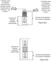
- FIG 2 schematically illustrates the role of confinement of energy intake.
- FIG 2(a) shows a porous substrate crossed by a first gas flow 21 and by a second gas flow 22; these two gas flows mix within a confined zone of the substrate, in a heated enclosure. The substrate heating mode does not generate heating confinement within the substrate.
- FIG 2(b) shows a porous substrate crossed by a single gas flow with a supply of thermal energy located downstream of the porous substrate which only heats the substrate in a thin zone close to its outlet.
- FIG 2(c) shows the same configuration, but with an energy supply confined in a thin zone close to the outlet of the porous substrate.
- FIG 3 schematically shows two embodiments for carrying out localized heating of the substrate by induction: with a metal foam fixed at the outlet of the porous substrate ( figure 4(a) ) and with a metal ring at the outlet of the porous substrate ( figure 3(b) ).
- FIG. 4 schematically shows four partial cross-sectional views of reactors which are suitable for implementing the invention.
- the first gas stream initially comprises the catalyst aerosol, which comprises particles comprising a precursor metal compound of a catalyst, said particles being carried by a carrier gas.
- This carrier gas may comprise a carbon precursor hydrocarbon compound, or it may be inert under the chosen reaction conditions (it may for example be a hydrocarbon compound which does not decompose catalytically under the chosen reaction conditions, or it may can be nitrogen or hydrogen).
- Said particles comprising a precursor metal compound of a catalyst can be produced from a liquid (at the temperature T1 at which said liquid is at the moment it is conveyed into the aerosol forming device) which is composed by said catalyst precursor metal compound, if this compound is a liquid, or by a solution of said catalyst precursor metal compound in a liquid solvent.
- Said liquid solvent may be a carbon precursor hydrocarbon compound, or it may be a compound which is not decomposed under the catalytic decomposition reaction conditions on the porous substrate.
- the catalyst aerosol initially comprises liquid particles.
- the catalyst aerosol can be formed by periodic injection of a liquid phase (being at temperature T1) into a carrier gas.
- a common type injection pump as used in internal combustion engines can be used.
- these liquid particles can evaporate partially or completely; in particular, their solvent can partially or completely evaporate, and the particle forming the catalyst aerosol can become a solid particle consisting of the precursor metal compound of a catalyst, or can evaporate.
- these liquid or solid particles or these gaseous molecules can decompose partially or completely, in particular by pyrolysis, thus releasing the metal catalyst which they contain. .
- Said carbon precursor hydrocarbon compound can be provided by said first gas flow (where it can act as a carrier gas for the aerosol), and/or it can be provided by other gas flows (for example by said second flow gas, and/or a third gas flow).
- Said carbon precursor hydrocarbon compound can also be introduced in the form of an aerosol comprising finely divided liquid particles comprising a carbon precursor hydrocarbon compound (hereinafter called “hydrocarbon aerosol”); in the latter case the hydrocarbon aerosol can be supplied in the same flow as the catalyst aerosol, or by another flow.
- the carbon precursor compound may comprise a single compound or several compounds. These are preferably hydrocarbons, but can also contain, for example, carbon monoxide (CO).
- CO carbon monoxide
- the precursor compound of a metal catalyst is ferrocene. Since ferrocene has a melting point of around 172°C and an evaporation point of around 250°C, it should be dissolved, preferably in toluene.
- the catalyst aerosol therefore comprises droplets of toluene in which ferrocene is dissolved.
- the temperature T1 can be for example between 0°C and 50°C, and advantageously between 15°C and 30°C.
- T2 can be between 120°C and 450°C and preferably between 250°C and 450°C.
- Other solvents can be used, such as benzene or xylene.
- ferrocene has a boiling point (or evaporation) of around 250°C; the inventors do not believe that the exact structure of the particles of the catalyst precursor in the catalyst aerosol is important to the present invention; depending on the conduct of the process, and in particular as a function of the temperatures T1 and T2 it is therefore possible that the catalyst aerosol changes structure between the moment when the catalyst precursor particles are injected into the carrier gas of the first gas flow and the moment where this gas flow arrives on the surface of the porous solid in the zone at temperature T3.
- ferrocene decomposes around 450°C into iron and cyclopentane, and in an advantageous embodiment the temperature T3 is at least equal to 450°C.
- T3 can be between 450°C and 700°C.
- This decomposition of ferrocene can take place in the first gas flow and/or in contact with the porous substrate.
- the catalyst is deposited or formed in the porous substrate or on the porous substrate in the form of nanoparticles.
- a carbon precursor compound capable of being catalytically decomposed by iron nanoparticles formed from ferrocene particles is acetylene; Whether or not the toluene in the catalyst aerosol is also decomposed depends essentially on the temperature.
- Acetylene can be the carrier gas for the catalyst aerosol.
- catalyst precursor for example cobaltocene, nickelocene, or a mixture of ferrocene and/or cobaltocene and/or nickelocene.
- Said catalyst precursor preferably the catalyst aerosol, is carried by a carrier gas and constitutes the first gas flow; this flow is brought into contact with a porous substrate.
- the substrate must have the following characteristics: good resistance to high temperatures, porosity open to reactive gases, good chemical inertness with respect to the reagents, good surface chemical affinity with the catalyst (to ensure adhesion which promotes the growth regime of carbon nanotubes or nanofibers by their base, this growth mechanism being known under the term "base growth mechanism", discussed above), and a low solubility of the catalyst in volume to limit the diffusion and deactivation of the catalytic particle.
- the porous substrate must in particular have sufficient open porosity to be able to be traversed by a gas flow.
- Said porous substrate may be a porous membrane.
- non-metallic substrates which do not conduct electricity can be coated at least partially (and preferably in the region near their exit surface) with a metallic film to reinforce the effect of localized induction heating.
- Bringing the catalyst or catalyst precursor into contact with the porous substrate can be done in several ways.
- the first gas flow (comprising the catalyst precursor compound with its carrier gas) is injected into said porous substrate which it passes through at least partly.
- it is injected near said porous substrate, in particular near its external surface, from the outside.
- said first gas flow be injected into the porous substrate.
- Alternatively II can be injected into the reactor close to the substrate, in particular on its external surface.
- the process according to the invention has the particularity of simultaneously supplying the reaction medium with catalytic nanoparticles and carbon precursor throughout the growth of the nanotubes.
- the supply of the catalyst and the supply of carbon precursor are usually separated into two distinct stages: in a first stage catalytic particles are deposited on the substrate or in the substrate, then in in a second step, the carbon nanotubes are grown by adding a carbon precursor.
- the process according to the invention makes it possible to actually overcome the limitation of the length of the CNTs by disappearance of the catalyst or loss of its catalytic activity: this process makes it possible to permanently replace the catalyst which has become inactive or which has disappeared. by disintegration (that is to say gradually carried into the body of the nanotubes during their growth).
- the process according to the invention leads to carbon nanotubes which contain, spaced apart but present over the entire length of the tubes, nanoparticles of metal catalyst (for example: iron) trapped in the central channel of the nanotube during its growth: this is the signature of this process, resulting from the permanent supply of catalyst in the form of an aerosol, which it shares with the process described in EP 1 515 911 B1 (see Figure III-5 (a) of the thesis, cited above, by Sebastien Lastill, pages 117/118) which proves the permanent contribution of catalyst and its progressive disappearance by incorporation into the nanotubes.
- metal catalyst for example: iron
- the process according to the invention solves a reaction mechanism problem which limits the potential of the processes according to the state of the art: when the length of the VACNT becomes greater than a certain limit ( typically a few hundred micrometers or a few millimeters) the weak diffusion of precursors and by-products (whose flows oppose each other) blocks the access of the precursors to the catalytic sites and the access of the by-products to the surface of the mat of VACNT.
- the catalyst is renewed regularly, and the access of the reactive gases is spatially separated from the release of the by-products.
- a VACNT mat is used as a porous substrate; in a variant we use a VACNT mat whose central channel comprises metal particles (for example Fe or Ni or Co) or metal carbide (for example Fe, Ni or Co carbide) coming from the catalyst manufactured with a contribution continuous catalyst by periodic injection of a catalyst aerosol, knowing that the metal or carbide particles which are found as inclusions in the central channel of the nanotubes make it possible to heat this substrate in a localized manner by induction.
- metal particles for example Fe or Ni or Co
- metal carbide for example Fe, Ni or Co carbide
- a third essential characteristic is that the chemical vapor deposition takes place in a localized zone of the porous substrate, which is preferably located at its downstream periphery (relative to the direction of the carrier gas flow).
- the location of this zone can be defined by the effect of localized heating at a temperature called T3. It is in the heated zone that the catalyst precursor decomposes to form catalyst nanoparticles, and it is in this zone where the catalytic decomposition of the carbon precursor will take place. Depending on the temperature value T3, the decomposition of the catalyst precursor can begin upstream of this zone.
- first gas flow does not contain a carbon precursor compound, or if we want to provide another carbon precursor compound (or an additional quantity of said compound), a second gas flow comprising the carbon precursor compound must be injected as close as possible from this localized area, and preferably in this localized area.
- the injection of said second gas flow countercurrent to said first gas flow should be avoided because it does not allow the secondary reaction products to be easily evacuated.
- the confinement of the catalytic decomposition zone of the carbon precursor compound is an essential aspect of the process according to the invention.
- This confinement can be achieved by two means, which can be combined: by localized heating of the porous substrate to a temperature at least equal to T3, and by localized injection of the flow of carbon precursor compound onto or into the substrate (or an area of said substrate) being at a temperature at least equal to T3.
- this confinement defines the heterogeneous catalysis zone from which the continuous growth of the carbon nanotubes or nanofibers takes place, via their base.
- the location of the energy supply which defines the heterogeneous catalysis zone is the location of the energy supply which defines the heterogeneous catalysis zone.
- Several means of localized heating can be used.
- certain parts of the reaction zone can be selectively heated and/or the porous substrate can participate in the heating (by itself becoming a heated part). This can be achieved for example by inductive heating, using a coil which at least partly surrounds the substrate and by judiciously choosing the materials which constitute the environment of the reaction zone. This is the preferred embodiment.
- the area to be heated is bathed in the oscillating magnetic field generated by a coil which surrounds said area.
- a metal part is positioned in the vicinity of the reaction zone (for example close to the exit surface of the porous substrate), all the other parts located in the zone of influence of the applied magnetic field being either non-metallic or in an electrically conductive material having a lower resistivity than said metal part.
- the porous substrate can be made of a non-metallic material (for example porous alumina), and a metal foam having open macropores can be affixed to the exit surface of the non-metallic porous substrate (or positioned very close to this exit surface).
- the localized energy supply can also be done by any appropriate means, and in particular by resistive heating (Joule effect) of a resistor or of the porous substrate itself, even if these solutions are not the preferred solutions (confinement of heating is more difficult to control, and the connectivity becomes difficult to manage).
- the energy supply can also be done by laser irradiation, but this is not the preferred solution either (because the absorption coefficient of the surfaces can change during the synthesis due to surface deposition, and because space constraints for the optical path of the laser beam must be taken into consideration).
- the porous substrate can also consist of carbon nanotubes, preferably aligned.
- the localized energy supply can also be done by inductive heating of the VACNT, the central channel of which can optionally and advantageously comprise metallic particles or carbides of a metal, as has been explained below. above.
- Localized energy supply can also be done by inductive heating directly of the active catalytic particles for the synthesis of carbon nanotubes.
- This solution is the one which allows the most localized heating. It can be used alone, or preferably in addition to another means of heating, in particular in the case where it alone does not make it possible to constitute the entire energy supply necessary for the growth of the CNTs.
- To these localized heating means can be added a preheating of said first and/or second gas flow.
- the porous substrate can also be provided with a metallic coating so that only its surface is heated by induction (for example an aluminum coating on porous alumina).
- the confinement of the energy supply could also be completed by the insertion of thermal barriers, for example made up of layers with low thermal conductivity close to the reactive zone (outlet surface of the porous substrate).
- the heated substrate is in an enclosure, called here "reactor", and the process advantageously takes place at a pressure close to atmospheric pressure.
- This enclosure can be closed or partially closed but made airtight against gas exchanges between the interior and exterior of the reactor. It includes means for collecting the nanotubes formed.
- the enclosure may include means for heating its walls, in order to avoid excessive thermal gradients within the reactor.
- the reactor also includes pumping means, knowing that the gases entering the reactor as well as the gases resulting from the process must be evacuated continuously.
- the reactor also includes purge means; the purge can be done by rinsing using a neutral gas, associated or not with steaming the reactor prior to starting the process.
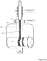
- FIG 4 schematically shows three partial views in cross section of reactors which are suitable for implementing the process according to the invention.
- FIG 4(a) shows the supply conduit 41 with gas mixture 40 (this gas mixture comprising the catalyst precursor and the carbon precursor) with the heating means 42 making it possible to reach a temperature T2 (defined above, for example a heating resistor surrounding the supply conduit), as well as the porous substrate 43 crossed by this gas flow.
- the localized heating means 45 (for example a metal ring heated by an induction coil) making it possible to reach a temperature T3 sufficient to allow the catalytic growth of carbon nanotubes or nanofibers are located very close to the outlet surface 44 of the porous substrate 43.
- a heating zone Downstream of the porous substrate 43 is located, optionally, a heating zone provided with heating means 55 making it possible to heat the nanotubes or nanofibers to a temperature T4 making it possible to improve their crystallinity.
- the condition T2 ⁇ T3 must be met.
- FIG. 4(b) shows the growth of carbon nanotubes or nanofibers 46 which deploy in a tubular deployment zone 49 located downstream of the porous substrate 43. If the reactor includes the heating means 55 making it possible to heat the nanotubes or nanofibers to a temperature T4, these means are advantageously located around this tubular deployment zone 49.
- FIG. 4(c) shows a means 47 for winding the nanotubes or nanofibers.
- the reaction gases having not reacted, the carrier gases and the gaseous reaction products leave the reactor through an evacuation port 48.
- the pressure is advantageously close to the ambient pressure.
- FIG 4(d) shows a variant of the reactor according to the figure 4(c) in which the reactor has means for continuously releasing the nanotubes produced.
- the means 47 for winding the nanotubes or nanofibers can be an endless screw capable of moving the nanotubes or nanofibers laterally in the direction of the arrow.
- the reactor is not completely closed: a slot 52 is provided to allow the exit of the means 47 for winding the nanotubes or nanofibers.
- a nitrogen blade 50 with its suction means 51 is provided to isolate the interior of the reactor from the ambient atmosphere.
- reaction zone the targeted heterogeneous catalysis zone
- the temperature is not sufficiently confined (typically a temperature above 450°C)
- the growth of the CNTs will take place far from the surface of the porous substrate, which will inevitably lead to clogging of the pores and the cessation of the growth of CNTs.
- coaxial injection heads make it possible in particular to confine the reactive gases without mixing them on a scale of a few millimeters; the exit of the injection head can correspond to the entrance surface of the porous substrate.
- FIG. 6 shows an embodiment with coaxial injection (shown in longitudinal section): a first gas flow 21 is injected into the porous reactor substrate 64 through a first peripheral tube 61, at the center of which is a second tube 62 which injects the second flow gas 22.
- the two gas streams mix in the porous substrate 64, and the growth of the carbon nanotubes 66 takes place on the surface of the substrate.
- FIG. 6(a) does not show the means for confined heating ensuring the temperature T4 necessary for the growth of carbon nanotubes.
- FIG 6(b) shows a more complex injection mode derived from that of the figure 6(a) with a coaxial outer tube 61 and inner tube 62 and a coaxial peripheral tube 63 dedicated to the suction of the reactive mixture; the gas flows mix when they are deflected in the suction tube 63.
- a porous substrate is not provided, the growth of the carbon nanotubes takes place on the edges (the edge) of the tube 62 injecting the second gas flow 22 ; the coaxial tubes playing in this case the role of a porous substrate with partitioned porosity.
- a porous substrate is provided, the growth of the carbon nanotubes takes place on or near the exit surface thereof; in this embodiment the porous substrate is advantageously very thin (porous membrane).
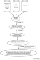
- FIG. 5(a) shows an embodiment with localized heating to the catalytic decomposition temperature of the carbon precursor, by one of the means presented above in section 3.
- the catalyst precursor is dissolved in a liquid solvent. It may be, for example, ferrocene dissolved in toluene.
- An aerosol is formed comprising particles (droplets) of this solution and a gas phase as vector, said gas phase comprising the carbon precursor gas, which is a hydrocarbon, and said gas phase possibly comprising other gases.
- This aerosol is heated to a first temperature T1, sufficient to allow the evaporation of the solvent and the catalyst precursor.
- this gas phase is heated to a second temperature T2, sufficient to allow the decomposition of the catalyst precursor.
- This decomposition probably forms atoms of an appropriate metal element and then metal aggregates.
- the catalyst precursor is ferrocene
- iron atoms are formed. These atoms aggregate and form metal nanoparticles on the surface of the porous substrate. (Note that in the context of the present invention it is not important to know whether the aggregation takes place in the gas phase or on the surface of the substrate).
- T3 a third temperature
- This decomposition leads to the formation of carbon nanotubes by the mechanism of growth from the base, through a continuous supply of carbon freshly generated by the decomposition of the carbon precursor, this supply being made through the porous substrate.
- Fresh catalyst nanoparticles are formed almost continuously, or at least periodically, by continuous supply of metal atoms which agglomerate to form new nanoparticles or which are added to existing nanoparticles, this supply being made through the porous substrate.
- the growth of carbon nanotubes is not normally interrupted, except in the event of an accidental event or instability of the reaction conditions. In this embodiment the condition T1 ⁇ T2 ⁇ T3 must be met.
- FIG 5(b) shows another embodiment with localized supply of the carbon precursor into the reaction zone heated to a temperature T3 sufficient to allow the growth of carbon nanotubes or nanofibers.
- a first gas flow 21 is formed by the catalytic aerosol in a carrier gas (which may be a carbon source gas or, as indicated in the diagram, another gas).
- a second gas flow 22 is formed by a carbon precursor, possibly diluted in another gas.
- the precursor of the catalyst dissolved in the liquid solvent is mixed with another gas to form an aerosol, as in the embodiment of the figure 5(a) , which is heated to a first temperature T1 to evaporate the solvent and the catalyst precursor.
- This gas flow is heated to a second temperature T2, sufficient to allow the decomposition of the catalyst precursor; the metal atoms of said catalyst precursor aggregate and form metal nanoparticles on the surface of the porous substrate.
- the substrate is heated to a third temperature T3 sufficient to allow the growth of carbon nanotubes or nanofibers.
- the second gas flow 22 which comprises a carbon precursor gas, possibly mixed with another gas, is brought into contact with the catalyst located at the outlet surface of the porous substrate by localized supply in the zone heated to said third temperature T3, of so that the catalytic decomposition of said carbon precursor in this zone leads to the formation of carbon nanotubes by the mechanism of growth from the base, through a continuous supply of carbon freshly generated by the decomposition of the precursor of carbon, this contribution being made in a localized manner.
- Fresh catalyst nanoparticles are formed almost continuously, or at least periodically, by continuous supply of metal atoms which agglomerate to form new nanoparticles or which are added to existing nanoparticles, this supply being made through the porous substrate.
- the growth of carbon nanotubes is not normally interrupted, except in the event of an accidental event or instability of the reaction conditions.
- the condition T1 ⁇ T2 ⁇ T3 must be fulfilled.
- a fourth heating zone at a fourth temperature T4 can be planned downstream of the nanotube growth zone, to improve the crystallinity (i.e. the order at the atomic and nanoscale) of the carbon nanotubes or nanofibers formed.
- the process according to the invention makes it possible to form in situ (i.e. on the porous surface of the substrate, and in the reaction zone) catalytic particles from the particles of the catalyst aerosol. ; in fact, these particles of precursor compound of a catalyst decompose by pyrolysis in the localized heated zone of the porous substrate, and form metallic particles of nanometric size.
- the process according to the invention would therefore be characterized by the fact that the supply of reagents is located directly in the vicinity of the catalytic particles, and in the reaction zone.
- a porous substrate is used which can simultaneously play the role of mechanical support, catalyst regenerator and source of carbon precursor.
- the flow of reactive reactants catalyst and carbon precursor
- a permanent supply - evacuation regime can be established, independent of the length of the carbon nanotubes.
- the method according to the invention allows the growth of nanotubes and nanofibers of great length, this growth taking place in the form of a bundle of nanotubes or parallel nanofibers; this facilitates the handling of the nanotubes or nanofibers obtained.
- this tube can be led into a tube by directing the flow of gas leaving the reaction zone towards this tube.
- this tube can be made of metal or quartz, and its end can be located close to the substrate (which can be a collection surface, for example the surface of a rotating roller), which allows to accommodate, direct and protect the bundle of nanotubes or nanofibers obtained.
- nanotubes and nanofibers show a very low number of crystalline interfaces or junctions along their length, or are even free of such interfaces or junctions; these interfaces and junctions can be demonstrated by different analysis techniques known to those skilled in the art, and in any case by transmission electron microscopy.
- Said nanotubes and nanofibers of great length according to the invention can be used as electrical conductors, or in the manufacture of electrical conductors. They can also be used, possibly after coating, as mechanical cables and/or as thermal energy transport elements. In these three applications, their thermal and/or electrical conductivity is improved by the uninterrupted nature of said nanotubes and nanofibers, and by their excellent crystallographic quality.
Landscapes
- Chemical & Material Sciences (AREA)
- Engineering & Computer Science (AREA)
- Materials Engineering (AREA)
- Organic Chemistry (AREA)
- Nanotechnology (AREA)
- Chemical Kinetics & Catalysis (AREA)
- Inorganic Chemistry (AREA)
- Textile Engineering (AREA)
- General Chemical & Material Sciences (AREA)
- Physics & Mathematics (AREA)
- Thermal Sciences (AREA)
- Carbon And Carbon Compounds (AREA)
- Catalysts (AREA)
- Conductive Materials (AREA)
- Manufacturing Of Electric Cables (AREA)
Claims (15)
- Verfahren zur Herstellung eines aus Kohlenstoffnanoröhren gebildeten Kabels, umfassend die Zersetzung mindestens einer Kohlenstoffvorläuferverbindung und mindestens einer Vorläuferverbindung eines Katalysators auf einem porösen Substrat (43, 64), bei welchem Verfahren kontinuierlich:- ein erster Gasstrom (21), der eine Vorstufe eines Katalysators umfasst, mit einem porösen Substrat (43, 64) in Kontakt gebracht wird;- ein zweiter Gasstrom (22), der mindestens einen Kohlenstoffvorläufer umfasst, mit diesem porösen Substrat (43, 64) in Kontakt gebracht wird;- dieses poröse Substrat (43) auf eine Temperatur erhitzt wird, die zur Ablagerung von Katalysatorpartikeln und zum katalytischen Wachstum eines Bündels von KohlenstoffNanoröhren führt, vorzugsweise zwischen 500°C und 1000°C.
- Verfahren nach Anspruch 1, bei dem dieses poröse Substrat (43, 64) zumindest teilweise von diesem ersten Gasstrom (21) durchquert wird.
- Verfahren nach Anspruch 1, bei dem dieser erste Gasstrom (21) auf einen Oberflächenbereich dieses porösen Substrats (43, 64) gerichtet wird.
- Verfahren nach Anspruch 2 oder Anspruch 3, bei dem dieses poröse Substrat (43, 64) in einer Zone nahe der Zone, durch die dieser erste Gasstrom (21) das Substrat (43, 64) verlässt, oder nahe der Zone, auf welche dieser erste Gasstrom (21) gerichtet ist, erhitzt wird.
- Verfahren nach einem der Ansprüche 1 bis 4, dadurch gekennzeichnet, dass der Kohlenstoffvorläufer ein Kohlenwasserstoff und/oder Kohlenmonoxid ist.
- Verfahren nach einem der Ansprüche 1 bis 5, dadurch gekennzeichnet, dass die örtliche Erwärmung durch elektromagnetische Induktion erfolgt.
- Verfahren nach Anspruch 6, dadurch gekennzeichnet, dass die örtliche Erwärmung zumindest teilweise durch induktive Erwärmung der Katalysatorpartikel erfolgt.
- Verfahren nach einem der Ansprüche 1 bis 7, dadurch gekennzeichnet, dass das poröse Substrat (43, 64) aus der Gruppe ausgewählt wird, die gebildet wird durch: poröses Silizium, poröses Aluminiumoxid, poröses Siliziumkarbid, Metallschäume mit miteinander verbundenen Poren, Kohlenstoffschäume mit miteinander verbundenen Poren, vertikal ausgerichtete Kohlenstoffnanoröhren, Mischsubstrate bestehend aus mehreren der oben genannten Substrate.
- Verfahren nach einem der Ansprüche 1 bis 8, das außerdem einen Schritt umfasst, in dem das Bündel von Nanoröhren über eine gewünschte Länge mit einem Metall, wie etwa Kupfer, beschichtet wird.
- Verfahren nach Anspruch 9, dadurch gekennzeichnet, dass das Nanoröhrenbündel an einem seiner Enden mit einem Metall beschichtet wird, und dadurch, dass diese Metallbeschichtung mit einem elektrischen Verbindungselement in Kontakt gebracht wird
- Verfahren nach einem der Ansprüche 1 bis 10, das außerdem einen Schritt umfasst, in dem dieses Nanoröhrenbündel mit einem elektrisch isolierenden Material beschichtet wird.
- Aus Kohlenstoffnanoröhren gebildetes Kabel, das nach dem Verfahren nach einem der Ansprüche 9 bis 11 hergestellt werden kann.
- Elektrisches Verbindungselement, dadurch gekennzeichnet, dass es ein Kabel nach Anspruch 12 umfasst.
- Reaktor zur Durchführung des Verfahrens nach einem der Ansprüche 1 bis 11, umfassend in Strömungsrichtung des Gasstroms:- Mittel zum Zuführen eines ersten reaktiven Gasstroms, der einen Vorläufer eines Katalysators umfasst, und eines zweiten reaktiven Gasstroms, der mindestens einen Kohlenstoff-Vorläufer umfasst,- eine Zone zum Einspritzen eines reaktiven Gasstroms, die mit ersten Heizmitteln (42) ausgestattet ist, die in der Lage sind, die Gase auf eine Temperatur T2 zwischen 250 °C und 450 °C zu erhitzen,- ein poröses Substrat (43), das von diesem reaktiven Gasstrom durchströmt wird,- eine Zone, die mit zweiten Heizmitteln (45) ausgestattet ist, die in der Lage sind, mindestens einen Teil des porösen Substrats (43) auf eine Temperatur T3 zwischen 450°C und 700°C zu erhitzen, wobei diese zweiten Heizmittel lokalisierte Heizmittel sind, und bevorzugt Induktionsheizmittel sind,- eine röhrenförmige Entfaltungszone (49), die die Entfaltung der gebildeten Nanofasern oder Nanoröhrchen ermöglichen kann,- Mittel (47) zum Sammeln dieser Nanofasern oder Nanoröhrchen;- einen Auslass (48), durch den die Gase den Reaktor verlassen können.
- Reaktor nach Anspruch 14, dadurch gekennzeichnet, dass er Mittel zum Eingrenzen der katalytischen Zersetzungszone des Kohlenstoffvorläufers umfasst.
Applications Claiming Priority (2)
| Application Number | Priority Date | Filing Date | Title |
|---|---|---|---|
| FR1755819A FR3068029B1 (fr) | 2017-06-26 | 2017-06-26 | Procede de fabrication de cables en nanotubes de carbone alignes |
| PCT/FR2018/051475 WO2019002722A1 (fr) | 2017-06-26 | 2018-06-20 | Procede de fabrication de cables en nanotubes de carbone alignes |
Publications (3)
| Publication Number | Publication Date |
|---|---|
| EP3645461A1 EP3645461A1 (de) | 2020-05-06 |
| EP3645461C0 EP3645461C0 (de) | 2024-01-24 |
| EP3645461B1 true EP3645461B1 (de) | 2024-01-24 |
Family
ID=60765687
Family Applications (1)
| Application Number | Title | Priority Date | Filing Date |
|---|---|---|---|
| EP18737693.4A Active EP3645461B1 (de) | 2017-06-26 | 2018-06-20 | Verfahren zur herstellung von kabeln, die aus ausgerichteten kohlenstoffnanoröhrchen gefertigt sind |
Country Status (6)
| Country | Link |
|---|---|
| US (1) | US11401628B2 (de) |
| EP (1) | EP3645461B1 (de) |
| JP (1) | JP7121115B2 (de) |
| CN (1) | CN111094179B (de) |
| FR (1) | FR3068029B1 (de) |
| WO (1) | WO2019002722A1 (de) |
Families Citing this family (3)
| Publication number | Priority date | Publication date | Assignee | Title |
|---|---|---|---|---|
| MY207629A (en) * | 2019-07-11 | 2025-03-06 | Petroliam Nasional Berhad Petronas | A reactor and method for making calcium hydroxide |
| WO2022140416A1 (en) * | 2020-12-22 | 2022-06-30 | Nanocomp Technologies, Inc. | Two-stage system and method for producing carbon nanotubes |
| CN115611268B (zh) * | 2022-11-02 | 2025-06-24 | 清华大学 | 一种超长碳纳米管的超高产率制备方法 |
Family Cites Families (13)
| Publication number | Priority date | Publication date | Assignee | Title |
|---|---|---|---|---|
| FR2841233B1 (fr) * | 2002-06-24 | 2004-07-30 | Commissariat Energie Atomique | Procede et dispositif de depot par pyrolyse de nanotubes de carbone |
| US7431965B2 (en) * | 2002-11-01 | 2008-10-07 | Honda Motor Co., Ltd. | Continuous growth of single-wall carbon nanotubes using chemical vapor deposition |
| GB0316367D0 (en) * | 2003-07-11 | 2003-08-13 | Univ Cambridge Tech | Production of agglomerates from gas phase |
| WO2005044723A2 (en) | 2003-10-16 | 2005-05-19 | The University Of Akron | Carbon nanotubes on carbon nanofiber substrate |
| WO2005098084A2 (en) * | 2004-01-15 | 2005-10-20 | Nanocomp Technologies, Inc. | Systems and methods for synthesis of extended length nanostructures |
| JP2005263564A (ja) | 2004-03-19 | 2005-09-29 | Toyota Central Res & Dev Lab Inc | カーボンナノチューブの製造方法 |
| WO2007009112A2 (en) * | 2005-07-14 | 2007-01-18 | Colorado School Of Mines | Membrane separation of feed and growth environments in carbon nanostructure growth |
| US7850778B2 (en) | 2005-09-06 | 2010-12-14 | Lemaire Charles A | Apparatus and method for growing fullerene nanotube forests, and forming nanotube films, threads and composite structures therefrom |
| US7714798B2 (en) * | 2005-11-04 | 2010-05-11 | Nanocomp Technologies, Inc. | Nanostructured antennas and methods of manufacturing same |
| CN101499337B (zh) * | 2008-02-01 | 2013-01-09 | 清华大学 | 线缆的制造方法 |
| RU2497752C2 (ru) * | 2011-11-29 | 2013-11-10 | Инфра Текнолоджис Лтд. | Способ получения длинных углеродных нанотрубок и устройство для осуществления этого способа |
| WO2014202740A1 (en) * | 2013-06-19 | 2014-12-24 | Katholieke Universiteit Leuven | Systems and methods for synthesis of carbon nanotubes |
| US10273599B2 (en) * | 2015-07-24 | 2019-04-30 | Lg Chem, Ltd. | Apparatus for manufacturing carbon nanotube fiber |
-
2017
- 2017-06-26 FR FR1755819A patent/FR3068029B1/fr not_active Expired - Fee Related
-
2018
- 2018-06-20 JP JP2020520728A patent/JP7121115B2/ja active Active
- 2018-06-20 CN CN201880042956.4A patent/CN111094179B/zh active Active
- 2018-06-20 US US16/626,024 patent/US11401628B2/en active Active
- 2018-06-20 EP EP18737693.4A patent/EP3645461B1/de active Active
- 2018-06-20 WO PCT/FR2018/051475 patent/WO2019002722A1/fr not_active Ceased
Non-Patent Citations (1)
| Title |
|---|
| ZHANG Y ET AL: "Metal coating on suspended carbon nanotubes and its implication to metal-tube interaction", CHEMICAL PHYSICS LETTERS, ELSEVIER BV, NL, vol. 331, 24 November 2000 (2000-11-24), pages 35 - 41, XP002530276, ISSN: 0009-2614, DOI: 10.1016/S0009-2614(00)01162-3 * |
Also Published As
| Publication number | Publication date |
|---|---|
| WO2019002722A1 (fr) | 2019-01-03 |
| CN111094179A (zh) | 2020-05-01 |
| CN111094179B (zh) | 2023-06-13 |
| FR3068029B1 (fr) | 2022-12-16 |
| EP3645461A1 (de) | 2020-05-06 |
| US20200149195A1 (en) | 2020-05-14 |
| EP3645461C0 (de) | 2024-01-24 |
| FR3068029A1 (fr) | 2018-12-28 |
| US11401628B2 (en) | 2022-08-02 |
| JP2020525400A (ja) | 2020-08-27 |
| JP7121115B2 (ja) | 2022-08-17 |
Similar Documents
| Publication | Publication Date | Title |
|---|---|---|
| EP2254830B1 (de) | Wachstum von kohlenstoffnanoröhren auf kohlenstoff- oder metallsubstraten | |
| FR2939422A1 (fr) | Procede de synthese de nanotubes de carbone sur materiaux micrometriques longs et particulaires | |
| EP3645461B1 (de) | Verfahren zur herstellung von kabeln, die aus ausgerichteten kohlenstoffnanoröhrchen gefertigt sind | |
| EP1713959A2 (de) | Verfahren zur herstellung von kohlenstoffnanoröhren auf trägern und verbundwerkstoffe damit | |
| FR2841233A1 (fr) | Procede et dispositif de depot par pyrolyse de nanotubes de carbone | |
| EP2144698A2 (de) | Komposit aus nanoröhrchen oder nanofasern auf einem b-sic-film | |
| WO2008029927A1 (en) | Method for production of carbon nanotube | |
| EP3645460B1 (de) | Verfahren zur herstellung von an einem substrat befestigten kohlenstoffnanoröhrchen | |
| EP2467205A2 (de) | Zweilagiger katalysator, herstellungsverfahren dafür und verwendung für die herstellung von nanoröhren | |
| JP2022508630A (ja) | カーボンナノチューブを含むヤーンの製造方法、これから製造されたヤーン | |
| US20140194658A1 (en) | New Class Of Tunable Gas Storage And Sensor Materials | |
| WO2016207134A1 (fr) | Matériau biphasique à base de silice et de nanotubes de carbone | |
| EP2788288B1 (de) | Verbessertes verfahren zur herstellung von kohlenstoffnanoröhrchen auf mehreren trägern | |
| RU2546154C1 (ru) | Нанокомпозит на основе азотосодержащих углеродных нанотрубок с инкапсулированными частицами кобальта и никеля и способ его получения | |
| WO2014128250A1 (fr) | Procédé de fabrication d'un nanotube de carbone multi-parois; nanotube, source d'électrons et dispositif associés | |
| Han et al. | 3-Orders-of-magnitude density control of single-walled carbon nanotube networks by maximizing catalyst activation and dosing carbon supply | |
| Zhang et al. | Synthesis of Core‐Shell SiOx/Carbon Nanofibers on Silicon Substrates by Ultrasonic Spray Pyrolysis | |
| JP2010163334A (ja) | カーボンナノチューブの製造方法 | |
| FR2879627A1 (fr) | Procede de croissance de nanofils de beta-sic ou de alpha-si3n4, eventuellement enrobes | |
| Manocha et al. | Role of metal catalyst and substrate site for the growth of carbon nanomaterials | |
| McJilton | Controlled synthesis of single-walled carbon nanotubes |
Legal Events
| Date | Code | Title | Description |
|---|---|---|---|
| STAA | Information on the status of an ep patent application or granted ep patent |
Free format text: STATUS: UNKNOWN |
|
| STAA | Information on the status of an ep patent application or granted ep patent |
Free format text: STATUS: THE INTERNATIONAL PUBLICATION HAS BEEN MADE |
|
| PUAI | Public reference made under article 153(3) epc to a published international application that has entered the european phase |
Free format text: ORIGINAL CODE: 0009012 |
|
| STAA | Information on the status of an ep patent application or granted ep patent |
Free format text: STATUS: REQUEST FOR EXAMINATION WAS MADE |
|
| 17P | Request for examination filed |
Effective date: 20200127 |
|
| AK | Designated contracting states |
Kind code of ref document: A1 Designated state(s): AL AT BE BG CH CY CZ DE DK EE ES FI FR GB GR HR HU IE IS IT LI LT LU LV MC MK MT NL NO PL PT RO RS SE SI SK SM TR |
|
| AX | Request for extension of the european patent |
Extension state: BA ME |
|
| DAV | Request for validation of the european patent (deleted) | ||
| DAX | Request for extension of the european patent (deleted) | ||
| GRAP | Despatch of communication of intention to grant a patent |
Free format text: ORIGINAL CODE: EPIDOSNIGR1 |
|
| STAA | Information on the status of an ep patent application or granted ep patent |
Free format text: STATUS: GRANT OF PATENT IS INTENDED |
|
| INTG | Intention to grant announced |
Effective date: 20230906 |
|
| GRAS | Grant fee paid |
Free format text: ORIGINAL CODE: EPIDOSNIGR3 |
|
| GRAA | (expected) grant |
Free format text: ORIGINAL CODE: 0009210 |
|
| STAA | Information on the status of an ep patent application or granted ep patent |
Free format text: STATUS: THE PATENT HAS BEEN GRANTED |
|
| AK | Designated contracting states |
Kind code of ref document: B1 Designated state(s): AL AT BE BG CH CY CZ DE DK EE ES FI FR GB GR HR HU IE IS IT LI LT LU LV MC MK MT NL NO PL PT RO RS SE SI SK SM TR |
|
| REG | Reference to a national code |
Ref country code: GB Ref legal event code: FG4D Free format text: NOT ENGLISH |
|
| REG | Reference to a national code |
Ref country code: CH Ref legal event code: EP |
|
| REG | Reference to a national code |
Ref country code: DE Ref legal event code: R096 Ref document number: 602018064486 Country of ref document: DE |
|
| REG | Reference to a national code |
Ref country code: IE Ref legal event code: FG4D Free format text: LANGUAGE OF EP DOCUMENT: FRENCH |
|
| U01 | Request for unitary effect filed |
Effective date: 20240208 |
|
| U07 | Unitary effect registered |
Designated state(s): AT BE BG DE DK EE FI FR IT LT LU LV MT NL PT SE SI Effective date: 20240216 |
|
| PG25 | Lapsed in a contracting state [announced via postgrant information from national office to epo] |
Ref country code: IS Free format text: LAPSE BECAUSE OF FAILURE TO SUBMIT A TRANSLATION OF THE DESCRIPTION OR TO PAY THE FEE WITHIN THE PRESCRIBED TIME-LIMIT Effective date: 20240524 |
|
| PGFP | Annual fee paid to national office [announced via postgrant information from national office to epo] |
Ref country code: GB Payment date: 20240619 Year of fee payment: 7 |
|
| PG25 | Lapsed in a contracting state [announced via postgrant information from national office to epo] |
Ref country code: GR Free format text: LAPSE BECAUSE OF FAILURE TO SUBMIT A TRANSLATION OF THE DESCRIPTION OR TO PAY THE FEE WITHIN THE PRESCRIBED TIME-LIMIT Effective date: 20240425 |
|
| PG25 | Lapsed in a contracting state [announced via postgrant information from national office to epo] |
Ref country code: RS Free format text: LAPSE BECAUSE OF FAILURE TO SUBMIT A TRANSLATION OF THE DESCRIPTION OR TO PAY THE FEE WITHIN THE PRESCRIBED TIME-LIMIT Effective date: 20240424 Ref country code: HR Free format text: LAPSE BECAUSE OF FAILURE TO SUBMIT A TRANSLATION OF THE DESCRIPTION OR TO PAY THE FEE WITHIN THE PRESCRIBED TIME-LIMIT Effective date: 20240124 |
|
| PG25 | Lapsed in a contracting state [announced via postgrant information from national office to epo] |
Ref country code: ES Free format text: LAPSE BECAUSE OF FAILURE TO SUBMIT A TRANSLATION OF THE DESCRIPTION OR TO PAY THE FEE WITHIN THE PRESCRIBED TIME-LIMIT Effective date: 20240124 |
|
| PG25 | Lapsed in a contracting state [announced via postgrant information from national office to epo] |
Ref country code: RS Free format text: LAPSE BECAUSE OF FAILURE TO SUBMIT A TRANSLATION OF THE DESCRIPTION OR TO PAY THE FEE WITHIN THE PRESCRIBED TIME-LIMIT Effective date: 20240424 Ref country code: NO Free format text: LAPSE BECAUSE OF FAILURE TO SUBMIT A TRANSLATION OF THE DESCRIPTION OR TO PAY THE FEE WITHIN THE PRESCRIBED TIME-LIMIT Effective date: 20240424 Ref country code: IS Free format text: LAPSE BECAUSE OF FAILURE TO SUBMIT A TRANSLATION OF THE DESCRIPTION OR TO PAY THE FEE WITHIN THE PRESCRIBED TIME-LIMIT Effective date: 20240524 Ref country code: HR Free format text: LAPSE BECAUSE OF FAILURE TO SUBMIT A TRANSLATION OF THE DESCRIPTION OR TO PAY THE FEE WITHIN THE PRESCRIBED TIME-LIMIT Effective date: 20240124 Ref country code: GR Free format text: LAPSE BECAUSE OF FAILURE TO SUBMIT A TRANSLATION OF THE DESCRIPTION OR TO PAY THE FEE WITHIN THE PRESCRIBED TIME-LIMIT Effective date: 20240425 Ref country code: ES Free format text: LAPSE BECAUSE OF FAILURE TO SUBMIT A TRANSLATION OF THE DESCRIPTION OR TO PAY THE FEE WITHIN THE PRESCRIBED TIME-LIMIT Effective date: 20240124 |
|
| PG25 | Lapsed in a contracting state [announced via postgrant information from national office to epo] |
Ref country code: PL Free format text: LAPSE BECAUSE OF FAILURE TO SUBMIT A TRANSLATION OF THE DESCRIPTION OR TO PAY THE FEE WITHIN THE PRESCRIBED TIME-LIMIT Effective date: 20240124 |
|
| U20 | Renewal fee for the european patent with unitary effect paid |
Year of fee payment: 7 Effective date: 20240701 |
|
| PG25 | Lapsed in a contracting state [announced via postgrant information from national office to epo] |
Ref country code: PL Free format text: LAPSE BECAUSE OF FAILURE TO SUBMIT A TRANSLATION OF THE DESCRIPTION OR TO PAY THE FEE WITHIN THE PRESCRIBED TIME-LIMIT Effective date: 20240124 |
|
| PG25 | Lapsed in a contracting state [announced via postgrant information from national office to epo] |
Ref country code: SM Free format text: LAPSE BECAUSE OF FAILURE TO SUBMIT A TRANSLATION OF THE DESCRIPTION OR TO PAY THE FEE WITHIN THE PRESCRIBED TIME-LIMIT Effective date: 20240124 |
|
| PGFP | Annual fee paid to national office [announced via postgrant information from national office to epo] |
Ref country code: CH Payment date: 20240704 Year of fee payment: 7 |
|
| PG25 | Lapsed in a contracting state [announced via postgrant information from national office to epo] |
Ref country code: CZ Free format text: LAPSE BECAUSE OF FAILURE TO SUBMIT A TRANSLATION OF THE DESCRIPTION OR TO PAY THE FEE WITHIN THE PRESCRIBED TIME-LIMIT Effective date: 20240124 |
|
| REG | Reference to a national code |
Ref country code: DE Ref legal event code: R097 Ref document number: 602018064486 Country of ref document: DE |
|
| PG25 | Lapsed in a contracting state [announced via postgrant information from national office to epo] |
Ref country code: SK Free format text: LAPSE BECAUSE OF FAILURE TO SUBMIT A TRANSLATION OF THE DESCRIPTION OR TO PAY THE FEE WITHIN THE PRESCRIBED TIME-LIMIT Effective date: 20240124 |
|
| PG25 | Lapsed in a contracting state [announced via postgrant information from national office to epo] |
Ref country code: SM Free format text: LAPSE BECAUSE OF FAILURE TO SUBMIT A TRANSLATION OF THE DESCRIPTION OR TO PAY THE FEE WITHIN THE PRESCRIBED TIME-LIMIT Effective date: 20240124 Ref country code: SK Free format text: LAPSE BECAUSE OF FAILURE TO SUBMIT A TRANSLATION OF THE DESCRIPTION OR TO PAY THE FEE WITHIN THE PRESCRIBED TIME-LIMIT Effective date: 20240124 Ref country code: RO Free format text: LAPSE BECAUSE OF FAILURE TO SUBMIT A TRANSLATION OF THE DESCRIPTION OR TO PAY THE FEE WITHIN THE PRESCRIBED TIME-LIMIT Effective date: 20240124 Ref country code: CZ Free format text: LAPSE BECAUSE OF FAILURE TO SUBMIT A TRANSLATION OF THE DESCRIPTION OR TO PAY THE FEE WITHIN THE PRESCRIBED TIME-LIMIT Effective date: 20240124 |
|
| U1N | Appointed representative for the unitary patent procedure changed after the registration of the unitary effect |
Representative=s name: IXAS CONSEIL; FR |
|
| PLBE | No opposition filed within time limit |
Free format text: ORIGINAL CODE: 0009261 |
|
| STAA | Information on the status of an ep patent application or granted ep patent |
Free format text: STATUS: NO OPPOSITION FILED WITHIN TIME LIMIT |
|
| 26N | No opposition filed |
Effective date: 20241025 |
|
| PG25 | Lapsed in a contracting state [announced via postgrant information from national office to epo] |
Ref country code: MC Free format text: LAPSE BECAUSE OF FAILURE TO SUBMIT A TRANSLATION OF THE DESCRIPTION OR TO PAY THE FEE WITHIN THE PRESCRIBED TIME-LIMIT Effective date: 20240124 |
|
| PG25 | Lapsed in a contracting state [announced via postgrant information from national office to epo] |
Ref country code: IE Free format text: LAPSE BECAUSE OF NON-PAYMENT OF DUE FEES Effective date: 20240620 |
|
| U1K | Transfer of rights of the unitary patent after the registration of the unitary effect |
Owner name: NAWAH; FR |
|
| PG25 | Lapsed in a contracting state [announced via postgrant information from national office to epo] |
Ref country code: CY Free format text: LAPSE BECAUSE OF FAILURE TO SUBMIT A TRANSLATION OF THE DESCRIPTION OR TO PAY THE FEE WITHIN THE PRESCRIBED TIME-LIMIT; INVALID AB INITIO Effective date: 20180620 |
|
| REG | Reference to a national code |
Ref country code: CH Ref legal event code: H13 Free format text: ST27 STATUS EVENT CODE: U-0-0-H10-H13 (AS PROVIDED BY THE NATIONAL OFFICE) Effective date: 20260127 |
|
| GBPC | Gb: european patent ceased through non-payment of renewal fee |
Effective date: 20250620 |
|
| U90 | Renewal fees not paid: noting of loss of rights |
Free format text: RENEWAL FEE NOT PAID FOR YEAR 08 Effective date: 20260128 |
|
| PG25 | Lapsed in a contracting state [announced via postgrant information from national office to epo] |
Ref country code: HU Free format text: LAPSE BECAUSE OF FAILURE TO SUBMIT A TRANSLATION OF THE DESCRIPTION OR TO PAY THE FEE WITHIN THE PRESCRIBED TIME-LIMIT; INVALID AB INITIO Effective date: 20180620 |
|
| PG25 | Lapsed in a contracting state [announced via postgrant information from national office to epo] |
Ref country code: GB Free format text: LAPSE BECAUSE OF NON-PAYMENT OF DUE FEES Effective date: 20250620 |
|
| PG25 | Lapsed in a contracting state [announced via postgrant information from national office to epo] |
Ref country code: CH Free format text: LAPSE BECAUSE OF NON-PAYMENT OF DUE FEES Effective date: 20250630 |