EP1515871B1 - Staufach für ein fahrzeug - Google Patents
Staufach für ein fahrzeug Download PDFInfo
- Publication number
- EP1515871B1 EP1515871B1 EP03732432A EP03732432A EP1515871B1 EP 1515871 B1 EP1515871 B1 EP 1515871B1 EP 03732432 A EP03732432 A EP 03732432A EP 03732432 A EP03732432 A EP 03732432A EP 1515871 B1 EP1515871 B1 EP 1515871B1
- Authority
- EP
- European Patent Office
- Prior art keywords
- storage compartment
- rotation
- axis
- compartment cover
- energy store
- Prior art date
- Legal status (The legal status is an assumption and is not a legal conclusion. Google has not performed a legal analysis and makes no representation as to the accuracy of the status listed.)
- Expired - Lifetime
Links
- 238000013016 damping Methods 0.000 claims description 3
- 238000000151 deposition Methods 0.000 claims 5
- 230000000903 blocking effect Effects 0.000 claims 1
- 238000004146 energy storage Methods 0.000 description 33
- 230000005540 biological transmission Effects 0.000 description 3
- 238000006073 displacement reaction Methods 0.000 description 1
- 239000004744 fabric Substances 0.000 description 1
- 238000002955 isolation Methods 0.000 description 1
- 239000010985 leather Substances 0.000 description 1
- 238000012986 modification Methods 0.000 description 1
- 230000004048 modification Effects 0.000 description 1
- 239000002023 wood Substances 0.000 description 1
Images


Classifications
-
- E—FIXED CONSTRUCTIONS
- E05—LOCKS; KEYS; WINDOW OR DOOR FITTINGS; SAFES
- E05F—DEVICES FOR MOVING WINGS INTO OPEN OR CLOSED POSITION; CHECKS FOR WINGS; WING FITTINGS NOT OTHERWISE PROVIDED FOR, CONCERNED WITH THE FUNCTIONING OF THE WING
- E05F1/00—Closers or openers for wings, not otherwise provided for in this subclass
- E05F1/08—Closers or openers for wings, not otherwise provided for in this subclass spring-actuated, e.g. for horizontally sliding wings
- E05F1/10—Closers or openers for wings, not otherwise provided for in this subclass spring-actuated, e.g. for horizontally sliding wings for swinging wings, e.g. counterbalance
- E05F1/1041—Closers or openers for wings, not otherwise provided for in this subclass spring-actuated, e.g. for horizontally sliding wings for swinging wings, e.g. counterbalance with a coil spring perpendicular to the pivot axis
- E05F1/105—Closers or openers for wings, not otherwise provided for in this subclass spring-actuated, e.g. for horizontally sliding wings for swinging wings, e.g. counterbalance with a coil spring perpendicular to the pivot axis with a compression spring
- E05F1/1058—Closers or openers for wings, not otherwise provided for in this subclass spring-actuated, e.g. for horizontally sliding wings for swinging wings, e.g. counterbalance with a coil spring perpendicular to the pivot axis with a compression spring for counterbalancing
-
- B—PERFORMING OPERATIONS; TRANSPORTING
- B60—VEHICLES IN GENERAL
- B60R—VEHICLES, VEHICLE FITTINGS, OR VEHICLE PARTS, NOT OTHERWISE PROVIDED FOR
- B60R7/00—Stowing or holding appliances inside vehicle primarily intended for personal property smaller than suit-cases, e.g. travelling articles, or maps
- B60R7/04—Stowing or holding appliances inside vehicle primarily intended for personal property smaller than suit-cases, e.g. travelling articles, or maps in driver or passenger space, e.g. using racks
-
- E—FIXED CONSTRUCTIONS
- E05—LOCKS; KEYS; WINDOW OR DOOR FITTINGS; SAFES
- E05B—LOCKS; ACCESSORIES THEREFOR; HANDCUFFS
- E05B83/00—Vehicle locks specially adapted for particular types of wing or vehicle
- E05B83/28—Locks for glove compartments, console boxes, fuel inlet covers or the like
- E05B83/32—Locks for glove compartments, console boxes, fuel inlet covers or the like for console boxes, e.g. between passenger seats
-
- E—FIXED CONSTRUCTIONS
- E05—LOCKS; KEYS; WINDOW OR DOOR FITTINGS; SAFES
- E05D—HINGES OR SUSPENSION DEVICES FOR DOORS, WINDOWS OR WINGS
- E05D15/00—Suspension arrangements for wings
- E05D15/48—Suspension arrangements for wings allowing alternative movements
- E05D15/50—Suspension arrangements for wings allowing alternative movements for opening at either of two opposite edges
- E05D15/502—Suspension arrangements for wings allowing alternative movements for opening at either of two opposite edges by axial separation of the hinge parts at the hinge axis
-
- E—FIXED CONSTRUCTIONS
- E05—LOCKS; KEYS; WINDOW OR DOOR FITTINGS; SAFES
- E05F—DEVICES FOR MOVING WINGS INTO OPEN OR CLOSED POSITION; CHECKS FOR WINGS; WING FITTINGS NOT OTHERWISE PROVIDED FOR, CONCERNED WITH THE FUNCTIONING OF THE WING
- E05F1/00—Closers or openers for wings, not otherwise provided for in this subclass
- E05F1/08—Closers or openers for wings, not otherwise provided for in this subclass spring-actuated, e.g. for horizontally sliding wings
- E05F1/10—Closers or openers for wings, not otherwise provided for in this subclass spring-actuated, e.g. for horizontally sliding wings for swinging wings, e.g. counterbalance
- E05F1/12—Mechanisms in the shape of hinges or pivots, operated by springs
- E05F1/1246—Mechanisms in the shape of hinges or pivots, operated by springs with a coil spring perpendicular to the pivot axis
- E05F1/1253—Mechanisms in the shape of hinges or pivots, operated by springs with a coil spring perpendicular to the pivot axis with a compression spring
- E05F1/1261—Mechanisms in the shape of hinges or pivots, operated by springs with a coil spring perpendicular to the pivot axis with a compression spring for counterbalancing
-
- E—FIXED CONSTRUCTIONS
- E05—LOCKS; KEYS; WINDOW OR DOOR FITTINGS; SAFES
- E05F—DEVICES FOR MOVING WINGS INTO OPEN OR CLOSED POSITION; CHECKS FOR WINGS; WING FITTINGS NOT OTHERWISE PROVIDED FOR, CONCERNED WITH THE FUNCTIONING OF THE WING
- E05F1/00—Closers or openers for wings, not otherwise provided for in this subclass
- E05F1/08—Closers or openers for wings, not otherwise provided for in this subclass spring-actuated, e.g. for horizontally sliding wings
- E05F1/10—Closers or openers for wings, not otherwise provided for in this subclass spring-actuated, e.g. for horizontally sliding wings for swinging wings, e.g. counterbalance
- E05F1/1041—Closers or openers for wings, not otherwise provided for in this subclass spring-actuated, e.g. for horizontally sliding wings for swinging wings, e.g. counterbalance with a coil spring perpendicular to the pivot axis
- E05F1/1066—Closers or openers for wings, not otherwise provided for in this subclass spring-actuated, e.g. for horizontally sliding wings for swinging wings, e.g. counterbalance with a coil spring perpendicular to the pivot axis with a traction spring
- E05F1/1075—Closers or openers for wings, not otherwise provided for in this subclass spring-actuated, e.g. for horizontally sliding wings for swinging wings, e.g. counterbalance with a coil spring perpendicular to the pivot axis with a traction spring for counterbalancing
-
- E—FIXED CONSTRUCTIONS
- E05—LOCKS; KEYS; WINDOW OR DOOR FITTINGS; SAFES
- E05F—DEVICES FOR MOVING WINGS INTO OPEN OR CLOSED POSITION; CHECKS FOR WINGS; WING FITTINGS NOT OTHERWISE PROVIDED FOR, CONCERNED WITH THE FUNCTIONING OF THE WING
- E05F1/00—Closers or openers for wings, not otherwise provided for in this subclass
- E05F1/08—Closers or openers for wings, not otherwise provided for in this subclass spring-actuated, e.g. for horizontally sliding wings
- E05F1/10—Closers or openers for wings, not otherwise provided for in this subclass spring-actuated, e.g. for horizontally sliding wings for swinging wings, e.g. counterbalance
- E05F1/12—Mechanisms in the shape of hinges or pivots, operated by springs
- E05F1/1246—Mechanisms in the shape of hinges or pivots, operated by springs with a coil spring perpendicular to the pivot axis
- E05F1/1269—Mechanisms in the shape of hinges or pivots, operated by springs with a coil spring perpendicular to the pivot axis with a traction spring
- E05F1/1276—Mechanisms in the shape of hinges or pivots, operated by springs with a coil spring perpendicular to the pivot axis with a traction spring for counterbalancing
-
- E—FIXED CONSTRUCTIONS
- E05—LOCKS; KEYS; WINDOW OR DOOR FITTINGS; SAFES
- E05F—DEVICES FOR MOVING WINGS INTO OPEN OR CLOSED POSITION; CHECKS FOR WINGS; WING FITTINGS NOT OTHERWISE PROVIDED FOR, CONCERNED WITH THE FUNCTIONING OF THE WING
- E05F5/00—Braking devices, e.g. checks; Stops; Buffers
-
- E—FIXED CONSTRUCTIONS
- E05—LOCKS; KEYS; WINDOW OR DOOR FITTINGS; SAFES
- E05Y—INDEXING SCHEME ASSOCIATED WITH SUBCLASSES E05D AND E05F, RELATING TO CONSTRUCTION ELEMENTS, ELECTRIC CONTROL, POWER SUPPLY, POWER SIGNAL OR TRANSMISSION, USER INTERFACES, MOUNTING OR COUPLING, DETAILS, ACCESSORIES, AUXILIARY OPERATIONS NOT OTHERWISE PROVIDED FOR, APPLICATION THEREOF
- E05Y2201/00—Constructional elements; Accessories therefor
- E05Y2201/40—Motors; Magnets; Springs; Weights; Accessories therefor
- E05Y2201/47—Springs
- E05Y2201/478—Gas springs
-
- E—FIXED CONSTRUCTIONS
- E05—LOCKS; KEYS; WINDOW OR DOOR FITTINGS; SAFES
- E05Y—INDEXING SCHEME ASSOCIATED WITH SUBCLASSES E05D AND E05F, RELATING TO CONSTRUCTION ELEMENTS, ELECTRIC CONTROL, POWER SUPPLY, POWER SIGNAL OR TRANSMISSION, USER INTERFACES, MOUNTING OR COUPLING, DETAILS, ACCESSORIES, AUXILIARY OPERATIONS NOT OTHERWISE PROVIDED FOR, APPLICATION THEREOF
- E05Y2900/00—Application of doors, windows, wings or fittings thereof
- E05Y2900/50—Application of doors, windows, wings or fittings thereof for vehicles
- E05Y2900/53—Type of wing
- E05Y2900/538—Interior lids
Definitions
- the actuating button for unlocking the holding device in the region of a side wall of the Storage compartments, in particular easily accessible at the top are arranged. So do not stress the actuation button Space in the storage compartment cover and can be independent of the position of the storage compartment lid can be reached easily.
- the drive device an energy storage, preferably spring storage or gas spring accumulator for storing drive energy.
- the energy store is preferably designed that it is loaded when closing the storage compartment lid. At the Open he acts on the storage compartment cover in the opening direction and opens this under discharge of the stored kinetic energy. So is the storage compartment of foreign energy such.
- the two energy storage can also be connected to each other, so that each energy storage one Part of the kinetic energy, preferably about half, stores. This allows the two energy storage accordingly be sized smaller.
- the respective Locking the rotation axis acted upon by a smaller force whereby also a lower force for releasing the locking device is required. This can in particular achieved a short key stroke at the operation keys become. This is a particularly comfortable operation and high value appearance achieved.
- a use of the storage compartment is especially in road vehicles such as, for example, passenger cars and / or trucks and / or buses. However, it is also possible to use the storage compartment in ships or aircraft.
- the storage compartment 1 shows a storage compartment 1 in a center console 12 of a passenger car.
- the center console 12 may be arranged in a vehicle interior between the driver's seat and passenger seat.
- the storage compartment has a storage compartment 11 for receiving objects, which is bounded by side walls 13.
- the storage compartment 1 is closed by a cover 2.
- the storage compartment cover 2 has two axes of rotation 22, 21, which are locked in the closed position by means of a holding device 4.
- a drive device 3 then opens the storage compartment lid automatically and damped by pivoting the storage compartment cover 2 either about the first axis of rotation 21 or the second axis of rotation 22 in the opening direction.
- the partial axes are with a spring loaded and biased so that they are out of the storage compartment cover 2 stand out.
- By closing the storage compartment cover 2 lock the sub-axes 23, 24 automatically by in Closed position of the storage compartment cover 2 beyond this and reach into a holding device 4.
- the energy storage 32 of the first rotation axis 21 is in contrast to the energy storage 33 of the second rotation axis 22 within arranged the storage compartment cover 2, as shown in Figure 3 is.
- the energy store of the first axis of rotation 21 is divided into two parts, wherein each partial axis 23, and 24 with an energy storage 32nd are connected.
- the energy storage 32 each have a order the axis 23 and 24 wound spring with a damper and act between the storage compartment cover and the sub-axes 23, or 24 for turning the storage compartment cover 2 a.
- the energy storage 32 act on the storage compartment cover 2 in the opening direction.
- the arranged in the region of the rotation axis 21 and 22 energy storage 32 and 33 are connected to each other via a shaft 36.
- the shaft is guided inside the storage compartment cover 2 and transmits torque between the two energy stores 32 and 33.
- Each energy store 32 or 33 stores one Part of the necessary for pivoting the storage compartment cover 2 Torque, with the balance between the energy storage 23 and 33 via the shaft 36 takes place. So can the energy storage 32 and 33 are sized smaller and need thus less space.
- This button 41 can thus be correspondingly smooth or be formed with a short key stroke.
Landscapes
- Engineering & Computer Science (AREA)
- Mechanical Engineering (AREA)
- Vehicle Step Arrangements And Article Storage (AREA)
- Passenger Equipment (AREA)
Description
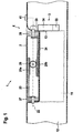
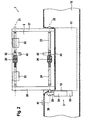
- Fig. 1
- Schematische Darstellung eines Staufachs in einer Mittelkonsole mit geschlossenem Staufachdeckel,
- Fig. 2
- Darstellung des Staufachs mit in einer Richtung geöffnetem Staufachdeckel,
- Fig. 3
- Darstellung des Staufachs mit in Gegen-Richtung geöffnetem Staufachdeckel,
- Fig. 4
- Ein Staufach mit im Staufachdeckel angeordnetem Energiespeicher,
- Fig. 5
- Darstellung des freigeschnittenen Staufachdeckels,
- Fig. 6
- Darstellung einer alternativen Ausführung des Staufachdeckels mit einer Zahnstange.
Claims (15)
- Staufach für ein Fahrzeug, vorzugsweise für Personenkraftwagen,
mit einem Ablagefach (11) und einem schwenkbar gelagerten Staufachdeckel (2) zum Verschließen des Ablagefachs,
wobei der Staufachdeckel an zwei gegenüberliegenden Längskanten je eine Drehachse (21, 22) aufweist und in zwei Richtungen zu öffnen ist und wahlweise um die eine Drehachse oder die andere Drehachse schwenkt, wobei in Schließstellung des Staufachdeckels (2) beide Drehachsen (21, 22) verriegelt sind und eine Antriebsvorrichtung (3) den Staufachdeckel (2) nach Lösen der Verriegelung einer Drehachse (21 bzw. 22) automatisch angetrieben um die andere Drehachse (22 bzw. 21) in Öffnungsrichtung schwenkt,
dadurch gekennzeichnet, dass die Antriebsvorrichtung (3) einen zweigeteilt ausgebildeten Energiespeicher (32, 33) aufweist und jede Drehachse (21, 22) mit einem Energiespeicher (32, 33) verbunden ist und zumindest der Energiespeicher (32) der ersten Drehachse (21) innerhalb des Staufachdeckels (2) angeordnet ist. - Staufach nach Anspruch 1,
dadurch gekennzeichnet, dass der Energiespeicher (32, 33) beim manuellen Schließen des Staufachdeckels (2) geladen wird und sich beim automatisch angetriebenen Öffnen des Staufachdeckels (2) entlädt. - Staufach nach Anspruch 1 oder 2,
dadurch gekennzeichnet, dass der Energiespeicher (32, 33) eine Feder mit Dämpfungseinrichtung aufweist, so dass die Öffnungsbewegung gedämpft erfolgt. - Staufach nach einem der Ansprüche 1 bis 3,
dadurch gekennzeichnet, dass an einer Seitenwand (13) des Ablagefachs (11) eine Haltevorrichtung (4) angeordnet ist, die zum Verriegeln beider Drehachsen (21, 22) ausgebildet ist. - Staufach nach Anspruch 4
dadurch gekennzeichnet, dass im Bereich der Seitenwand (13) des Ablagefachs (11) ein Entriegelungstaster (41) angeordnet ist, der mit der Haltevorrichtung (4) verbunden ist und mit dieser zum Entriegeln einer Drehachse (21, bzw. 22) zusammenwirkt. - Staufach nach Anspruch 4 oder 5,
dadurch gekennzeichnet, dass der Staufachdeckel (2) im Bereich der Drehachsen (21, 22) angeordnete Teilachsen (23, 24) aufweist, die entlang der beiden Drehachsen (21, 22) verlaufen und vorzugsweise vorgesehen ist, dass je eine Teilachse (24) sich an einer Seite des Staufachdeckels (2) über diesen hinaus erstreckt und in die Haltevorrichtung (4) zum Verriegeln und/oder Lagern des Staufachdeckels (2) eingreift. - Staufach nach einem der Ansprüche 1 bis 6,
dadurch gekennzeichnet, dass eine Drehachse (21 bzw. 22) zwei an dem Staufachdeckel (2) entlang der Drehachse (21 bzw. 22) linear verschiebbare Teilachsen (23, 24) aufweist, wobei jede Teilachse (23 bzw. 24) an dem der anderen Teilachse (24 bzw. 23) zugewandten Ende eine Zahnstange (25) aufweist, die über ein Zahnrad (26) mit der Zahnstange (25) der anderen Teilachse (23 bzw. 24) so kämmt, dass sich die Teilachsen (23, 24) gegenläufig bewegen. - Staufach nach einem der Ansprüche 1 bis 7,
dadurch gekennzeichnet, dass eine Drehachse (21, 22) eine Sperrvorrichtung (42) aufweist, die so ausgebildet ist, dass sie eine Entriegelung der Drehachse (21, 22) bei geöffnetem Staufachdeckel (2) sperrt. - Staufach nach einem der Ansprüche 3 bis 8,
dadurch gekennzeichnet, dass der Energiespeicher (32) der ersten Drehachse (21) im Staufachdeckel (2) im Bereich der Drehachse (21) angeordnet ist und der Energiespeicher (33) der zweiten Drehachse (22) im Bereich einer Seitenwand (13) des Ablagefachs (11) angeordnet ist. - Staufach nach einem der Ansprüche 3 bis 9,
dadurch gekennzeichnet, dass die Haltevorrichtung (4) einen beide Drehachsen (21, 22) verbindenden Bügel (28) aufweist, der mit dem Energiespeicher (33) der zweiten Drehachse (22) verbunden ist und den Staufachdeckel (2) nach dem Entriegeln der ersten Drehachse (21) um die zweite Drehachse (22) in Öffnungsrichtung schwenkt. - Staufach nach Anspruch 10,
dadurch gekennzeichnet, dass der Bügel (27, 28) so ausgebildet ist, dass beim Entriegeln der zweiten Drehachse (22) der Bügel (28) ortsfest an der Seitenwand (13) angeordnet ist und das Drehlager der ersten Drehachse (21) bildet und dass beim Entriegeln der ersten Drehachse (21) der Bügel (27, 28) mit dem Staufachdeckel (2) mitschwenkt. - Staufach nach einem der Ansprüche 1 bis 3,
dadurch gekennzeichnet, dass der Energiespeicher (32) der ersten Drehachse (21) und der Energiespeicher (33) der zweiten Drehachse (22) im Staufachdeckel (2) aufgenommen ist und vorzugsweise beide Energiespeicher (32, 33) im Bereich der Drehachsen (21, 22) angeordnet sind. - Staufach nach Anspruch 12,
dadurch gekennzeichnet, dass der Energiespeicher (32) der ersten Drehachse (21) mit dem Energiespeicher (33) der zweiten Drehachse (22) verbunden ist, vorzugsweise mittels einer Zahnstange (35) und/oder einer biegsamen Welle (36), so dass jeweils beide Energiespeicher (32, 33) zum Schwenken des Staufachdeckels (2) um eine Drehachse (21, 22) zusammenwirken. - Staufach nach Anspruch 12 oder 13,
dadurch gekennzeichnet, dass der Energiespeicher (32, 33) zum Speichern der Energie zu gleichen Teilen in dem Energiespeicher (32) der ersten Drehachse (21) und dem Energiespeicher (33) der zweiten Drehachse (22) ausgebildet ist, indem beim Schwenken des Staufachdeckels (2) die Zahnstange und/oder die biegsamen Welle (36) Energie zwischen den Energiespeichern (32, 33) überträgt. - Staufach nach einem der Ansprüche 12 bis 14,
dadurch gekennzeichnet, dass die Teilachsen (24) an ihrem über den Staufachdeckel (2) hinausgreifenden Ende einen vorzugsweise elliptisch oder eckig geformten Nocken (37) aufweisen, der bei verriegelter Haltevorrichtung (4) so in diese eingreift, dass die jeweilige Teilachse (24) drehfest in der Haltevorrichtung (4) gelagert ist.
Applications Claiming Priority (3)
| Application Number | Priority Date | Filing Date | Title |
|---|---|---|---|
| DE10228399 | 2002-06-25 | ||
| DE10228399A DE10228399A1 (de) | 2002-06-25 | 2002-06-25 | Staufach für ein Fahrzeug |
| PCT/EP2003/005305 WO2004000607A1 (de) | 2002-06-25 | 2003-05-21 | Staufach für ein fahrzeug |
Publications (2)
| Publication Number | Publication Date |
|---|---|
| EP1515871A1 EP1515871A1 (de) | 2005-03-23 |
| EP1515871B1 true EP1515871B1 (de) | 2005-11-09 |
Family
ID=29723446
Family Applications (1)
| Application Number | Title | Priority Date | Filing Date |
|---|---|---|---|
| EP03732432A Expired - Lifetime EP1515871B1 (de) | 2002-06-25 | 2003-05-21 | Staufach für ein fahrzeug |
Country Status (6)
| Country | Link |
|---|---|
| US (1) | US7523975B2 (de) |
| EP (1) | EP1515871B1 (de) |
| JP (1) | JP2006507169A (de) |
| DE (2) | DE10228399A1 (de) |
| ES (1) | ES2251689T3 (de) |
| WO (1) | WO2004000607A1 (de) |
Families Citing this family (15)
| Publication number | Priority date | Publication date | Assignee | Title |
|---|---|---|---|---|
| EP1854943A4 (de) * | 2005-01-18 | 2014-08-06 | Kojima Press Kogyo Kk | Öffnungs-/schliess-verriegelungsvorrichtung für handschuhfach |
| DE102005012305B4 (de) * | 2005-03-17 | 2007-01-25 | Daimlerchrysler Ag | Führung |
| JP2007145236A (ja) * | 2005-11-29 | 2007-06-14 | Toyoda Gosei Co Ltd | 収納体 |
| DE102006008663A1 (de) * | 2006-02-24 | 2007-01-25 | Audi Ag | Vorrichtung zum Abdecken eines Ablagefachs |
| DE102006033043B4 (de) * | 2006-07-14 | 2010-03-18 | Johnson Controls Interiors Gmbh & Co. Kg | Ver- und Entriegelungsmechanismus für den Deckel eines Handschuhfachs |
| FR2930582B1 (fr) * | 2008-04-23 | 2010-06-04 | Adler Sas | Dispositif de verrouillage de porte a cremone |
| JP5629131B2 (ja) * | 2010-06-09 | 2014-11-19 | 株式会社ニフコ | ロック装置 |
| DE102011087017B4 (de) | 2011-11-24 | 2022-01-27 | Lisa Dräxlmaier GmbH | Fachdeckel |
| ITMI20130665A1 (it) * | 2013-04-23 | 2014-10-24 | Ferretti Spa | Imbarcazione con portellone poppiero con doppia possibilita' di apertura |
| DE102013014155A1 (de) * | 2013-08-24 | 2014-04-24 | Daimler Ag | Behälter umfassend ein Ablagefach mit einer Wandung und einen Auflagedeckel zum Verschließen des Gehäusefachs |
| US9451716B1 (en) * | 2015-06-27 | 2016-09-20 | Intel Corporation | Serviceable chassis for devices |
| GB2558853B (en) * | 2015-11-20 | 2021-01-13 | Piolax Inc | Lock device |
| DE112018005430T5 (de) * | 2017-11-10 | 2020-07-16 | Tok, Inc. | Scharnierarm-Dämpfungsmechanismus |
| FR3073801B3 (fr) * | 2017-11-20 | 2019-11-29 | Inteva Products, Llc | Actionneur de boite a gants pour verrouillage electrique et deverrouillage electrique |
| CN111852242A (zh) * | 2020-06-18 | 2020-10-30 | 北京汽车股份有限公司 | 传动控制装置及车辆 |
Family Cites Families (28)
| Publication number | Priority date | Publication date | Assignee | Title |
|---|---|---|---|---|
| US3810275A (en) * | 1972-06-26 | 1974-05-14 | Gsw Appliances Ltd | Hinge structure |
| JPS5663648U (de) * | 1979-10-24 | 1981-05-28 | ||
| JP2789223B2 (ja) * | 1989-06-05 | 1998-08-20 | 株式会社ニフコ | 蓋体の開閉装置 |
| US5067755A (en) * | 1989-06-30 | 1991-11-26 | James C Thomas | Locking mechanism for a safe door |
| JP3208453B2 (ja) * | 1990-12-14 | 2001-09-10 | 株式会社パイオラックス | 自動車のコンソールボックス用等の両開き開閉装置 |
| JP3052152B2 (ja) | 1991-01-16 | 2000-06-12 | 株式会社パイオラックス | 自動車のコンソールボックス用等の両開き開閉装置 |
| JP2521395Y2 (ja) | 1991-02-25 | 1996-12-25 | 株式会社パイオラックス | 蓋の開閉装置 |
| DE69312134T2 (de) | 1992-03-25 | 1997-12-11 | Kato Hatsujo Kaisha Ltd | Vorrichtung zum Öffnen und Schliessen eines Deckels |
| US5647652A (en) * | 1995-12-20 | 1997-07-15 | Chrysler Corporation | Dual-hinged center console |
| US6142333A (en) * | 1996-05-31 | 2000-11-07 | Piolax Inc. | Bi-directional lid opening apparatus |
| US5826922A (en) * | 1997-03-13 | 1998-10-27 | Silicon Graphics, Inc. | Rotary latch assembly for a computer housing |
| US6116674A (en) * | 1997-09-05 | 2000-09-12 | Ford Motor Company | Removable console for use with a vehicle |
| US5937583A (en) * | 1997-10-31 | 1999-08-17 | Lamperti; Riccardo | Device for closing road wells in vehicle and pedestrian areas |
| US5951083A (en) * | 1997-11-13 | 1999-09-14 | Chrysler Corporation | Glove box door damper |
| US6244647B1 (en) * | 1999-11-18 | 2001-06-12 | Visteon Corporation | Controlled rate hinge responsive to weight |
| US20020002757A1 (en) * | 2000-05-15 | 2002-01-10 | Hyp Eric D. | Double hinge console latch |
| US20030173369A1 (en) * | 2000-12-07 | 2003-09-18 | Rexam Cosmetic Packaging, Inc. | Container system |
| KR20040094284A (ko) * | 2001-04-30 | 2004-11-09 | 사우스코 인코포레이티드 | 양쪽 개방식 콘솔 리드 |
| US6669243B2 (en) * | 2001-07-03 | 2003-12-30 | Piolax Inc. | Side lock assembly for storage bin |
| US6857538B2 (en) * | 2002-04-25 | 2005-02-22 | Tsong-Yow Lin | Garbage bin with cover |
| DE10231329A1 (de) * | 2002-07-11 | 2004-01-29 | Huf Hülsbeck & Fürst Gmbh & Co. Kg | Verschluss mit zwei Riegelstangen, insbesondere für Fahrzeuge |
| JP2004175151A (ja) * | 2002-11-25 | 2004-06-24 | Nifco Inc | ダンパユニット及びこのダンパユニットを用いたクローブボックス装置 |
| US6788914B1 (en) * | 2003-03-20 | 2004-09-07 | Kabushiki Kaisha Toshiba | Image forming apparatus |
| US7216459B1 (en) * | 2003-07-02 | 2007-05-15 | Neenah Foundry Company | Access hatch cover assembly with lift-assist assembly and method therefor |
| KR100535763B1 (ko) * | 2003-11-19 | 2005-12-12 | 현대모비스 주식회사 | 글로브박스의 로드 작동장치 |
| JP4381831B2 (ja) * | 2004-01-15 | 2009-12-09 | マツダ株式会社 | 扉用ロック機構及び扉用ロックユニット |
| JP2005247232A (ja) * | 2004-03-08 | 2005-09-15 | Nifco Inc | リッド開閉装置及びそれを用いた小物入れ装置 |
| JP4412234B2 (ja) * | 2005-05-24 | 2010-02-10 | 豊田合成株式会社 | グローブボックス |
-
2002
- 2002-06-25 DE DE10228399A patent/DE10228399A1/de not_active Withdrawn
-
2003
- 2003-05-21 EP EP03732432A patent/EP1515871B1/de not_active Expired - Lifetime
- 2003-05-21 ES ES03732432T patent/ES2251689T3/es not_active Expired - Lifetime
- 2003-05-21 US US10/518,747 patent/US7523975B2/en not_active Expired - Fee Related
- 2003-05-21 WO PCT/EP2003/005305 patent/WO2004000607A1/de not_active Ceased
- 2003-05-21 JP JP2004514644A patent/JP2006507169A/ja active Pending
- 2003-05-21 DE DE50301630T patent/DE50301630D1/de not_active Expired - Lifetime
Also Published As
| Publication number | Publication date |
|---|---|
| DE50301630D1 (de) | 2005-12-15 |
| US20060163898A1 (en) | 2006-07-27 |
| WO2004000607A1 (de) | 2003-12-31 |
| EP1515871A1 (de) | 2005-03-23 |
| DE10228399A1 (de) | 2004-01-15 |
| US7523975B2 (en) | 2009-04-28 |
| ES2251689T3 (es) | 2006-05-01 |
| JP2006507169A (ja) | 2006-03-02 |
Similar Documents
| Publication | Publication Date | Title |
|---|---|---|
| EP3221182B1 (de) | Verriegelungsvorrichtung, insbesondere zur verriegelung einer lehne eines fahrzeugsitzes mit einer fahrzeugstruktur | |
| EP1515871A1 (de) | Staufach für ein fahrzeug | |
| DE102008022419A1 (de) | Antriebseinrichtung für Kraftfahrzeugschwenksitz | |
| DE19821583A1 (de) | Kraftfahrzeug-Instrumentenbrett-Baugruppe mit modularem Handschuhfach | |
| DE102015117812B4 (de) | Anordnung eines Freigabemechanismus für ein Heckklappenfach | |
| DE102008018321A1 (de) | Mittelkonsole für ein Kraftfahrzeug | |
| DE102006013735B4 (de) | Heckklappe für Fahrzeuge | |
| DE9310058U1 (de) | Heckklappe für Kraftwagen | |
| DE102009058988A1 (de) | Kraftfahrzeug | |
| DE10107079B4 (de) | Verdeckkastendeckel für ein Cabrio | |
| DE102005055138B4 (de) | Zweiseitig zu öffnender Behälter | |
| DE102023100355A1 (de) | Angetriebenes federsystem für eine haube | |
| DE10039305B4 (de) | Führungsmechanismus für eine Abdeckplatte eines Ablagefachs in einem Fahrzeug | |
| EP1112882A2 (de) | Cabriolet-Fahrzeug | |
| DE102005049999A1 (de) | Abdeckvorrichtung für einen Laderaum eines Kraftfahrzeugs | |
| DE19962069A1 (de) | Verschlußvorrichtung für Fahrzeugverdecke | |
| DE102017100935A1 (de) | Verriegelungsmechanismus für einen Deckel eines Ablagefachs eines Kraftfahrzeugs | |
| DE102009001178B4 (de) | Staufach | |
| DE4229695A1 (de) | Kraftwagensitz mit einer Aufnahmeeinrichtung für Ausrüstungsgegenstände | |
| DE102005031722B4 (de) | Abdeckvorrichtung für einen Laderaum eines Fahrzeugs | |
| DE19549463A1 (de) | Längsverstellmechanismus eines Fahrzeugsitzes mit/ohne Memory | |
| DE202005021095U1 (de) | Klappbare Armauflage mit Dämpfung | |
| DE102024000846B3 (de) | Ablagefachanordnung für ein Fahrzeug und Fahrzeug | |
| DE102004059027A1 (de) | Fahrzeugsitz | |
| DE102004005265B4 (de) | Gehäuse mit Deckel und Kinematikrahmen |
Legal Events
| Date | Code | Title | Description |
|---|---|---|---|
| PUAI | Public reference made under article 153(3) epc to a published international application that has entered the european phase |
Free format text: ORIGINAL CODE: 0009012 |
|
| 17P | Request for examination filed |
Effective date: 20041210 |
|
| AK | Designated contracting states |
Kind code of ref document: A1 Designated state(s): AT BE BG CH CY CZ DE DK EE ES FI FR GB GR HU IE IT LI LU MC NL PT RO SE SI SK TR |
|
| GRAP | Despatch of communication of intention to grant a patent |
Free format text: ORIGINAL CODE: EPIDOSNIGR1 |
|
| RBV | Designated contracting states (corrected) |
Designated state(s): DE ES FR GB IT |
|
| GRAS | Grant fee paid |
Free format text: ORIGINAL CODE: EPIDOSNIGR3 |
|
| GRAA | (expected) grant |
Free format text: ORIGINAL CODE: 0009210 |
|
| AK | Designated contracting states |
Kind code of ref document: B1 Designated state(s): DE ES FR GB IT |
|
| REG | Reference to a national code |
Ref country code: GB Ref legal event code: FG4D Free format text: NOT ENGLISH |
|
| REF | Corresponds to: |
Ref document number: 50301630 Country of ref document: DE Date of ref document: 20051215 Kind code of ref document: P |
|
| GBT | Gb: translation of ep patent filed (gb section 77(6)(a)/1977) |
Effective date: 20060116 |
|
| REG | Reference to a national code |
Ref country code: ES Ref legal event code: FG2A Ref document number: 2251689 Country of ref document: ES Kind code of ref document: T3 |
|
| PGFP | Annual fee paid to national office [announced via postgrant information from national office to epo] |
Ref country code: FR Payment date: 20060519 Year of fee payment: 4 |
|
| PGFP | Annual fee paid to national office [announced via postgrant information from national office to epo] |
Ref country code: ES Payment date: 20060530 Year of fee payment: 4 |
|
| PGFP | Annual fee paid to national office [announced via postgrant information from national office to epo] |
Ref country code: IT Payment date: 20060531 Year of fee payment: 4 |
|
| ET | Fr: translation filed | ||
| PLBE | No opposition filed within time limit |
Free format text: ORIGINAL CODE: 0009261 |
|
| STAA | Information on the status of an ep patent application or granted ep patent |
Free format text: STATUS: NO OPPOSITION FILED WITHIN TIME LIMIT |
|
| 26N | No opposition filed |
Effective date: 20060810 |
|
| GBPC | Gb: european patent ceased through non-payment of renewal fee |
Effective date: 20070521 |
|
| REG | Reference to a national code |
Ref country code: FR Ref legal event code: ST Effective date: 20080131 |
|
| PG25 | Lapsed in a contracting state [announced via postgrant information from national office to epo] |
Ref country code: GB Free format text: LAPSE BECAUSE OF NON-PAYMENT OF DUE FEES Effective date: 20070521 |
|
| PG25 | Lapsed in a contracting state [announced via postgrant information from national office to epo] |
Ref country code: FR Free format text: LAPSE BECAUSE OF NON-PAYMENT OF DUE FEES Effective date: 20070531 |
|
| REG | Reference to a national code |
Ref country code: ES Ref legal event code: FD2A Effective date: 20070522 |
|
| PG25 | Lapsed in a contracting state [announced via postgrant information from national office to epo] |
Ref country code: ES Free format text: LAPSE BECAUSE OF NON-PAYMENT OF DUE FEES Effective date: 20070522 |
|
| PG25 | Lapsed in a contracting state [announced via postgrant information from national office to epo] |
Ref country code: IT Free format text: LAPSE BECAUSE OF NON-PAYMENT OF DUE FEES Effective date: 20070521 |
|
| PGFP | Annual fee paid to national office [announced via postgrant information from national office to epo] |
Ref country code: DE Payment date: 20180731 Year of fee payment: 16 |
|
| REG | Reference to a national code |
Ref country code: DE Ref legal event code: R081 Ref document number: 50301630 Country of ref document: DE Owner name: ZIPPERLE, RALF, DE Free format text: FORMER OWNER: DAIMLER AG, 70327 STUTTGART, DE |
|
| REG | Reference to a national code |
Ref country code: DE Ref legal event code: R119 Ref document number: 50301630 Country of ref document: DE |
|
| PG25 | Lapsed in a contracting state [announced via postgrant information from national office to epo] |
Ref country code: DE Free format text: LAPSE BECAUSE OF NON-PAYMENT OF DUE FEES Effective date: 20191203 |