EP1515097A1 - Luftreiniger und Steuerungsverfahren dafür - Google Patents
Luftreiniger und Steuerungsverfahren dafür Download PDFInfo
- Publication number
- EP1515097A1 EP1515097A1 EP04075102A EP04075102A EP1515097A1 EP 1515097 A1 EP1515097 A1 EP 1515097A1 EP 04075102 A EP04075102 A EP 04075102A EP 04075102 A EP04075102 A EP 04075102A EP 1515097 A1 EP1515097 A1 EP 1515097A1
- Authority
- EP
- European Patent Office
- Prior art keywords
- air
- room
- cleaned
- room air
- fan
- Prior art date
- Legal status (The legal status is an assumption and is not a legal conclusion. Google has not performed a legal analysis and makes no representation as to the accuracy of the status listed.)
- Withdrawn
Links
- 238000000034 method Methods 0.000 title claims abstract description 35
- 239000000428 dust Substances 0.000 claims abstract description 46
- 239000000203 mixture Substances 0.000 claims abstract description 13
- 239000002245 particle Substances 0.000 claims abstract description 13
- 239000007789 gas Substances 0.000 claims description 35
- 150000001450 anions Chemical class 0.000 claims description 22
- 238000001816 cooling Methods 0.000 claims description 22
- 238000010438 heat treatment Methods 0.000 claims description 22
- QVGXLLKOCUKJST-UHFFFAOYSA-N atomic oxygen Chemical compound [O] QVGXLLKOCUKJST-UHFFFAOYSA-N 0.000 claims description 20
- 229910052760 oxygen Inorganic materials 0.000 claims description 20
- 239000001301 oxygen Substances 0.000 claims description 20
- 150000003505 terpenes Chemical class 0.000 claims description 13
- 235000007586 terpenes Nutrition 0.000 claims description 13
- UGFAIRIUMAVXCW-UHFFFAOYSA-N Carbon monoxide Chemical compound [O+]#[C-] UGFAIRIUMAVXCW-UHFFFAOYSA-N 0.000 claims description 4
- 229910002091 carbon monoxide Inorganic materials 0.000 claims description 4
- 150000004767 nitrides Chemical class 0.000 claims description 4
- 238000007599 discharging Methods 0.000 claims description 2
- 230000035943 smell Effects 0.000 description 10
- 238000004140 cleaning Methods 0.000 description 6
- 230000000694 effects Effects 0.000 description 3
- RAHZWNYVWXNFOC-UHFFFAOYSA-N Sulphur dioxide Chemical compound O=S=O RAHZWNYVWXNFOC-UHFFFAOYSA-N 0.000 description 2
- 125000003118 aryl group Chemical group 0.000 description 2
- 150000001768 cations Chemical class 0.000 description 2
- 230000006870 function Effects 0.000 description 2
- 230000004048 modification Effects 0.000 description 2
- 238000012986 modification Methods 0.000 description 2
- 230000001954 sterilising effect Effects 0.000 description 2
- 238000004659 sterilization and disinfection Methods 0.000 description 2
- 239000000126 substance Substances 0.000 description 2
- 241000894006 Bacteria Species 0.000 description 1
- 241000238631 Hexapoda Species 0.000 description 1
- 230000005679 Peltier effect Effects 0.000 description 1
- 210000000467 autonomic pathway Anatomy 0.000 description 1
- 239000008280 blood Substances 0.000 description 1
- 210000004369 blood Anatomy 0.000 description 1
- 230000008859 change Effects 0.000 description 1
- 230000003247 decreasing effect Effects 0.000 description 1
- 238000004332 deodorization Methods 0.000 description 1
- 230000004217 heart function Effects 0.000 description 1
- 230000000749 insecticidal effect Effects 0.000 description 1
- 230000004199 lung function Effects 0.000 description 1
- 238000004519 manufacturing process Methods 0.000 description 1
- 239000000463 material Substances 0.000 description 1
- 239000002244 precipitate Substances 0.000 description 1
- 230000004936 stimulating effect Effects 0.000 description 1
- 238000005728 strengthening Methods 0.000 description 1
- 239000002699 waste material Substances 0.000 description 1
Images


Classifications
-
- F—MECHANICAL ENGINEERING; LIGHTING; HEATING; WEAPONS; BLASTING
- F24—HEATING; RANGES; VENTILATING
- F24F—AIR-CONDITIONING; AIR-HUMIDIFICATION; VENTILATION; USE OF AIR CURRENTS FOR SCREENING
- F24F5/00—Air-conditioning systems or apparatus not covered by F24F1/00 or F24F3/00, e.g. using solar heat or combined with household units such as an oven or water heater
- F24F5/0042—Air-conditioning systems or apparatus not covered by F24F1/00 or F24F3/00, e.g. using solar heat or combined with household units such as an oven or water heater characterised by the application of thermo-electric units or the Peltier effect
-
- B—PERFORMING OPERATIONS; TRANSPORTING
- B01—PHYSICAL OR CHEMICAL PROCESSES OR APPARATUS IN GENERAL
- B01D—SEPARATION
- B01D46/00—Filters or filtering processes specially modified for separating dispersed particles from gases or vapours
- B01D46/42—Auxiliary equipment or operation thereof
-
- F—MECHANICAL ENGINEERING; LIGHTING; HEATING; WEAPONS; BLASTING
- F24—HEATING; RANGES; VENTILATING
- F24F—AIR-CONDITIONING; AIR-HUMIDIFICATION; VENTILATION; USE OF AIR CURRENTS FOR SCREENING
- F24F11/00—Control or safety arrangements
- F24F11/70—Control systems characterised by their outputs; Constructional details thereof
- F24F11/72—Control systems characterised by their outputs; Constructional details thereof for controlling the supply of treated air, e.g. its pressure
- F24F11/74—Control systems characterised by their outputs; Constructional details thereof for controlling the supply of treated air, e.g. its pressure for controlling air flow rate or air velocity
- F24F11/77—Control systems characterised by their outputs; Constructional details thereof for controlling the supply of treated air, e.g. its pressure for controlling air flow rate or air velocity by controlling the speed of ventilators
-
- F—MECHANICAL ENGINEERING; LIGHTING; HEATING; WEAPONS; BLASTING
- F24—HEATING; RANGES; VENTILATING
- F24F—AIR-CONDITIONING; AIR-HUMIDIFICATION; VENTILATION; USE OF AIR CURRENTS FOR SCREENING
- F24F8/00—Treatment, e.g. purification, of air supplied to human living or working spaces otherwise than by heating, cooling, humidifying or drying
- F24F8/30—Treatment, e.g. purification, of air supplied to human living or working spaces otherwise than by heating, cooling, humidifying or drying by ionisation
-
- F—MECHANICAL ENGINEERING; LIGHTING; HEATING; WEAPONS; BLASTING
- F24—HEATING; RANGES; VENTILATING
- F24F—AIR-CONDITIONING; AIR-HUMIDIFICATION; VENTILATION; USE OF AIR CURRENTS FOR SCREENING
- F24F8/00—Treatment, e.g. purification, of air supplied to human living or working spaces otherwise than by heating, cooling, humidifying or drying
- F24F8/60—Treatment, e.g. purification, of air supplied to human living or working spaces otherwise than by heating, cooling, humidifying or drying by adding oxygen
-
- F—MECHANICAL ENGINEERING; LIGHTING; HEATING; WEAPONS; BLASTING
- F24—HEATING; RANGES; VENTILATING
- F24F—AIR-CONDITIONING; AIR-HUMIDIFICATION; VENTILATION; USE OF AIR CURRENTS FOR SCREENING
- F24F8/00—Treatment, e.g. purification, of air supplied to human living or working spaces otherwise than by heating, cooling, humidifying or drying
- F24F8/80—Self-contained air purifiers
-
- F—MECHANICAL ENGINEERING; LIGHTING; HEATING; WEAPONS; BLASTING
- F24—HEATING; RANGES; VENTILATING
- F24F—AIR-CONDITIONING; AIR-HUMIDIFICATION; VENTILATION; USE OF AIR CURRENTS FOR SCREENING
- F24F11/00—Control or safety arrangements
- F24F11/30—Control or safety arrangements for purposes related to the operation of the system, e.g. for safety or monitoring
-
- F—MECHANICAL ENGINEERING; LIGHTING; HEATING; WEAPONS; BLASTING
- F24—HEATING; RANGES; VENTILATING
- F24F—AIR-CONDITIONING; AIR-HUMIDIFICATION; VENTILATION; USE OF AIR CURRENTS FOR SCREENING
- F24F2110/00—Control inputs relating to air properties
- F24F2110/10—Temperature
-
- F—MECHANICAL ENGINEERING; LIGHTING; HEATING; WEAPONS; BLASTING
- F24—HEATING; RANGES; VENTILATING
- F24F—AIR-CONDITIONING; AIR-HUMIDIFICATION; VENTILATION; USE OF AIR CURRENTS FOR SCREENING
- F24F2110/00—Control inputs relating to air properties
- F24F2110/20—Humidity
-
- F—MECHANICAL ENGINEERING; LIGHTING; HEATING; WEAPONS; BLASTING
- F24—HEATING; RANGES; VENTILATING
- F24F—AIR-CONDITIONING; AIR-HUMIDIFICATION; VENTILATION; USE OF AIR CURRENTS FOR SCREENING
- F24F2110/00—Control inputs relating to air properties
- F24F2110/50—Air quality properties
-
- F—MECHANICAL ENGINEERING; LIGHTING; HEATING; WEAPONS; BLASTING
- F24—HEATING; RANGES; VENTILATING
- F24F—AIR-CONDITIONING; AIR-HUMIDIFICATION; VENTILATION; USE OF AIR CURRENTS FOR SCREENING
- F24F2110/00—Control inputs relating to air properties
- F24F2110/50—Air quality properties
- F24F2110/64—Airborne particle content
-
- F—MECHANICAL ENGINEERING; LIGHTING; HEATING; WEAPONS; BLASTING
- F24—HEATING; RANGES; VENTILATING
- F24F—AIR-CONDITIONING; AIR-HUMIDIFICATION; VENTILATION; USE OF AIR CURRENTS FOR SCREENING
- F24F2110/00—Control inputs relating to air properties
- F24F2110/50—Air quality properties
- F24F2110/65—Concentration of specific substances or contaminants
- F24F2110/70—Carbon dioxide
-
- F—MECHANICAL ENGINEERING; LIGHTING; HEATING; WEAPONS; BLASTING
- F24—HEATING; RANGES; VENTILATING
- F24F—AIR-CONDITIONING; AIR-HUMIDIFICATION; VENTILATION; USE OF AIR CURRENTS FOR SCREENING
- F24F2110/00—Control inputs relating to air properties
- F24F2110/50—Air quality properties
- F24F2110/65—Concentration of specific substances or contaminants
- F24F2110/76—Oxygen
-
- F—MECHANICAL ENGINEERING; LIGHTING; HEATING; WEAPONS; BLASTING
- F24—HEATING; RANGES; VENTILATING
- F24F—AIR-CONDITIONING; AIR-HUMIDIFICATION; VENTILATION; USE OF AIR CURRENTS FOR SCREENING
- F24F8/00—Treatment, e.g. purification, of air supplied to human living or working spaces otherwise than by heating, cooling, humidifying or drying
- F24F8/10—Treatment, e.g. purification, of air supplied to human living or working spaces otherwise than by heating, cooling, humidifying or drying by separation, e.g. by filtering
- F24F8/108—Treatment, e.g. purification, of air supplied to human living or working spaces otherwise than by heating, cooling, humidifying or drying by separation, e.g. by filtering using dry filter elements
-
- F—MECHANICAL ENGINEERING; LIGHTING; HEATING; WEAPONS; BLASTING
- F24—HEATING; RANGES; VENTILATING
- F24F—AIR-CONDITIONING; AIR-HUMIDIFICATION; VENTILATION; USE OF AIR CURRENTS FOR SCREENING
- F24F8/00—Treatment, e.g. purification, of air supplied to human living or working spaces otherwise than by heating, cooling, humidifying or drying
- F24F8/20—Treatment, e.g. purification, of air supplied to human living or working spaces otherwise than by heating, cooling, humidifying or drying by sterilisation
- F24F8/24—Treatment, e.g. purification, of air supplied to human living or working spaces otherwise than by heating, cooling, humidifying or drying by sterilisation using sterilising media
-
- F—MECHANICAL ENGINEERING; LIGHTING; HEATING; WEAPONS; BLASTING
- F25—REFRIGERATION OR COOLING; COMBINED HEATING AND REFRIGERATION SYSTEMS; HEAT PUMP SYSTEMS; MANUFACTURE OR STORAGE OF ICE; LIQUEFACTION SOLIDIFICATION OF GASES
- F25B—REFRIGERATION MACHINES, PLANTS OR SYSTEMS; COMBINED HEATING AND REFRIGERATION SYSTEMS; HEAT PUMP SYSTEMS
- F25B21/00—Machines, plants or systems, using electric or magnetic effects
- F25B21/02—Machines, plants or systems, using electric or magnetic effects using Peltier effect; using Nernst-Ettinghausen effect
- F25B21/04—Machines, plants or systems, using electric or magnetic effects using Peltier effect; using Nernst-Ettinghausen effect reversible
-
- Y—GENERAL TAGGING OF NEW TECHNOLOGICAL DEVELOPMENTS; GENERAL TAGGING OF CROSS-SECTIONAL TECHNOLOGIES SPANNING OVER SEVERAL SECTIONS OF THE IPC; TECHNICAL SUBJECTS COVERED BY FORMER USPC CROSS-REFERENCE ART COLLECTIONS [XRACs] AND DIGESTS
- Y02—TECHNOLOGIES OR APPLICATIONS FOR MITIGATION OR ADAPTATION AGAINST CLIMATE CHANGE
- Y02A—TECHNOLOGIES FOR ADAPTATION TO CLIMATE CHANGE
- Y02A50/00—TECHNOLOGIES FOR ADAPTATION TO CLIMATE CHANGE in human health protection, e.g. against extreme weather
- Y02A50/20—Air quality improvement or preservation, e.g. vehicle emission control or emission reduction by using catalytic converters
-
- Y—GENERAL TAGGING OF NEW TECHNOLOGICAL DEVELOPMENTS; GENERAL TAGGING OF CROSS-SECTIONAL TECHNOLOGIES SPANNING OVER SEVERAL SECTIONS OF THE IPC; TECHNICAL SUBJECTS COVERED BY FORMER USPC CROSS-REFERENCE ART COLLECTIONS [XRACs] AND DIGESTS
- Y02—TECHNOLOGIES OR APPLICATIONS FOR MITIGATION OR ADAPTATION AGAINST CLIMATE CHANGE
- Y02B—CLIMATE CHANGE MITIGATION TECHNOLOGIES RELATED TO BUILDINGS, e.g. HOUSING, HOUSE APPLIANCES OR RELATED END-USER APPLICATIONS
- Y02B30/00—Energy efficient heating, ventilation or air conditioning [HVAC]
- Y02B30/70—Efficient control or regulation technologies, e.g. for control of refrigerant flow, motor or heating
Definitions
- the present invention relates to an air cleaner, and more particularly, to an air cleaner and a method of controlling an operation of the same, so as to remove foreign particles from an indoor air, and provide insufficient components of the indoor air, thereby obtaining a comfortable indoor environment with an optimum air state.
- an air cleaner provides a comfortable room environment by carrying out a deodorization function for removing various smells in a room air, and a dust collecting function for removing dust from the room air.
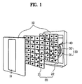
- FIG. 1 and FIG. 2 illustrate a general air cleaner.
- the general air cleaner will be described with reference to the accompanying drawings.
- the general air cleaner is provided with a cabinet 10, a filter assembly 20, a fan assembly 30, and a guide 40.
- the cabinet 10 is provided with an inlet 11 and an outlet 12.
- the room air is drawn into the inside of the cabinet 10 through the inlet 11.
- the inlet 10 is provided in a lower front part of the cabinet 10.
- the air cleaned inside the cabinet 10 is discharged to the room through the outlet 12.
- the outlet 12 is provided in an upper rear part of the cabinet 10.
- the filter assembly 20 is provided with a first filter 21 and a second filter 22.
- the first filter 21 removes the dust from the room air, drawn into the inside of the cabinet 10 through the inlet 11, and the second filter 22 removes smell particles therefrom.
- the first filter 21 is provided inside the cabinet 10 near to the inlet 11, and the second filter 22 is provided in the rear of the first filter 21 so as to remove the fine dust or smell particles unfiltered in the first filter 21.
- the fan assembly 30 is provided with a fan 31 and a fan housing 32.
- the fan 31 is provided inside the cabinet 10 between the filter assembly 20 and the outlet 12, and the fan housing 32 is provided to surround the fan 31.
- the guide 40 is provided inside the cabinet 10 so as to guide the air passing through the fan 31 to the outlet 12.
- the general air cleaner On operation of the general air cleaner, when the fan 31 is rotated, the room air is drawn into the inside of the cabinet 10 through the inlet 11, and the air passes through the filter assembly 20. At this time, the first filter 21 removes the dust from the air, and the second filter 22 removes the smell particles from the air. After that, the filtered air flows into the fan 31, and is guided to the outlet 12 by the guide 40. Then, the air is discharged to the room.
- the general air cleaner has the following disadvantages.
- the general air cleaner simply removes the dust and the smell particles from the room air. Accordingly, even though the air filtered and cleaned by the air cleaner is provided to the room, a user may not feel that the room air is cleaned, whereby it is hard to obtain a user' s reliability.
- the general air cleaner provides the cleaned air having a temperature corresponding to the indoor temperature. Accordingly, in case of that the air discharged from the air cleaner is direct contact with the skin of the user in the winter or summer, the user may feel unpleasant. Thus, in addition to the air cleaner, the user requires an additional air conditioner for cooling or heating the room air.
- the present invention is directed to an air cleaner and a method of controlling an operation of the same using the same that substantially obviates one or more problems due to limitations and disadvantages of the related art.
- An object of the present invention is to provide an air cleaner and a method of operating the same, so as to remove foreign particles from an indoor air, and provide insufficient components of the indoor air, thereby obtaining a comfortable indoor environment with an optimum air state.
- an air cleaner includes a cabinet including an inlet drawing a room air, and an outlet discharging a cleaned air to a room; a filter assembly provided inside the cabinet so as to remove dust and smell particles from the room air drawn through the inlet; a fan provided inside the cabinet so as to discharge the cleaned air to the outlet after drawing the room air; a sensor assembly provided inside the cabinet so as to sense composition of the room air drawn through the inlet; a supplier assembly provided inside the cabinet so as to provide at least one of insufficient components of the room air to the air cleaned by the filter assembly; and a controller controlling the supplier assembly on the basis of data regarding the composition of the room air from the sensor assembly.
- the sensor assembly senses the composition of the room air before the air passes through the filter assembly.
- the sensor assembly includes at least one of a first sensor measuring an oxygen content of the room air; a second sensor measuring a temperature inside the room; a third sensor measuring a dust content of the room air; and a fourth sensor measuring a gas content of the room air.
- the fourth sensor is provided to measure at least one of carbon monoxide CO 2 and nitride oxide NO x .
- the sensor assembly includes a fifth sensor measuring the humidity inside the room.
- the supplier assembly includes a first supplier providing oxygen to the cleaned air.
- the supplier assembly includes a second supplier providing anion to the cleaned air.
- the supplier assembly includes a third supplier providing terpene to the cleaned air.
- thermoelectric module includes a first side having an exothermic or endothermic reaction, and being in contact with the cleaned air; and a second side having an opposite reaction to that of the first side, and not being in contact with the cleaned air.
- the fan has a variable rotation speed.
- the method of controlling the operation of the air cleaner includes the steps of calculating at least one of a dust content and a gas content of the room air on the basis of the sensed data; and controlling a rotation speed of the fan on the basis of at least one of the dust content and the gas content.
- the fan has a variable rotation speed including a high speed when the dust or gas content of the room air is above the previously inputted range; a normal speed when the dust or gas content of the room air is within the previously inputted range; and a low speed when the dust or gas content of the room air is below the previously inputted range.
- the method of controlling the operation of the air cleaner includes the steps detecting that a temperature of the room air is within a summer season temperature range or a winter season temperature range on the basis of the previously inputted data; and cooling or heating the air cleaned and guided to the outlet on the basis of the detected season.
- the cleaned air having a temperature lower than the temperature of the room air at a range between 1°C and 3°C, is provided to an indoor room.
- the cleaned air having a temperature higher than the temperature of the room air at a range between 1°C and 3°C, is provided to an indoor room.
- FIG. 1 is an exploded perspective view illustrating a general air cleaner
- FIG. 2 is a cross-sectional view illustrating a general air cleaner of FIG. 1;
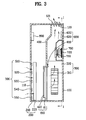
- FIG. 3 is a cross-sectional view illustrating an air cleaner according to the present invention.
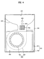
- FIG. 4 is a cross-sectional view taken along line I-I' of FIG. 3;
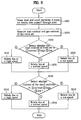
- FIG. 5 is a flow chart illustrating a method of controlling an operation of an air cleaner considering insufficient components of a room air
- FIG. 6 is a flow chart illustrating a method of controlling an operation of an air cleaner considering a gas content and a dust content in a room air;
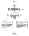
- FIG. 7 is a flow chart illustrating a method of controlling an operation of an air cleaner considering a temperature inside a room.
- the air cleaner according to the present invention is provided with a cabinet 100, a filter assembly 200, a fan 310, a sensor assembly 500, a supplier assembly 600, and a controller 800.
- the cabinet 100 forms the exterior of the air cleaner.
- the cabinet 100 is provided with an inlet 110 and an outlet 120. At this time, a room air is drawn into the inside of the cabinet 100 through the inlet 110, and a cleaned air is discharged to a room through the outlet 120.
- the inlet 110 is provided in a lower front part of the cabinet 100
- the outlet 120 is provided in an upper rear part of the cabinet 100.
- the inlet 110 and the outlet 120 may be provided in other places.
- the inlet 110 may be provided in a central front part or an upper part of the cabinet 100, and may be provided in both sides of the cabinet 100.
- the outlet 120 may be provided in a central upper part or a front part of the cabinet 100, and may be provided in both sides of the cabinet 100.
- the outlet 120 is provided with a plurality of louvers 121.
- the louvers 121 are provided in the outlet 120, a user can easily change a discharge direction of the cleaned air.
- the sensor assembly 500 is provided inside the cabinet 100 in order to sense the composition of the air drawn into the inside of the cabinet 100 through the inlet 110.
- the sensor assembly 500 is formed of at least one of a first sensor 510, a second sensor 520, a third sensor 530 and a fourth sensor 540.
- the first sensor 510 serves as a sensor for measuring the oxygen content
- the second sensor 520 serves as a sensor for measuring a temperature of the room air.
- the third sensor 530 measures the dust content of the room air
- the fourth sensor 540 measures the gas content of the room air.
- the fourth sensor 540 measures the content of at least one of carbon monoxide CO 2 and nitride oxide NO x .
- the fourth sensor 540 may be provided to measure the content of harmful gases or anion.
- the sensor assembly 500 may comprise a fifth sensor 550 additionally.
- the fifth sensor 550 is a sensor for measuring the humidity of the room air.
- the sensor assembly 500 is provided on a passage of the air flowing within the cabinet 100.
- the passage of the air means all spaces through which the air passes from the inlet 110 to the outlet 120.
- the sensor assembly 500 between the inlet 110 and the filter assembly 200.
- the sensor assembly 500 senses the composition of the air before cleaning the air by the filter assembly 200, so that it is possible to obtain correct data regarding the component of the air necessary for the room air.
- the supplier assembly 600 is provided on a passage of the air flowing within the cabinet 100.
- the supplier assembly 600 provides at least one insufficient component of the room air, such as the oxygen, to the air cleaned by the filter assembly 200.
- the supplier assembly 600 is provided with a first supplier 610 providing the oxygen to the cleaned air. Then, the first supplier 610 is provided with a container 611 storing the oxygen, and a tube 612 connected with the container 611. At this time, the container 611 may be provided for charging the oxygen therein, and may be provided for being fixed to the cabinet 100 or separated therefrom. That is, when the user consumes the oxygen, the user exchanges the container 611 with new one, thereby obtaining user's convenience. Meanwhile, as shown in FIG. 3, one end of the tube 612 is provided on a passage of the flowing air, whereby the oxygen stored in the container 611 is provided to the cleaned air.
- the supplier assembly 600 may have a second supplier 620 for providing the anion to the cleaned air.
- the anion neutralizes the harmful cation contained in the air, and the anion has helpful effect on a human body.
- the anion neutralizes and precipitates substances forming the cation such as sulfur dioxide, nitride oxide or carbon monoxide contained in the air, whereby the air is cleaned.
- the anion relaxes the body, purifies the blood of the human body, and activates cells of the body.
- the supplier assembly 600 may have a third supplier 630 for providing terpene to the cleaned air, in which the terpene is the main component of phytoncide.
- the terpene is the main component of phytoncide.
- trees generate the phytoncide that is aromatic chemical material having sterilization and insecticidal characteristics so as to protect themselves from microbe such as bacteria and insects.
- the phytoncide has the following advantageous characteristics: sterilization, secernent of skin waste material, strengthening of the heart and lung functions, and relaxation of mind and body by stimulating autonomic nerve. Accordingly, if the people breathe in the air containing the terpene, it has helpful effects according to an aromatic forest-bath.
- the supplier assembly 600 may be provided inside the cabinet 100 on the passage of the flowing air. However, as shown in FIG. 3, it is preferable to provide the supplier assembly 600 between the fan 310 and the outlet 120.
- the controller 800 controls the supplier assembly 600 on the basis of data analyzing the composition of the air sensed in the sensor assembly 500. For example, in case the room air drawn into the inside of the cabinet 100 has insufficient oxygen, the controller 800 operates the first supplier 610 so as to provide the oxygen to the cleaned air discharged through the outlet 120. Also, if the room air drawn into the inside of the cabinet 100 has insufficient anion, the controller 80 operates the second supplier 620 so as to provide the anion to the air. Also, the controller 800 may provide the terpene to the cleaned air by controlling the third supplier 630.
- the air cleaner according to the present invention may have a cooling/heating device 700 additionally.
- the cooling/heating device 700 is operated to cool or heat the air cleaned inside the cabinet 100, whereby the cleaned air is maintained and provided at an optimum temperature.
- the cooling/heating device 70 is formed of a thermoelectric module.
- the thermoelectric module will be described in brief.
- the thermoelectric module When a current is applied to the thermoelectric module, the thermoelectric module has a low temperature part absorbing an ambient heat, and a high temperature part emitting a heat to the circumference according to a peltier effect. As the amount of the current applied to the thermoelectric module is varied, the amount of heat-exchange is varied between the low temperature part and the high temperature part. Also, when the direction of the current applied to the thermoelectric module is changed, the low temperature part turns to the high temperature part, and the high temperature part turns to the low temperature part.
- thermoelectric module has no mechanical operation parts, noise and vibration. Furthermore, it is possible for the thermoelectric module to perform the cooling and heating processes at a high speed, and to control a temperature therein. In addition, the thermoelectric module has miniaturization and lightness in weight. In this respect, the air cleaner according to the present invention adopts the thermoelectric module as the cooling/heating device 700.
- the cooling/heating device 700 is provided inside the cabinet 100. At this time, in case of that a first side 710 of the thermoelectric module for absorbing the heat is provided for being in contact with the cleaned air, a second side 720 of the thermoelectric module for emitting the heat is provided not to be in contact with the cleaner air. Meanwhile, in case of that the first side 710 of the thermoelectric module for emitting the heat is provided for being in contact with the cleaned air, the second side 720 of the thermoelectric module for absorbing the heat is provided not to be in contact with the cleaned air.
- the cooling/heating device 700 is controlled by the controller 800.
- FIG. 5 is a flow chart illustrating a method of controlling an operation of the air cleaner considering insufficient components of a room air.
- the fan 310 On operating the air cleaner, the fan 310 is rotated, whereby the fan 310 draws the room air into the inside of the cabinet 100 through the inlet 110. Then, the sensor assembly 500 senses the room air (S110), and transmits the data to the controller 800.
- the data transmitted to the controller 800 includes at least one of the oxygen content and the anion content in the room air.
- the data may include information regarding the dust content, the gas content, and the temperature and the humidity of the room air.
- the air After the air passes through the sensor assembly 500, the air flows into the filter assembly 200. At this time, the first filter 210 removes the dust from the flowing air, and the second filter 220 removes the fine dust and the gas such as the smell particles from the air passing through the first filter 210. Subsequently, the air cleaned by the filter assembly 200 is guided to the outlet 120 through the fan 310.
- the controller 80 receives the data having the information regarding to the composition of the room air from the sensor assembly 500, and compares the received data with previously inputted data, thereby calculating the insufficient component of the room air and the content thereof (S120).
- the previously inputted data is set within a range of the content helpful to the human body.
- the user may input the data previously and optionally through a controller panel (not shown).
- the controller 800 analyzes the composition of the room air
- the controller 80 detects the insufficient components of the room air (S130, S150). Then, the controller 800 controls the supplier assembly 600 so as to provide at least one of the insufficient components of the room air to the air flowing to the outlet 120 (S140, S160).
- this process step will be described in more detail.
- the sensor assembly 500 may include a sensor for sensing the anion content of the room air so as to control the second supplier 620 on the basis of the insufficient amount of the anion.
- the fourth sensor 540 of measuring the gas content may serve as the sensor for sensing the anion content, or an additional sensor may be provided so as to sense the anion content. If there is no sensor for sensing the anion content of the room air, the controller 800 periodically operates the second supplier 620.
- the controller 800 controls the third supplier 630 so as to provide the terpene to the cleaned air flowing to the outlet 120 (S170). At this time, it is possible to provide the terpene to the cleaned air periodically during operating the air cleaner. Or, the third supplier 640 may provide the terpene to the cleaned air in case it is detected that the terpene is insufficient for the room air.
- the cleaned air it is possible to provide at least one of the insufficient components of the room air to the cleaned air by the supplier assembly 600. Then, the cleaned air, to which at least one of the insufficient components of the room air is provided, is discharged to the room through the outlet 120. Accordingly, the cleaned air provides the oxygen, the anion or the terpene in a sufficient amount, thereby obtaining the optimum and comfortable room environment.
- the controller 800 controls the rotation speed of the fan 310 considering of the gas content, the dust and the smell particles. Accordingly, the method described in FIG. 6 may be performed with the method described in FIG. 5 simultaneously. Hereinafter, this method will be described in detail.
- the sensor assembly 500 After the sensor assembly 500 senses the dust content and the gas content of the room air (S210), the sensor assembly 500 transmits the information regarding the dust content and the gas content to the controller 800. Then, the controller 80 calculates at least one of the dust content and the gas content contained in the room air on the basis of the data sensed by the sensor assembly 500 (S220).
- the controller 800 compares the result with the previously inputted data, and detects that the dust or gas content of the room air is normal, high (S230), or low (S240). For reference, as shown in FIG. 6, after the controller 800 detects the dust content of the room air, the controller 800 detects the gas content of the room air.
- the controller 800 controls the rotation speed of the fan 310 on the basis of the dust or gas content of the room air.
- the controller 800 rotates the fan 310 at a high speed (S232, S242), whereby the air cleaner cleans the large amount of the air in a short time.
- the controller 800 rotates the fan 310 at a normal speed (S231, S241).
- the controller 800 rotates the fan 310 at a low speed (S233, S243). In this respect, it is possible to decrease power consumption of the air cleaner.
- the rotation speed of the fan 310 it is possible to control the rotation speed of the fan 310 on the basis of the dust or gas content of the room air, or both the dust and gas contents of the room air. At this time, if the rotation speed of the fan 310 is controlled on the basis of both the dust and gas contents of the room air, it is preferable to control the rotation speed of the fan 310 according to the large one from the dust and gas contents. In another aspect, it is possible to control the rotation speed of the fan 310 on the basis of the humidity in the room air.
- a method of controlling an operation of the air cleaner is provided on the basis of the temperature inside the room.
- the controller 800 controls the cooling/heating device 700 on the basis of the temperature inside the room. Accordingly, the method described in FIG. 7 may be performed with the method described in FIG. 5 or FIG. 6, simultaneously. Hereinafter, this method will be described in detail.
- the sensor assembly 500 senses the temperature inside the room (S310), and transmits the information regarding the temperature to the controller 800. Subsequently, the controller 800 compares the data regarding the temperature sensed in the sensor assembly 500 with the previously inputted data, and detects the present season (S320). For example, the controller 800 detects that the sensed temperature is within a summer season temperature range or a winter season temperature range on the basis of the previously inputted data. Or, the user may directly select the present season through the controller panel (not shown).
- the controller 800 controls the direction and amount of the current applied to the cooling/heating device 700 on the basis of the detected season and the present temperature.
- the controller 800 controls the cooling/heating device 700 such that the first side 710 of the cooling/heating device 700 emits the heat, and the second side 720 of the cooling/heating device 700 absorbs the heat by controlling the current application direction.
- the intensity of the current is controlled so as to make the temperature of the air heat-exchanged with the first side 710 be higher than the temperature inside the room at a range between 1°C and 3°C (preferably, about 2°C).
- the cleaned air discharged through the outlet 120 heats the room, thereby obtaining the optimum temperature inside the room.
- the air cleaner according to the present invention has the following advantages.
- the air cleaner according to the present invention cleans the room air by removing the dust or the smell particles from the room air.
- the air cleaner according to the present invention provides the insufficient components of the room air and the other components having the helpful effect on the human body to the cleaned air, thereby obtaining the optimum indoor environment.
- the air cleaner according to the present invention it is possible to control the amount of cleaning the air in an hour on the basis of the dust content and the gas content of the room air. That is, in case of the room air is contaminated excessively, the fan is rotated at the high speed, thereby cleaning the room air in a short time. If the room air is not contaminated, the rotation speed of the fan is controlled, thereby decreasing power consumption.
- the air cleaner according to the present invention cools or heats the room air on the basis of the humidity or temperature inside the room, thereby improving a user's satisfaction and production reliability by providing the optimum indoor environment to the user.
Landscapes
- Engineering & Computer Science (AREA)
- Chemical & Material Sciences (AREA)
- General Engineering & Computer Science (AREA)
- Combustion & Propulsion (AREA)
- Mechanical Engineering (AREA)
- Fluid Mechanics (AREA)
- Physics & Mathematics (AREA)
- Life Sciences & Earth Sciences (AREA)
- Sustainable Development (AREA)
- Chemical Kinetics & Catalysis (AREA)
- Ventilation (AREA)
- Air Conditioning Control Device (AREA)
- Disinfection, Sterilisation Or Deodorisation Of Air (AREA)
- Filtering Of Dispersed Particles In Gases (AREA)
- Air Filters, Heat-Exchange Apparatuses, And Housings Of Air-Conditioning Units (AREA)
Applications Claiming Priority (2)
| Application Number | Priority Date | Filing Date | Title |
|---|---|---|---|
| KR1020030063587A KR100546670B1 (ko) | 2003-09-15 | 2003-09-15 | 공기 청정기 |
| KR2003063587 | 2003-09-15 |
Publications (1)
| Publication Number | Publication Date |
|---|---|
| EP1515097A1 true EP1515097A1 (de) | 2005-03-16 |
Family
ID=34132262
Family Applications (1)
| Application Number | Title | Priority Date | Filing Date |
|---|---|---|---|
| EP04075102A Withdrawn EP1515097A1 (de) | 2003-09-15 | 2004-01-15 | Luftreiniger und Steuerungsverfahren dafür |
Country Status (5)
| Country | Link |
|---|---|
| US (1) | US7201787B2 (de) |
| EP (1) | EP1515097A1 (de) |
| JP (1) | JP4511198B2 (de) |
| KR (1) | KR100546670B1 (de) |
| CN (1) | CN100529563C (de) |
Cited By (4)
| Publication number | Priority date | Publication date | Assignee | Title |
|---|---|---|---|---|
| EP2090841A4 (de) * | 2006-12-04 | 2010-03-03 | Yue Zhang | Luftreiniger mit co2-sensor |
| FR3022615A1 (fr) * | 2014-06-23 | 2015-12-25 | Ciat Sa | Systeme et methode de regulation de temperature et d'epuration de l'air ambiant dans un batiment |
| WO2021160682A1 (en) * | 2020-02-14 | 2021-08-19 | Blueair Ab | Air purifier |
| WO2021160737A1 (en) * | 2020-02-14 | 2021-08-19 | Blueair Ab | Air purifier |
Families Citing this family (52)
| Publication number | Priority date | Publication date | Assignee | Title |
|---|---|---|---|---|
| JP4699846B2 (ja) * | 2005-09-26 | 2011-06-15 | 株式会社日立産機システム | 空気清浄装置及びそれを用いた空気清浄化システム |
| US20070261558A1 (en) * | 2006-05-15 | 2007-11-15 | Ranco Incorporated Of Delaware | Building ventilator response system |
| US7789921B2 (en) * | 2006-05-30 | 2010-09-07 | S.C. Johnson & Son, Inc. | Portable devices for mitigating accumulation and localized settling of airborne particulates |
| US7857884B2 (en) * | 2006-06-30 | 2010-12-28 | Oreck Holdings, Llc | Air cleaner including an improved airflow path |
| EP2527022B1 (de) * | 2006-11-24 | 2015-03-25 | Xtralis Technologies Ltd | Teilchendetektor |
| US20090125641A1 (en) * | 2007-11-09 | 2009-05-14 | Zachary Adam Garbow | Method and Apparatus for Managing an Olfactory Device |
| ATE517296T1 (de) * | 2007-12-21 | 2011-08-15 | Akos Advanced Technology Ltd | Luftreinigungssystem |
| US9737841B2 (en) * | 2007-12-21 | 2017-08-22 | Sui Chun Law | Air purification system |
| KR101016403B1 (ko) | 2008-02-01 | 2011-02-21 | 운해이엔씨(주) | 영상 및 음향 정보를 제공하는 공기청정기 |
| US20090277602A1 (en) * | 2008-05-12 | 2009-11-12 | Tai-Her Yang | Temperature equalization air supply system of natural thermal energy with intermediate thermal storage |
| WO2010021712A1 (en) | 2008-08-20 | 2010-02-25 | S. C. Johnson & Son, Inc. | Dust prevention and removal device |
| US20100075589A1 (en) * | 2008-09-19 | 2010-03-25 | Joyner Jr George Lee | Angled blower deck apparatus and method |
| US20100219259A1 (en) * | 2009-02-27 | 2010-09-02 | Mario Starcic | Hvac disinfection and aromatization system |
| WO2011105864A2 (ko) * | 2010-02-25 | 2011-09-01 | 웅진코웨이주식회사 | 공기청정기 및 그 운전방법 |
| CN102770717B (zh) * | 2010-02-25 | 2015-07-22 | 熊津豪威株式会社 | 空气净化器及其操作方法 |
| US20120028560A1 (en) * | 2010-07-29 | 2012-02-02 | Zivota Nikolic | Fresh Air Recovery System |
| TW201240714A (en) * | 2011-04-01 | 2012-10-16 | Au Optronics Corp | Wind volume automatically controlling air fan filter and methods for the same |
| KR101366061B1 (ko) * | 2012-09-14 | 2014-02-26 | 조승연 | 개인용 공기청정기 |
| KR101327705B1 (ko) | 2013-05-20 | 2013-11-11 | 재단법인 전남생물산업진흥원 | 피톤치드 성분을 함유한 항균강화 휠터 제조방법 |
| KR200471096Y1 (ko) * | 2013-06-19 | 2014-02-07 | 김세진 | 집진 정화장치 |
| JP6263381B2 (ja) * | 2013-12-25 | 2018-01-17 | ダイキン工業株式会社 | 空気清浄機 |
| DE102014103609A1 (de) * | 2014-03-17 | 2015-09-17 | Ivat Gmbh | Verfahren und Vorrichtung zum Reinigen der Raumluft durch geschichtete Filterung |
| GB2546949B (en) * | 2014-11-25 | 2021-09-22 | Fisher & Paykel Healthcare Ltd | Substance delivery arrangement for gas therapy device |
| KR102317549B1 (ko) * | 2014-12-05 | 2021-10-28 | 코웨이 주식회사 | 공기청정기, 공기청정기 관리 시스템 및 공기청정기 제어 방법 |
| US10054572B2 (en) | 2014-12-19 | 2018-08-21 | Carrier Corporation | Air purifying system and a method of using the same |
| JP5874077B1 (ja) * | 2015-03-02 | 2016-03-01 | ブレステクノロジー株式会社 | フィルタ装置、酸素濃縮装置 |
| JP6413876B2 (ja) * | 2015-03-26 | 2018-10-31 | ブラザー工業株式会社 | 画像形成装置 |
| CN105066245A (zh) * | 2015-07-30 | 2015-11-18 | 合肥智凯电子科技有限公司 | 一种适用于密闭环境的环保空气净化系统 |
| US9884281B2 (en) * | 2015-09-18 | 2018-02-06 | Honeywell International Inc. | Method to use ultrafine particulate matter detection and measurement to control air supply system contaminant delivery to the aircraft cabin environment |
| KR101846629B1 (ko) | 2015-11-12 | 2018-04-06 | 건국대학교 산학협력단 | 피톤치드 발생 장치 및 이의 제어 방법 |
| KR102514582B1 (ko) * | 2016-06-29 | 2023-03-27 | 엘지전자 주식회사 | 단일 열원을 사용하여 가스 및 먼지를 감지하는 복합 센서 |
| KR102442058B1 (ko) * | 2016-12-09 | 2022-09-13 | 삼성전자주식회사 | 전자 장치 및 그의 제어방법 |
| CN107477681A (zh) * | 2017-08-27 | 2017-12-15 | 张红彬 | 一种空气净化装置 |
| CN107702213A (zh) * | 2017-09-30 | 2018-02-16 | 广东美的制冷设备有限公司 | 空调器及其控制方法与装置 |
| US10731878B2 (en) * | 2017-11-22 | 2020-08-04 | International Business Machines Corporation | Thermal cooling of an enclosure |
| US10926210B2 (en) | 2018-04-04 | 2021-02-23 | ACCO Brands Corporation | Air purifier with dual exit paths |
| USD913467S1 (en) | 2018-06-12 | 2021-03-16 | ACCO Brands Corporation | Air purifier |
| KR102093946B1 (ko) * | 2018-11-09 | 2020-03-26 | (주)파이브테크 | 방지재 및 공기정화부를 포함하는 광온도 측정 장치 |
| KR102344433B1 (ko) * | 2019-11-29 | 2021-12-29 | 주식회사 지성이엔지 | 축산시설 공기정화 시스템 |
| WO2021235828A1 (ko) * | 2020-05-19 | 2021-11-25 | 애터미주식회사 | 복합 필터 장착 공기 청정기 관리 시스템 및 그의 동작 방법 |
| CN111735142B (zh) * | 2020-06-30 | 2021-08-03 | 浙江蓝特新能源科技股份有限公司 | 一种室内空气净化异味清除器 |
| US11881093B2 (en) | 2020-08-20 | 2024-01-23 | Denso International America, Inc. | Systems and methods for identifying smoking in vehicles |
| US11932080B2 (en) | 2020-08-20 | 2024-03-19 | Denso International America, Inc. | Diagnostic and recirculation control systems and methods |
| US12017506B2 (en) | 2020-08-20 | 2024-06-25 | Denso International America, Inc. | Passenger cabin air control systems and methods |
| US11760170B2 (en) | 2020-08-20 | 2023-09-19 | Denso International America, Inc. | Olfaction sensor preservation systems and methods |
| US11813926B2 (en) | 2020-08-20 | 2023-11-14 | Denso International America, Inc. | Binding agent and olfaction sensor |
| US11760169B2 (en) | 2020-08-20 | 2023-09-19 | Denso International America, Inc. | Particulate control systems and methods for olfaction sensors |
| US12377711B2 (en) | 2020-08-20 | 2025-08-05 | Denso International America, Inc. | Vehicle feature control systems and methods based on smoking |
| US12251991B2 (en) | 2020-08-20 | 2025-03-18 | Denso International America, Inc. | Humidity control for olfaction sensors |
| US11636870B2 (en) | 2020-08-20 | 2023-04-25 | Denso International America, Inc. | Smoking cessation systems and methods |
| US12269315B2 (en) | 2020-08-20 | 2025-04-08 | Denso International America, Inc. | Systems and methods for measuring and managing odor brought into rental vehicles |
| US11828210B2 (en) | 2020-08-20 | 2023-11-28 | Denso International America, Inc. | Diagnostic systems and methods of vehicles using olfaction |
Citations (4)
| Publication number | Priority date | Publication date | Assignee | Title |
|---|---|---|---|---|
| EP0529937A2 (de) * | 1991-08-24 | 1993-03-03 | Colt International Holdings A.G. | Luftbehandlungsgerät |
| DE4142122A1 (de) * | 1991-05-17 | 1993-06-24 | Norm Pacific Automat Corp | Verfahren und raumlufttechnische anlage zur regelung des innenklimas eines raumes |
| GB2361307A (en) * | 2000-04-14 | 2001-10-17 | Dominic Adam Simler | Air conditioning systems |
| US20030131732A1 (en) * | 2002-01-16 | 2003-07-17 | Oh-Young Kim | Air purification device for automobile with oxygen-supplying function |
Family Cites Families (30)
| Publication number | Priority date | Publication date | Assignee | Title |
|---|---|---|---|---|
| US3518046A (en) * | 1968-09-16 | 1970-06-30 | Daniel J Cicirello | Method and apparatus for the destruction of airborne microorganisms within a room |
| US4033825A (en) * | 1973-05-31 | 1977-07-05 | Instrumentation Laboratory, Inc. | Cell culture system |
| US3948732A (en) * | 1973-05-31 | 1976-04-06 | Instrumentation Laboratory, Inc. | Cell culture assembly |
| US3987133A (en) * | 1975-09-05 | 1976-10-19 | Fisher Scientific Company | Humidifier |
| US4039775A (en) * | 1975-10-01 | 1977-08-02 | Fisher Scientific Company | Uniform temperature incubator |
| US4001974A (en) * | 1975-11-10 | 1977-01-11 | Champion International Corporation | Door edge gasket and assembly |
| GB1571486A (en) * | 1975-12-17 | 1980-07-16 | Cameron Price Ltd | Filters |
| US4116514A (en) * | 1977-07-22 | 1978-09-26 | Lawrence Brothers, Inc. | Security hinge |
| US4437608A (en) * | 1982-05-17 | 1984-03-20 | Smith Robert B | Variable air volume building ventilation system |
| JPS5938541A (ja) | 1982-08-27 | 1984-03-02 | Takasago Thermal Eng Co Lts | 定風量室間微差圧制御空調方法 |
| JPS59205539A (ja) | 1983-05-07 | 1984-11-21 | Fujitsu Ltd | 空調システムの給排気制御方式 |
| US4567939A (en) * | 1984-02-02 | 1986-02-04 | Dumbeck Robert F | Computer controlled air conditioning systems |
| JPS6414530A (en) * | 1987-07-03 | 1989-01-18 | Hitachi Sanso Kk | Air-conditioning device |
| US4850264A (en) * | 1987-11-25 | 1989-07-25 | Professional Supply, Inc. | Regulation of atmospheric conditions within a confined space |
| FI83134C (fi) * | 1987-12-18 | 1991-05-27 | Ilmaterae Oy | Foerfarande och anordning foer reglering av luftstroemmar och tryck i luftkonditionering. |
| US4872397A (en) * | 1988-11-28 | 1989-10-10 | Johnson Service Company | Personal environmental module |
| JPH03217731A (ja) * | 1990-01-24 | 1991-09-25 | Daikin Ind Ltd | 酸素富化機付空気調和装置 |
| JPH0719574A (ja) | 1993-07-02 | 1995-01-20 | Fujita Corp | 空調システムの風量制御装置 |
| US5538471A (en) * | 1994-11-15 | 1996-07-23 | Innovative Air Systems, Inc. | Dynamic particulate control system and method of operation |
| JPH109634A (ja) | 1996-06-18 | 1998-01-16 | Mitsubishi Electric Corp | 換気制御装置 |
| FR2769693B1 (fr) | 1997-10-14 | 1999-12-17 | Aldes Aeraulique | Systeme de ventilation a double flux |
| US5934991A (en) * | 1998-02-01 | 1999-08-10 | Fortrend Engineering Corporation | Pod loader interface improved clean air system |
| JP2000081227A (ja) * | 1998-06-29 | 2000-03-21 | Yoshitaka Kimoto | 空気調和装置およびマイナスイオン発生器 |
| JP3221408B2 (ja) | 1998-09-14 | 2001-10-22 | ダイキン工業株式会社 | 給排気システム |
| US6361590B1 (en) * | 2000-01-14 | 2002-03-26 | Honeywell International Inc. | Low noise air cleaner |
| KR100360427B1 (ko) | 2000-05-12 | 2002-11-08 | 주식회사 엘지이아이 | 공기 정화기의 오염도 감지기구 |
| KR200250342Y1 (ko) | 2001-07-26 | 2001-11-22 | 전경호 | 열전기술을 이용한 차량의 냉난방장치 |
| KR20030016787A (ko) | 2001-08-22 | 2003-03-03 | (주)바이오텔 | 실내 대기질 제어 시스템 |
| US6878177B2 (en) * | 2001-08-28 | 2005-04-12 | Thermo Forma, Inc. | Incubator having combined HEPA and VOC filter |
| KR100933634B1 (ko) * | 2002-12-23 | 2009-12-23 | 삼성전자주식회사 | 공기청정기 |
-
2003
- 2003-09-15 KR KR1020030063587A patent/KR100546670B1/ko not_active Expired - Fee Related
-
2004
- 2004-01-15 EP EP04075102A patent/EP1515097A1/de not_active Withdrawn
- 2004-01-21 JP JP2004013292A patent/JP4511198B2/ja not_active Expired - Fee Related
- 2004-02-06 CN CNB2004100038575A patent/CN100529563C/zh not_active Expired - Fee Related
- 2004-04-22 US US10/829,229 patent/US7201787B2/en not_active Expired - Fee Related
Patent Citations (4)
| Publication number | Priority date | Publication date | Assignee | Title |
|---|---|---|---|---|
| DE4142122A1 (de) * | 1991-05-17 | 1993-06-24 | Norm Pacific Automat Corp | Verfahren und raumlufttechnische anlage zur regelung des innenklimas eines raumes |
| EP0529937A2 (de) * | 1991-08-24 | 1993-03-03 | Colt International Holdings A.G. | Luftbehandlungsgerät |
| GB2361307A (en) * | 2000-04-14 | 2001-10-17 | Dominic Adam Simler | Air conditioning systems |
| US20030131732A1 (en) * | 2002-01-16 | 2003-07-17 | Oh-Young Kim | Air purification device for automobile with oxygen-supplying function |
Cited By (10)
| Publication number | Priority date | Publication date | Assignee | Title |
|---|---|---|---|---|
| EP2090841A4 (de) * | 2006-12-04 | 2010-03-03 | Yue Zhang | Luftreiniger mit co2-sensor |
| FR3022615A1 (fr) * | 2014-06-23 | 2015-12-25 | Ciat Sa | Systeme et methode de regulation de temperature et d'epuration de l'air ambiant dans un batiment |
| EP2960589A1 (de) * | 2014-06-23 | 2015-12-30 | Compagnie Industrielle D'Applications Thermiques | System und methode zur temperaturregulierung und luftreinigung der umgebungsluft in einem gebäude |
| RU2678881C2 (ru) * | 2014-06-23 | 2019-02-04 | Компани Эндюстриэль Д'Аппликасьон Термик | Система и способ регулирования темпертауры и очистки окружающего воздуха в здании |
| WO2021160682A1 (en) * | 2020-02-14 | 2021-08-19 | Blueair Ab | Air purifier |
| WO2021160737A1 (en) * | 2020-02-14 | 2021-08-19 | Blueair Ab | Air purifier |
| CN115087836A (zh) * | 2020-02-14 | 2022-09-20 | 布鲁雅尔Ab公司 | 空气净化器 |
| CN115103983A (zh) * | 2020-02-14 | 2022-09-23 | 布鲁雅尔Ab公司 | 空气净化器 |
| CN115103983B (zh) * | 2020-02-14 | 2024-11-12 | 布鲁雅尔Ab公司 | 空气净化器 |
| US12624853B2 (en) | 2020-02-14 | 2026-05-12 | Blueair Ab | Air purifier |
Also Published As
| Publication number | Publication date |
|---|---|
| JP2005090934A (ja) | 2005-04-07 |
| JP4511198B2 (ja) | 2010-07-28 |
| KR100546670B1 (ko) | 2006-01-26 |
| KR20050027354A (ko) | 2005-03-21 |
| US7201787B2 (en) | 2007-04-10 |
| CN1598421A (zh) | 2005-03-23 |
| CN100529563C (zh) | 2009-08-19 |
| US20050055990A1 (en) | 2005-03-17 |
Similar Documents
| Publication | Publication Date | Title |
|---|---|---|
| US7201787B2 (en) | Air cleaner and method of controlling operation thereof | |
| US7040101B2 (en) | Air refining device and ion generator used for the device | |
| TWI311070B (de) | ||
| JP5218308B2 (ja) | 脱臭機能再生装置 | |
| CN105451782B (zh) | 除臭装置 | |
| WO2019150735A1 (ja) | 空気清浄装置、及び空気清浄方法 | |
| JP2010002068A (ja) | 空気清浄機 | |
| JP5070150B2 (ja) | ガスセンサを用いた空気調整装置 | |
| JP5980637B2 (ja) | 空気調和機 | |
| TW201811417A (zh) | 空氣清淨機 | |
| JP6225225B2 (ja) | 空気調和機 | |
| JP2013022539A (ja) | 空気清浄機 | |
| KR101983379B1 (ko) | 공기조화장치 및 그 제어방법 | |
| KR20170086251A (ko) | 맞춤형 열적 쾌적 지수 산출 시스템 및 방법 | |
| KR101876225B1 (ko) | 공기 청정기 | |
| KR20010028798A (ko) | 산소 밀도/습도 조절기능 및 유해가스 경보기능을 가진 | |
| RU2241492C2 (ru) | Способ стерилизации, ионообразующий прибор, ионообразующее устройство и устройство кондиционирования воздуха | |
| KR20050039112A (ko) | 공기청정 겸용 가습장치의 제어 방법 | |
| KR101758135B1 (ko) | 글러브박스 개방시 노출되는 차량용필터 위치에 교체사용하는 기능성패드장치 | |
| JP2014074505A (ja) | 送風装置 | |
| JP7183417B2 (ja) | 空気清浄装置及び空気清浄方法 | |
| CN119856020A (zh) | 空调机及其动作方法 | |
| JP2006046810A (ja) | 空気清浄機 | |
| AU2006200626A1 (en) | Air refining device and ion generator used for the device |
Legal Events
| Date | Code | Title | Description |
|---|---|---|---|
| PUAI | Public reference made under article 153(3) epc to a published international application that has entered the european phase |
Free format text: ORIGINAL CODE: 0009012 |
|
| 17P | Request for examination filed |
Effective date: 20040115 |
|
| AK | Designated contracting states |
Kind code of ref document: A1 Designated state(s): AT BE BG CH CY CZ DE DK EE ES FI FR GB GR HU IE IT LI LU MC NL PT RO SE SI SK TR |
|
| AX | Request for extension of the european patent |
Extension state: AL LT LV MK |
|
| AKX | Designation fees paid |
Designated state(s): ES FR GB |
|
| REG | Reference to a national code |
Ref country code: DE Ref legal event code: 8566 |
|
| RIN1 | Information on inventor provided before grant (corrected) |
Inventor name: LEE, JOO YOUN Inventor name: CHOI, HO SEON |
|
| 17Q | First examination report despatched |
Effective date: 20080312 |
|
| STAA | Information on the status of an ep patent application or granted ep patent |
Free format text: STATUS: THE APPLICATION IS DEEMED TO BE WITHDRAWN |
|
| 18D | Application deemed to be withdrawn |
Effective date: 20080723 |