EP1514771B1 - Befestigungsvorrichtung für ein in einer Mulde eines Karosserieteiles aufgenommenes Bauteil - Google Patents
Befestigungsvorrichtung für ein in einer Mulde eines Karosserieteiles aufgenommenes Bauteil Download PDFInfo
- Publication number
- EP1514771B1 EP1514771B1 EP04017187A EP04017187A EP1514771B1 EP 1514771 B1 EP1514771 B1 EP 1514771B1 EP 04017187 A EP04017187 A EP 04017187A EP 04017187 A EP04017187 A EP 04017187A EP 1514771 B1 EP1514771 B1 EP 1514771B1
- Authority
- EP
- European Patent Office
- Prior art keywords
- component
- recess
- fastening device
- wall portion
- trough
- Prior art date
- Legal status (The legal status is an assumption and is not a legal conclusion. Google has not performed a legal analysis and makes no representation as to the accuracy of the status listed.)
- Expired - Lifetime
Links
Images


Classifications
-
- B—PERFORMING OPERATIONS; TRANSPORTING
- B60—VEHICLES IN GENERAL
- B60Q—ARRANGEMENT OF SIGNALLING OR LIGHTING DEVICES, THE MOUNTING OR SUPPORTING THEREOF OR CIRCUITS THEREFOR, FOR VEHICLES IN GENERAL
- B60Q1/00—Arrangement of optical signalling or lighting devices, the mounting or supporting thereof or circuits therefor
- B60Q1/02—Arrangement of optical signalling or lighting devices, the mounting or supporting thereof or circuits therefor the devices being primarily intended to illuminate the way ahead or to illuminate other areas of way or environments
- B60Q1/04—Arrangement of optical signalling or lighting devices, the mounting or supporting thereof or circuits therefor the devices being primarily intended to illuminate the way ahead or to illuminate other areas of way or environments the devices being headlights
- B60Q1/0408—Arrangement of optical signalling or lighting devices, the mounting or supporting thereof or circuits therefor the devices being primarily intended to illuminate the way ahead or to illuminate other areas of way or environments the devices being headlights built into the vehicle body, e.g. details concerning the mounting of the headlamps on the vehicle body
- B60Q1/0441—Arrangement of optical signalling or lighting devices, the mounting or supporting thereof or circuits therefor the devices being primarily intended to illuminate the way ahead or to illuminate other areas of way or environments the devices being headlights built into the vehicle body, e.g. details concerning the mounting of the headlamps on the vehicle body the housing being fastened onto the vehicle body using means other than screws
-
- B—PERFORMING OPERATIONS; TRANSPORTING
- B60—VEHICLES IN GENERAL
- B60Q—ARRANGEMENT OF SIGNALLING OR LIGHTING DEVICES, THE MOUNTING OR SUPPORTING THEREOF OR CIRCUITS THEREFOR, FOR VEHICLES IN GENERAL
- B60Q1/00—Arrangement of optical signalling or lighting devices, the mounting or supporting thereof or circuits therefor
- B60Q1/26—Arrangement of optical signalling or lighting devices, the mounting or supporting thereof or circuits therefor the devices being primarily intended to indicate the vehicle, or parts thereof, or to give signals, to other traffic
- B60Q1/2619—Arrangement of optical signalling or lighting devices, the mounting or supporting thereof or circuits therefor the devices being primarily intended to indicate the vehicle, or parts thereof, or to give signals, to other traffic built in the vehicle body
- B60Q1/2623—Details of the fastening means
- B60Q1/263—Snap-in fasteners
-
- B—PERFORMING OPERATIONS; TRANSPORTING
- B60—VEHICLES IN GENERAL
- B60Q—ARRANGEMENT OF SIGNALLING OR LIGHTING DEVICES, THE MOUNTING OR SUPPORTING THEREOF OR CIRCUITS THEREFOR, FOR VEHICLES IN GENERAL
- B60Q1/00—Arrangement of optical signalling or lighting devices, the mounting or supporting thereof or circuits therefor
- B60Q1/26—Arrangement of optical signalling or lighting devices, the mounting or supporting thereof or circuits therefor the devices being primarily intended to indicate the vehicle, or parts thereof, or to give signals, to other traffic
- B60Q1/2619—Arrangement of optical signalling or lighting devices, the mounting or supporting thereof or circuits therefor the devices being primarily intended to indicate the vehicle, or parts thereof, or to give signals, to other traffic built in the vehicle body
- B60Q1/2638—Positioning the device housing by indexing means separate from the fastening means, e.g. pins, rails
Definitions
- the invention relates to a fastening device for a recorded in a trough of a body part according to component. the preamble of claim 1.
- a fastening device of this kind is known, are provided in the locking, support and holding parts on the component.
- a holding part forming pivot pin is formed, which is inserted into a lined by an elastic spout opening of the adjacent side wall portion of the trough.
- the fastening device further comprises a separately manufactured fastened to the component V-shaped locking part, wherein a latching hook of the locking part interacts with a detent formed on the side wall portion of the trough opening.
- an S-shaped consisting of spring steel support member is provided at the back of the component, which is supported with its free end on the rear side of the trough under bias.
- This arrangement has the disadvantage that the fastening device is formed from a plurality of parts that must be attached to the component. Furthermore, the insertion of the spigot into the spout or opening of the side wall portion is difficult, since the opening is obscured when approaching the component by this.
- the object of the invention is to provide a fastening device of the type mentioned in such a way that the structure of the fastening device is simplified and that a quick and easy assembly and disassembly without adjustments is guaranteed.
- a captive which is formed by the two-stage design of the latching hook.
- the component automatically protrudes and does not have to be pulled out of the trough, but remains secured.
- external force e.g. in a pendulum impact, the component remains in its operating position or returns to this.
- the arcuate rear wall section, the two laterally adjoining passage openings and the correspondingly formed housing of the male component support the correct position of insertion of the component in the recess of the body part in the transverse direction.
- a body part 1 which has at least one trough 2 for receiving a component 3.
- the body part 1 is formed by a made of elastic plastic Bugendteil a motor vehicle.
- the body part 1 could also be formed by a sheet metal part or the like.
- the component 3 is formed in the embodiment by an elongated extending in the vehicle transverse direction approximately horizontally aligned additional light, which contains a turn signal and / or a position light and / or a fog light or the like.
- additional light which contains a turn signal and / or a position light and / or a fog light or the like.
- at least a portion of the component 3 could also be formed by an air inlet part, a diaphragm or the like.
- the component 3 consists essentially of a housing 4, which is closed at its front by a transparent plate 5 made of glass or plastic and having at its rear side lamp sockets 6, are used in the light bulbs 7.
- the trough 2 is formed integrally with the body part 1 in the embodiment and includes an upper wall portion 8, a lower wall portion 9, two oppositely disposed side wall portions 10, 11 and a rear upright wall portion 12.
- the upper wall portion 8 and the lower wall portion 9 formed approximately horizontally.
- the rear seen in plan view arcuate wall portion 12 extends only in a central portion of the transverse extension of the trough 2 and connects the upper wall portion 8 with the lower wall portion 9. This results in a stiffening of the trough 2.
- On both sides of the rear wall portion 12 are large passage openings 13 provided, protrude through the portions of the recorded component 3.
- the transverse trough 2 is oriented approximately horizontally and the pivot axis 22 extends at right angles thereto.
- the trough 2 can of course also be aligned upright or inclined.
- the component 3 is brought from the outside of the motor vehicle forth to the trough 2 and inserted via an obliquely inserted insertion position A in the trough 2.
- locally projecting ribs are formed on the component 3 and that at the top and at the bottom of the housing, which correspond with their free ends also support the above bearing surfaces of the trough 2 (not shown in detail).
- a uniform joint profile 14 between trough 2 and component 3 is achieved circumferentially when inserting the component 3.
- the fastening device 15 for the component 3 accommodated in the trough 2 consists of a holding part 17 which is integrally formed on a lateral edge region 16 of the component 3 and which is operatively connected to a first side wall section 10 of the trough 2 in the operating position B of the component 3. Furthermore, the fastening device 15 comprises a resilient latching part 19, which is arranged on an opposite lateral edge region 18 of the component 3 and which cooperates in the operating position B with a second side wall section 11 of the trough 2.
- a device 21 is interposed between the trough 2 and the adjacent component 3 in an upper and / or lower region 20, which introduces the male component 3 into the trough 2 in the correct position and defines a pivoting of the component 3 about an upright pivot axis 22 brought into the operating position B.
- the molded holding part 17 engages behind a free edge portion 23 of the first side wall portion 10
- the resilient locking member 19 cooperates with a free edge portion 24 of the second side wall portion 11 latching (Fig. 7).
- Each device 21 is composed of a receptacle 25 which is open in the direction of insertion D of the component 3 and a guide element 26 cooperating with the receptacle 25.
- the receptacles 25 are assigned to the body part 1 and the guide elements 26 to the component 3.
- a kinematic reversal of this principle could be provided.
- the receptacles 25 are preferably formed integrally with the body part 1. However, they could also be formed by separate parts, which are subsequently connected to the body part 1.
- the guide elements 26 are preferably formed integrally with the male component 3.
- the holding part 17 and the resilient locking part 19 are also formed integrally with the male component 3 and are formed by molded-on sections of the housing 4.
- the receptacles 25, which are preferably formed on the upper wall section 8 and on the lower wall section 9, are each approximately V-shaped as seen in plan view, the two lateral legs 27, 28 of each receptacle 25 being connected to one another via a rear, radiating transitional region 29. Due to the V-shaped configuration of the receptacle 25, the insertion of the component 3 in the trough 2 is substantially facilitated and carried out forcibly.
- the trained on the housing 4 of the component 3 downwardly or upwardly projecting guide members 26 are formed by cylindrical pivot (not shown) or by elongated rib-like projections 30 formed at their the receptacles 25 facing ends in plan view semicircular or circular are.
- this is pushed into the depression 2 until the semicircular or circular ends 31 or the cylindrical pivots abut the radii-shaped transition region 29 of the receptacles 25.
- the pivot axis 22 of the component 3 extends at a distance from both side wall sections 10, 11 of the trough 2, namely adjacent to the rear upright wall section 12 of the trough 2.
- the holding part 17 is formed by a molded, elongated narrow flange 32, which is adapted to the spatial shape of the adjacent curved side wall portion 10.
- the holding part 17 can abut over its entire longitudinal extension or only in regions on raised support sections 33 on the end wall section 23 of the side wall section 10 (FIG. 9).
- the resilient locking part 19 comprises two latching hooks 34, 35 placed in the direction of insertion D. In the operating position B of the component 3, the latching hook 34 located further in front engages behind the edge region 24 of the side wall section 11 of the recess 2 (FIG. 7).
- the latching hook 35 located further in the direction of insertion D represents an additional safeguard against unintentional falling out of the component 3 when the catch connection between latching hooks 34 and the edge region 24 has been released.
- the locking connection can be solved without additional tools by means of a credit card or the like, which is inserted into the gap 36 between the component 3 and trough 2 in the region of the locking part 19 from the outside.
- the assembly of the component 3 takes place in the same way.
- the component 3 is brought with slight inclination from the front to the trough 2 of the body part 1. Due to the contour of the rear wall portion 12 of the trough 2, the two laterally adjoining passage openings 13 and the correspondingly formed housing 4 of the male component 3, the correct position insertion of the component 3 is defined in the transverse direction.
- the guide elements 26 of the component 3 engage in the V-shaped receptacles 25 of the trough 2 that are open towards the front.
- the component 3 is moved in the insertion direction D until the pivots or the circular-arc-shaped ends 31 of the guide elements 26 abut the bottom of the receptacle 25.
- a short pressure on the inner end 37 of the component 3 is a pivoting about the upright Swivel axis 22 of the device 21. Simultaneously with the pivoting takes place a locking of the component 3 at both lateral end portions.
- a disassembly of the component 3 is carried out by inserting a credit card or the like twice in the gap 36 between the component 3 and the trough 2 in the region of the locking member 19. Thereafter, the component 3 can be removed from the trough 2.
- the first insertion of the credit card the connection between the front latching hook 34 and the edge portion 24 of the side wall portion 11 is released and the component 3 protrudes slightly outward, but is secured by the second latching hook 35 against falling out.
Landscapes
- Engineering & Computer Science (AREA)
- Mechanical Engineering (AREA)
- Connection Of Plates (AREA)
- Clamps And Clips (AREA)
- Toys (AREA)
- Insertion Pins And Rivets (AREA)
Description
- Die Erfindung bezieht sich auf eine Befestigungsvorrichtung für ein in einer Mulde eines Karosserieteiles aufgenommenes Bauteil gem. dem Oberbegriff des Patentanspruchs 1.
- Aus der
DE 30 44 313 C2 ist eine Befestigungsvorrichtung etwa dieser Art bekannt, bei der Rast-, Stütz- und Halteteile an dem Bauteil vorgesehen sind. An einem seitlichen Randbereich des Bauteils ist ein das Halteteil bildender Schwenkzapfen angeformt, der in eine durch eine elastische Tülle ausgekleidete Öffnung des angrenzenden Seitenwandabschnitts der Mulde eingesteckt ist. - Die Befestigungsvorrichtung umfasst ferner ein separat gefertigtes am Bauteil befestigtes V-förmiges Rastteil, wobei ein Rasthaken des Rastteiles mit einer am Seitenwandabschnitt der Mulde ausgebildeten Öffnung verrastend zusammenwirkt. Außerdem ist an der Rückseite des Bauteils ein S-förmiges aus Federstahl bestehendes Stützteil vorgesehen, das sich mit seinem freien Ende an der Hinterseite der Mulde unter Vorspannung abstützt.
- Dieser Anordnung haftet der Nachteil an, dass die Befestigungsvorrichtung aus einer Vielzahl von Teilen gebildet wird, die am Bauteil befestigt werden müssen. Ferner ist das Einstecken des Steckzapfens in die Tülle bzw. Öffnung des Seitenwandabschnitts schwierig, da die Öffnung beim Heranführen des Bauteils durch dieses verdeckt wird.
- Da bei dieser Anordnung durch äußeren Druck auf das Bauteil eine Demontage des Bauteils von außen her möglich ist, kann es zudem vorkommen, dass sich die Verrastung löst und das Bauteil ungewollt aus der Mulde herausfällt.
- Aufgabe der Erfindung ist es, eine Befestigungsvorrichtung der eingangs genannten Art derart weiterzubilden, dass der Aufbau der Befestigungsvorrichtung vereinfacht wird und dass eine schnelle und einfache Montage und Demontage ohne Einstellarbeiten gewährleistet ist.
- Erfindungsgemäß wird diese Aufgabe durch die Merkmale des Anspruchs 1 gelöst. Weitere die Erfindung in vorteilhafter Weise ausgestaltende Merkmale enthalten die Unteransprüche.
- Die mit der Erfindung hauptsächlich erzielten Vorteile sind darin zu sehen, dass durch die zwischen der Mulde und dem angrenzenden Bauteil in einem oberen und unteren Bereich zwischengeschalteten Einrichtungen einerseits ein lagerichtiges Einführen des aufzunehmenden Bauteils und andererseits ein Verschwenken des Bauteils um eine aufrechte Schwenkachse erzielt wird, wodurch eine beträchtliche Montagezeitersparnis auftritt. Sämtliche Teile der Befestigungsvorrichtung sind in das Karosserieteil bzw. das aufzunehmende Bauteil integriert, wodurch auf zusätzliche Befestigungselemente und -teile (Halterahmen etc.) verzichtet werden kann. Es brauchen nur die beiden angrenzenden Bauteile zueinander abgestimmt werden. Dadurch ist eine einfache Montage und Demontage ohne Zusatzwerkzeuge gewährleistet. Die Demontage kann mittels einer Kreditkarte oder ähnlichem erfolgen, die in den Spalt zwischen Bauteil und Mulde im Bereich des Rastteils einführbar ist.
- Bei der Demontage ist eine Verliersicherung vorgesehen, der durch die zweistufige Ausbildung des Rasthakens gebildet wird. So springt das Bauteil automatisch vor und muss nicht aus der Mulde gezogen werden, bleibt jedoch gesichert. Durch Krafteinwirkung von außen, z.B. bei einem Pendelschlag, bleibt das Bauteil in seiner Betriebsstellung bzw. kehrt in diese zurück.
- Die Entnahme des Bauteils aus der Mulde ist nur durch zweimaliges Einstecken einer Kreditkarte oder ähnlichem möglich.
- Der bogenförmige hintere Wandabschnitt, die beiden seitlich daran anschließenden Durchtrittsöffnungen und das korrespondierend ausgebildete Gehäuse des aufzunehmenden Bauteils unterstützen das lagerichtige Einführen des Bauteils in die Mulde des Karosserieteils in Querrichtung.
- Ein Ausführungsbeispiel der Erfindung wird im Folgenden näher erläutert.
Es zeigen - Fig. 1
- eine perspektivische Ansicht von schräg vorne auf einen vorderen Endbereich eines Personenkraftwagens mit einem Karosserieteil, das eine Mulde zur Aufnahme eines Bauteils aufweist,
- Fig. 2
- in Explosionsdarstellung einen Teilbereich des Karosserieteils mit der Mulde und das in die Mulde einsetzbare Bauteil,
- Fig. 3
- eine perspektivische Ansicht von schräg vorne auf das Karosserieteil mit der Mulde, wobei das Bauteil eine Einführstellung einnimmt,
- Fig. 4
- eine Ansicht von hinten auf das Karosserieteil mit der Mulde und dem eingesetzten Bauteil, wobei das Bauteil seine Betriebsstellung einnimmt,
- Fig. 5
- einen Schnitt nach der Linie V-V der Fig. 1 in größerer Darstellung,
- Fig. 6
- einen Schnitt nach der Linie VI-VI der Fig. 1, wobei das Bauteil sich in seiner Einführstellung befindet,
- Fig. 7
- einen Schnitt entsprechend Fig. 6, jedoch in Betriebsstellung des Bauteils,
- Fig. 8
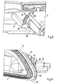
- eine Einzelheit X der Fig. 4 in größerer Darstellung,
- Fig. 9
- eine Einzelheit Y der Fig. 4 in größerer Darstellung.
- In den Fig. 1 bis 4 ist ein Karosserieteil 1 gezeigt, das zumindest eine Mulde 2 zur Aufnahme eines Bauteils 3 aufweist. Im Ausführungsbeispiel wird das Karosserieteil 1 durch ein aus elastischem Kunststoff gefertigtes Bugendteil eines Kraftfahrzeug gebildet. Das Karosserieteil 1 könnte jedoch auch durch ein Blechteil oder dgl. gebildet werden.
- Das Bauteil 3 wird im Ausführungsbeispiel durch eine langgestreckte in Fahrzeugquerrichtung verlaufende etwa horizontal ausgerichtete Zusatzleuchte gebildet, die einen Blinker und/oder eine Positionsleuchte und/oder eine Nebelleuchte oder dgl. enthält. Zumindest ein Teilbereich des Bauteils 3 könnte beispielsweise auch durch ein Lufteinlassteil, eine Blende oder dgl. gebildet werden.
Das Bauteil 3 besteht im Wesentlichen aus einem Gehäuse 4, das an seiner Vorderseite durch eine durchsichtige Scheibe 5 aus Glas oder Kunststoff geschlossen ist und das an seiner Rückseite Lampenfassungen 6 aufweist, in die Glühlampen 7 einsetzbar sind. - Die Mulde 2 ist im Ausführungsbeispiel einstückig mit dem Karosserieteil 1 ausgebildet und umfasst einen oberen Wandabschnitt 8, einen unteren Wandabschnitt 9, zwei gegenüberliegend angeordnete Seitenwandabschnitte 10, 11 und einen hinteren aufrecht verlaufenden Wandabschnitt 12. Im Ausführungsbeispiel sind der obere Wandabschnitt 8 und der untere Wandabschnitt 9 etwa horizontal ausgebildet. Der hintere in der Draufsicht gesehen bogenförmig verlaufende Wandabschnitt 12 erstreckt sich lediglich in einem mittleren Teilbereich der Quererstreckung der Mulde 2 und verbindet den oberen Wandabschnitt 8 mit dem unteren Wandabschnitt 9. Dadurch erfolgt eine Aussteifung der Mulde 2. Zu beiden Seiten des hinteren Wandabschnitts 12 sind großflächige Durchtrittsöffnungen 13 vorgesehen, durch die Teilbereiche des aufgenommenen Bauteils 3 hindurchragen. Durch die Formgebung des hinteren Wandabschnitts 12, der Durchtrittsöffnungen 13 und die korrespondierende Ausbildung des Gehäuses 4 des Bauteils 3 wird das lagerichtige Einführen des Bauteils 3 in die Mulde 2 des Karosserieteils 1 in Fahrzeugquerrichtung unterstützt. Im Ausführungsbeispiel ist die quer verlaufende Mulde 2 etwa horizontal ausgerichtet und die Schwenkachse 22 verläuft rechtwinkelig hierzu. Die Mulde 2 kann selbstverständlich auch aufrecht oder schräg verlaufend ausgerichtet sein.
- Das Bauteil 3 wird von der Außenseite des Kraftfahrzeuges her an die Mulde 2 herangeführt und über eine schräg verlaufende Einführstellung A in die Mulde 2 eingesetzt. Zur lagerichtigen Positionierung des Bauteils 3 in Höhenrichtung sind am Bauteil 3 und zwar an der Oberseite und an der Unterseite des Gehäuses 4 örtlich vorstehende Rippen ausgebildet, die sich mit ihren freien Enden an korrespondierenden ebenfalls vorstehenden Auflageflächen der Mulde 2 abstützen (nicht näher dargestellt). Dadurch wird beim Einsetzen des Bauteils 3 umlaufend ein gleichmäßiger Fugenverlauf 14 zwischen Mulde 2 und Bauteil 3 erzielt.
- Die Befestigungsvorrichtung 15 für das in der Mulde 2 aufgenommene Bauteil 3 besteht aus einem an einem seitlichen Randbereich 16 des Bauteils 3 angeformten Halteteil 17, das in der Betriebsstellung B des Bauteiles 3 mit einem ersten Seitenwandabschnitt 10 der Mulde 2 in Wirkverbindung steht. Ferner umfasst die Befestigungsvorrichtung 15 ein an einem gegenüberliegenden seitlichen Randbereich 18 des Bauteiles 3 angeordnetes federndes Rastteil 19, das in der Betriebsstellung B mit einem zweiten Seitenwandabschnitt 11 der Mulde 2 zusammenwirkt.
- Erfindungsgemäß ist zwischen der Mulde 2 und dem angrenzenden Bauteil 3 in einem oberen und/oder unteren Bereich 20 jeweils eine Einrichtung 21 zwischengeschaltet, die ein lagerichtiges Einführen des aufzunehmenden Bauteils 3 in die Mulde 2 und ein definiertes Verschwenken des Bauteils 3 um eine aufrechte Schwenkachse 22 in die Betriebsstellung B bewerkstelligt. Beim Verschwenken des Bauteils 3 in Pfeilrichtung C um die Schwenkachse 22 hintergreift das angeformte Halteteil 17 einen freien Randbereich 23 des ersten Seitenwandabschnitts 10, wogegen das federnde Rastteil 19 mit einem freien Randbereich 24 des zweiten Seitenwandabschnitts 11 verrastend zusammenwirkt (Fig. 7).
- Jede Einrichtung 21 setzt sich aus einer in Einschubrichtung D des Bauteils 3 hin offenen Aufnahme 25 und einem mit der Aufnahme 25 zusammenwirkenden Führungselement 26 zusammen. Im Ausführungsbeispiel sind die Aufnahmen 25 dem Karosserieteil 1 und die Führungselemente 26 dem Bauteil 3 zugeordnet. Selbstverständlich könnte auch eine kinematische Umkehr dieses Prinzips vorgesehen sein.
- Die Aufnahmen 25 sind vorzugsweise einstückig mit dem Karosserieteil 1 ausgebildet. Sie könnten jedoch auch durch separate Teile gebildet werden, die nachträglich mit dem Karosserieteil 1 verbunden sind.
- Die Führungselemente 26 sind vorzugsweise einstückig mit dem aufzunehmenden Bauteil 3 ausgebildet. Das Halteteil 17 und das federnde Rastteil 19 sind ebenfalls einstückig mit dem aufzunehmenden Bauteil 3 ausgebildet und werden durch angeformte Abschnitte des Gehäuses 4 gebildet. Die vorzugsweise am oberen Wandabschnitt 8 und am unteren Wandabschnitt 9 ausgebildeten Aufnahmen 25 sind in der Draufsicht gesehen jeweils etwa V-förmig ausgebildet, wobei die beiden seitlichen Schenkel 27, 28 jeder Aufnahme 25 über einen hinteren radienförmigen Übergangsbereich 29 miteinander verbunden sind. Durch die V-förmige Ausgestaltung der Aufnahme 25 wird das Einführen des Bauteils 3 in die Mulde 2 wesentlich erleichtert und erfolgt zwangsweise.
- Die am Gehäuse 4 des Bauteils 3 ausgebildeten nach unten bzw. oben hin vorstehenden Führungselemente 26 werden durch zylindrische Drehzapfen (nicht näher dargestellt) oder durch langgestreckte rippenartige Anformungen 30 gebildet, die an ihren den Aufnahmen 25 zugekehrten Enden in der Draufsicht gesehen halbkreisförmig oder kreisförmig ausgebildet sind. Bei der Montage des Bauteils 3 wird dieses soweit in die Mulde 2 eingeschoben, bis die halbkreisförmigen oder kreisförmigen Enden 31 oder die zylindrischen Drehzapfen am radienförmigen Übergangsbereich 29 der Aufnahmen 25 anliegen. Die in Höhenrichtung gesehen übereinander liegenden Mittelpunkte der zylindrischen Drehzapfen bzw. der halbkreisförmigen Enden der Führungselemente 26 sowie der Aufnahmen 25 definieren die Schwenkachse 22 des Bauteils 3.
- In der Draufsicht gesehen verläuft die Schwenkachse 22 des Bauteils 3 mit Abstand zu beiden Seitenwandabschnitten 10, 11 der Mulde 2 und zwar benachbart dem hinteren aufrechten Wandabschnitt 12 der Mulde 2.
- Das Halteteil 17 wird durch einen angespritzten, lang gestreckten schmalen Flansch 32 gebildet, der dem räumlichen Formverlauf des angrenzenden bogenförmigen Seitenwandabschnitts 10 angepasst ist. Das Halteteil 17 kann über seine gesamte Längserstreckung oder nur bereichsweise an erhaben ausgebildeten Auflageabschnitten 33 am stirnseitigen Wandbereich 23 des Seitenwandabschnitts 10 anliegen (Fig. 9). Das federnde Rastteil 19 umfasst im Ausführungsbeispiel zwei in Einschubrichtung D aneinander gesetzte Rasthaken 34, 35. In der Betriebsstellung B des Bauteils 3 hintergreift der weiter vorne liegende Rasthaken 34 den Randbereich 24 des Seitenwandabschnitts 11 der Mulde 2 (Fig. 7).
- Der in Einschubrichtung D weiter hinten liegende Rasthaken 35 stellt eine zusätzliche Sicherung gegen ungewolltes Herausfallen des Bauteils 3 dar, wenn die Rastverbindung zwischen Rasthaken 34 und dem Randbereich 24 gelöst wurde. Die Rastverbindung lässt sich ohne Zusatzwerkzeuge mittels einer Kreditkarte oder ähnlichem lösen, die in den Spalt 36 zwischen Bauteil 3 und Mulde 2 im Bereich des Rastteils 19 von außen her einführbar ist.
- Die Montage des Bauteils 3 erfolgt dergestalt. Das Bauteil 3 wird unter leichter Schrägstellung von vorne her an die Mulde 2 des Karosserieteils 1 herangeführt. Durch die Kontur des hinteren Wandabschnitts 12 der Mulde 2, die beiden seitlich daran anschließenden Durchtrittsöffnungen 13 und das korrespondierend ausgebildete Gehäuse 4 des aufzunehmenden Bauteils 3 wird das lagerichtige Einsetzen des Bauteils 3 in Querrichtung definiert.
- Gleichzeitig greifen die Führungselemente 26 des Bauteils 3 in die nach vorne hin offenen V-förmigen Aufnahmen 25 der Mulde 2 ein. Das Bauteil 3 wird solange in Einschubrichtung D bewegt, bis die Drehzapfen oder die kreisbogenförmigen Enden 31 der Führungselemente 26 am Grund der Aufnahme 25 anliegen. Danach erfolgt durch kurzen Druck auf das innere Ende 37 des Bauteils 3 ein Verschwenken um die aufrechte Schwenkachse 22 der Einrichtung 21. Gleichzeitig mit dem Verschwenken erfolgt eine Verrastung des Bauteils 3 an beiden seitlichen Endbereichen.
- Eine Demontage des Bauteils 3 erfolgt durch zweimaliges Einstecken einer Kreditkarte oder ähnlichem in den Spalt 36 zwischen dem Bauteil 3 und der Mulde 2 und zwar im Bereich des Rastteiles 19. Danach kann das Bauteil 3 aus der Mulde 2 entnommen werden. Beim ersten Einstecken der Kreditkarte wird die Verbindung zwischen dem vorderen Rasthaken 34 und dem Randbereich 24 des Seitenwandabschnitts 11 gelöst und das Bauteil 3 springt geringfügig nach außen vor, wird jedoch durch den zweiten Rasthaken 35 gegen Herausfallen gesichert.
Claims (12)
- Befestigungsvorrichtung für ein in einer Mulde (2) eines Karosserieteiles (1) aufgenommenes Bauteil (3), das von der Außenseite her über eine schräg verlaufende Montagestellung in die Mulde (2) einsetzbar und durch eine Schwenkbewegung in eine Betriebsstellung innerhalb der Mulde (2) verlagerbar ist, wobei die Mulde (2) zwei Seiten wandabschnitte (10, 11) und zwei mit Abstand zueinander angeordnete Wandabschnitte (8, 9) aufweist und wobei in der Betriebsstellung ein an einem ersten Randbereich des Bauteiles (3) angeformtes Halteteil (17) mit einem ersten Seitenwandabschnitt (10) der Mulde (2) in Wirkverbindung steht und an einem gegenüberliegenden zweiten Randbereich des Bauteiles (3) ein federndes Rastteil (19) vorgesehen ist, das mit einem zweiten Seitenwandabschnitt (11) der Mulde (2) zusammenwirkt (2) dadurch gekennzeichnet, dass zwischen der Mulde (2) und dem angrenzenden Bauteil (3) im Bereich beider Wandabschnitte (8, 9) jeweils eine Einrichtung (21) zwischengeschaltet ist, die ein lagerichtiges Einführen des aufzunehmenden Bauteils (3) in die Mulde (2) und ein definiertes Verschwenken des Bauteils (3) um eine etwa rechtwinkelig zu den Wandabschnitten (8, 9) verlaufende Schwenkachse (22) in die Betriebsstellung (B) bewerkstelligt, wobei beim Verschwenken des Bauteils (3) das angeformte Halteteil (17) einen freien Randbereich (23) des ersten Seitenwandabschnitts (10) hintergreift, wogegen das federnde Rastteil (19) mit einem freien Randbereich (24) des zweiten Seitenwandabschnitts (11) verrastend zusammenwirkt.
- Befestigungsvorrichtung nach Anspruch 1, dadurch gekennzeichnet, dass sich jede Einrichtung (21) aus einer in Einschubrichtung (D) des Bauteils (3) hin offenen Aufnahme (25) und einem mit der Aufnahme (25) zusammenwirkenden Führungselement (26) zusammensetzt.
- Befestigungsvorrichtung nach Anspruch 2, dadurch gekennzeichnet, dass die Aufnahmen (25) dem Karosserieteil (1) und die Führungselemente (26) dem Bauteil (3) zugeordnet sind oder umgekehrt.
- Befestigungsvorrichtung nach Anspruch 2 oder 3, dadurch gekennzeichnet, dass die Aufnahmen (25) einstückig mit dem Karosserieteil (1) ausgebildet sind.
- Befestigungsvorrichtung nach den Ansprüchen 2 oder 3, dadurch gekennzeichnet, dass die Führungselemente (26) einstückig mit dem aufzunehmenden Bauteil (3) ausgebildet sind.
- Befestigungsvorrichtung nach Anspruch 1, dadurch gekennzeichnet, dass das zumindest eine Halteteil (17) und das federnde Rastteil (19) ebenfalls einstückig mit dem aufzunehmenden Bauteil (3) ausgebildet sind.
- Befestigungsvorrichtung nach Anspruch 2, dadurch gekennzeichnet, dass die obere und/oder untere Aufnahme (25) in der Draufsicht gesehen jeweils etwa V-förmig ausgebildet sind, wobei die beiden Schenkel (27, 28) jeder Aufnahme (25) über einen hinteren radienförmigen Übergangsbereich (29) miteinander verbunden sind.
- Befestigungselement nach Anspruch 2, dadurch gekennzeichnet, dass die vorstehenden Führungselemente (26) durch zylindrische Drehzapfen oder durch langgestreckte rippenartige Anformungen (30) gebildet werden, die an ihren den Aufnahmen (25) zugekehrten Enden (31) in der Draufsicht gesehen halbkreisförmig ausgebildet sind.
- Befestigungsvorrichtung nach einem der vorangegangenen Ansprüche, dadurch gekennzeichnet, dass das Halteteil (17) durch einen langgestreckten Flansch (32) gebildet ist, der dem räumlichen Formverlauf des angrenzenden Seitenwandabschnittes (11) angepasst ist.
- Befestigungsvorrichtung nach einem der vorangegangenen Ansprüche, dadurch gekennzeichnet, dass das federnde Rastteil (19) zwei in Einschubrichtung (D) aneinander gesetzte Rasthaken (34, 35) umfasst, wobei der in Einschubrichtung (D) vordere Rasthaken (34) die Betriebsstellung (B) des Bauteils (3) definiert, wogegen der in Einschubrichtung (D) hintere Rasthaken (35) eine Sicherung gegen ungewolltes Herausfallen des Bauteils (3) darstellt.
- Befestigungsvorrichtung nach einem der vorangegangenen Ansprüche, dadurch gekennzeichnet, dass zur lagerichtigen Positionierung des Bauteils (3) in Höhenrichtung am Bauteil (3) örtlich vorstehende Rippen und an der Mulde (2) örtlich korrespondierende Auflageflächen ausgebildet sind, wobei sich die Rippen mit ihren freien Enden an den Auflageflächen abstützen.
- Befestigungsvorrichtung nach einem der vorangegangenen Ansprüche dadurch gekennzeichnet, dass die Schwenkachse (22) des Bauteils (3) in der Draufsicht gesehen mit Abstand zu den beiden Seitenwandabschnitten (10, 11) der Mulde (2) verläuft.
Applications Claiming Priority (2)
| Application Number | Priority Date | Filing Date | Title |
|---|---|---|---|
| DE10342168.8A DE10342168B4 (de) | 2003-09-12 | 2003-09-12 | Befestigungsvorrichtung für ein in einer Mulde eines Karosserieteiles aufgenommenes Bauteil |
| DE10342168 | 2003-09-12 |
Publications (2)
| Publication Number | Publication Date |
|---|---|
| EP1514771A1 EP1514771A1 (de) | 2005-03-16 |
| EP1514771B1 true EP1514771B1 (de) | 2007-08-22 |
Family
ID=34129783
Family Applications (1)
| Application Number | Title | Priority Date | Filing Date |
|---|---|---|---|
| EP04017187A Expired - Lifetime EP1514771B1 (de) | 2003-09-12 | 2004-07-21 | Befestigungsvorrichtung für ein in einer Mulde eines Karosserieteiles aufgenommenes Bauteil |
Country Status (4)
| Country | Link |
|---|---|
| US (1) | US7014254B2 (de) |
| EP (1) | EP1514771B1 (de) |
| DE (2) | DE10342168B4 (de) |
| ES (1) | ES2289400T3 (de) |
Families Citing this family (13)
| Publication number | Priority date | Publication date | Assignee | Title |
|---|---|---|---|---|
| GB2439959B (en) * | 2006-07-06 | 2011-11-09 | Nissan Motor Mfg | Improvements relating to mountings for vehicle fog lamps |
| US20090168443A1 (en) * | 2007-12-27 | 2009-07-02 | Toyota Motor Engineering & Manufacturing North America, Inc. | Reduced Glare Fog Lamp Assembly |
| US7784982B2 (en) * | 2008-03-12 | 2010-08-31 | Nissan Technical Center North America, Inc. | Wraparound light assembly |
| DE102008017896A1 (de) | 2008-04-09 | 2009-10-15 | Dr. Ing. H.C. F. Porsche Aktiengesellschaft | Frontbugteil eines Kraftfahrzeugs mit einem Luftführungselement |
| US20110032719A1 (en) * | 2009-08-05 | 2011-02-10 | Toyota Motor Engineering & Manufacturing North America, Inc. | Control device for controlling the position of a bumper fascia |
| DE102012103417B4 (de) * | 2012-04-19 | 2025-08-07 | Dr. Ing. H.C. F. Porsche Aktiengesellschaft | Einrichtung zum Fixieren eines Bugteils an einem Kotflügel bei einem Kraftfahrzeug |
| US10272819B2 (en) * | 2017-01-04 | 2019-04-30 | Ford Global Technologies, Llc | Loose layered build components and vehicle front end assembly strategy |
| US10450018B2 (en) | 2017-01-04 | 2019-10-22 | Ford Global Technologies, Llc | Loose layered build components and vehicle front end assembly strategy |
| US10704756B2 (en) | 2017-01-04 | 2020-07-07 | Ford Global Technologies, Llc | Loose layered build components and vehicle front end assembly strategy |
| DE102017126679B4 (de) | 2017-11-14 | 2024-09-19 | Dr. Ing. H.C. F. Porsche Aktiengesellschaft | Kraftfahrzeug mit einer Karosserie und einem in eine Aufnahmeöffnung der Karosserie eingesetzten Bauteil |
| DE102018131913B4 (de) * | 2018-12-12 | 2026-01-08 | Volkswagen Aktiengesellschaft | Heckspoiler |
| FR3121885A1 (fr) * | 2021-04-15 | 2022-10-21 | Psa Automobiles Sa | Pare-chocs de véhicule terrestre à bloc(s) optique(s) extractible(s)/installable(s) par la face avant |
| DE102023114391A1 (de) * | 2023-06-01 | 2024-12-05 | Dr. Ing. H.C. F. Porsche Aktiengesellschaft | Verfahren zur Montage eines Ladeschnittstellenmoduls eines Elektrofahrzeugs und Ladeschnittstelleneinheit eines Elektrofahrzeugs |
Family Cites Families (20)
| Publication number | Priority date | Publication date | Assignee | Title |
|---|---|---|---|---|
| DE3044313C2 (de) * | 1980-11-25 | 1984-07-19 | Ford-Werke AG, 5000 Köln | Befestigungsvorrichtung für in Mulden von Karosserieteilen aufgenommene Bauteile |
| DE3402274A1 (de) * | 1984-01-24 | 1985-08-01 | Bosch Gmbh Robert | Scheinwerfer fuer fahrzeuge, insbesondere fuer kraftfahrzeuge |
| DE3439234C1 (de) * | 1984-10-26 | 1986-03-06 | Westfaelische Metall Industrie | Vorrichtung zur Befestigung eines Bauteils, insbesondere Fahrzeugleuchte, in der Mulde eines Karosserieteils |
| IT221656Z2 (it) * | 1989-10-13 | 1994-07-25 | Iveco Fiat | Elemento di carrozzeria di un veicolo incorporante un dispositivo di illuminazione. |
| JPH06283002A (ja) * | 1993-03-26 | 1994-10-07 | Koito Mfg Co Ltd | 自動車用ヘッドランプ |
| JP2965849B2 (ja) * | 1994-03-09 | 1999-10-18 | 株式会社小糸製作所 | 車両用灯具 |
| US5546284A (en) * | 1994-04-19 | 1996-08-13 | Koito Manufacturing Co., Ltd. | Automobile headlamp with extension reflector mounted on the front lense |
| JP3020135B2 (ja) * | 1995-01-26 | 2000-03-15 | 株式会社小糸製作所 | 自動車用前照灯 |
| JP3193603B2 (ja) * | 1995-12-25 | 2001-07-30 | 株式会社小糸製作所 | 車両用前照灯 |
| JPH10199305A (ja) * | 1997-01-10 | 1998-07-31 | Koito Mfg Co Ltd | 投射型ランプ |
| FR2775230B1 (fr) * | 1998-02-23 | 2000-05-12 | Valeo Vision | Ensemble perfectionne d'au moins un projecteur et d'un feu de signalisation, pour vehicule automobile |
| BR9906634A (pt) * | 1998-07-31 | 2000-08-01 | Plastic Omnium Cie | Sistema ótico para veìculo automotivo |
| JP2000118291A (ja) * | 1998-10-15 | 2000-04-25 | Stanley Electric Co Ltd | 車両用灯具の車体取付手段 |
| IT1307007B1 (it) * | 1999-01-26 | 2001-10-11 | Magneti Marelli Climat Srl | Gruppo frontale preassemblato per veicoli. |
| JP4345041B2 (ja) * | 2000-02-07 | 2009-10-14 | マツダ株式会社 | 車両用灯具 |
| JP2002193023A (ja) * | 2000-12-28 | 2002-07-10 | Koito Mfg Co Ltd | リフレクター可動型自動車用ヘッドランプ |
| DE10137842B4 (de) * | 2001-08-02 | 2005-06-16 | Visteon Global Technologies, Inc., Dearborn | Bauteil zur Aufnahme in ein Karosserieteil, insbesondere Leuchte |
| JP3577018B2 (ja) * | 2001-08-31 | 2004-10-13 | 本田技研工業株式会社 | 車両のフロントグリル周りの吸気構造 |
| JP2003178609A (ja) * | 2001-12-07 | 2003-06-27 | Ichikoh Ind Ltd | 車両用前照灯 |
| JP4070190B2 (ja) * | 2002-08-19 | 2008-04-02 | 株式会社小糸製作所 | 車両用ヘッドランプ |
-
2003
- 2003-09-12 DE DE10342168.8A patent/DE10342168B4/de not_active Expired - Fee Related
-
2004
- 2004-07-21 EP EP04017187A patent/EP1514771B1/de not_active Expired - Lifetime
- 2004-07-21 ES ES04017187T patent/ES2289400T3/es not_active Expired - Lifetime
- 2004-07-21 DE DE502004004709T patent/DE502004004709D1/de not_active Expired - Lifetime
- 2004-09-13 US US10/938,619 patent/US7014254B2/en not_active Expired - Fee Related
Also Published As
| Publication number | Publication date |
|---|---|
| DE10342168A1 (de) | 2005-05-04 |
| DE502004004709D1 (de) | 2007-10-04 |
| US7014254B2 (en) | 2006-03-21 |
| US20050057057A1 (en) | 2005-03-17 |
| DE10342168B4 (de) | 2015-11-19 |
| ES2289400T3 (es) | 2008-02-01 |
| EP1514771A1 (de) | 2005-03-16 |
Similar Documents
| Publication | Publication Date | Title |
|---|---|---|
| DE10203054B4 (de) | Frontgrillkonstruktion | |
| DE60212246T2 (de) | Gruppe von zwei Karosserieteilen die Kante an Kante zusammenzufügen sind und Karosserieteil aus einer solchen Bauteilgruppe | |
| DE3523909C2 (de) | ||
| EP0825051B1 (de) | Windschott für ein Cabriolet | |
| DE10342168B4 (de) | Befestigungsvorrichtung für ein in einer Mulde eines Karosserieteiles aufgenommenes Bauteil | |
| DE3446916C2 (de) | ||
| EP1544047A1 (de) | Fahrzeugkarosserie | |
| EP1294596A1 (de) | Scheibenwischer für kraftfahrzeuge | |
| DE10118111A1 (de) | Gurteinfügungsteil | |
| DE19632352B4 (de) | Windschott für ein Cabriolet | |
| DE4442294C1 (de) | Befestigungsanordnung zum Anbringen einer Fahrzeugleuchte in einem sie aufnehmenden Verkleidungsteil | |
| DE10326883A1 (de) | Pompadourtasche | |
| EP0796183A1 (de) | Koppelglied für eine scheibenwischeranlage, insbesondere eines kraftfahrzeuges | |
| DE60129878T2 (de) | Beleuchtungs- oder Signaleinrichtung für Fahrzeuge mit erhöhter Hitzebeständigkeit | |
| DE60009465T2 (de) | Vorrichtung zur befestigung einer an einer stossstange integrierten kotflügelverbreiterung | |
| EP1291255A2 (de) | Vorrichtung zur Aufnahme einer Fahrzeughubeinrichtung | |
| EP0062229B1 (de) | Gegenlagerböckchen für Fahrzeugsonnenblenden | |
| DE69401841T2 (de) | Befestigungseinrichtung für zwei Beleuchtungs- oder Signalvorrichtungen eines Fahrzeuges | |
| DE10353374A1 (de) | Befestigungsanordnung für einen Scheinwerfer an einem Fahrzeug | |
| DE4140362C2 (de) | Kraftfahrzeugleuchte | |
| EP0894663B1 (de) | Befestigungsanordnung einer Beleuchtungseinrichtung an einem Fahrzeug | |
| DE4238285C2 (de) | Scheinwerfer-Leuchten-Einheit für Fahrzeuge | |
| DE102020118080B4 (de) | Haltevorrichtung | |
| DE102016207179B3 (de) | Kraftfahrzeug-Tür und Türgriffsystem hierfür | |
| DE4438491C1 (de) | Leuchte für Fahrzeuge |
Legal Events
| Date | Code | Title | Description |
|---|---|---|---|
| PUAI | Public reference made under article 153(3) epc to a published international application that has entered the european phase |
Free format text: ORIGINAL CODE: 0009012 |
|
| AK | Designated contracting states |
Kind code of ref document: A1 Designated state(s): AT BE BG CH CY CZ DE DK EE ES FI FR GB GR HU IE IT LI LU MC NL PL PT RO SE SI SK TR |
|
| AX | Request for extension of the european patent |
Extension state: AL HR LT LV MK |
|
| 17P | Request for examination filed |
Effective date: 20050916 |
|
| AKX | Designation fees paid |
Designated state(s): DE ES FR GB IT |
|
| GRAP | Despatch of communication of intention to grant a patent |
Free format text: ORIGINAL CODE: EPIDOSNIGR1 |
|
| GRAS | Grant fee paid |
Free format text: ORIGINAL CODE: EPIDOSNIGR3 |
|
| GRAA | (expected) grant |
Free format text: ORIGINAL CODE: 0009210 |
|
| AK | Designated contracting states |
Kind code of ref document: B1 Designated state(s): DE ES FR GB IT |
|
| REG | Reference to a national code |
Ref country code: GB Ref legal event code: FG4D Free format text: NOT ENGLISH |
|
| REF | Corresponds to: |
Ref document number: 502004004709 Country of ref document: DE Date of ref document: 20071004 Kind code of ref document: P |
|
| GBT | Gb: translation of ep patent filed (gb section 77(6)(a)/1977) |
Effective date: 20071122 |
|
| ET | Fr: translation filed | ||
| REG | Reference to a national code |
Ref country code: ES Ref legal event code: FG2A Ref document number: 2289400 Country of ref document: ES Kind code of ref document: T3 |
|
| PLBE | No opposition filed within time limit |
Free format text: ORIGINAL CODE: 0009261 |
|
| STAA | Information on the status of an ep patent application or granted ep patent |
Free format text: STATUS: NO OPPOSITION FILED WITHIN TIME LIMIT |
|
| 26N | No opposition filed |
Effective date: 20080526 |
|
| REG | Reference to a national code |
Ref country code: FR Ref legal event code: TP |
|
| REG | Reference to a national code |
Ref country code: FR Ref legal event code: CD |
|
| PGFP | Annual fee paid to national office [announced via postgrant information from national office to epo] |
Ref country code: ES Payment date: 20100726 Year of fee payment: 7 |
|
| REG | Reference to a national code |
Ref country code: FR Ref legal event code: TP |
|
| REG | Reference to a national code |
Ref country code: GB Ref legal event code: 732E Free format text: REGISTERED BETWEEN 20110310 AND 20110316 |
|
| REG | Reference to a national code |
Ref country code: GB Ref legal event code: 732E Free format text: REGISTERED BETWEEN 20110331 AND 20110406 |
|
| REG | Reference to a national code |
Ref country code: ES Ref legal event code: FD2A Effective date: 20130604 |
|
| PG25 | Lapsed in a contracting state [announced via postgrant information from national office to epo] |
Ref country code: ES Free format text: LAPSE BECAUSE OF NON-PAYMENT OF DUE FEES Effective date: 20110722 |
|
| REG | Reference to a national code |
Ref country code: FR Ref legal event code: PLFP Year of fee payment: 13 |
|
| REG | Reference to a national code |
Ref country code: FR Ref legal event code: PLFP Year of fee payment: 14 |
|
| REG | Reference to a national code |
Ref country code: FR Ref legal event code: PLFP Year of fee payment: 15 |
|
| PGFP | Annual fee paid to national office [announced via postgrant information from national office to epo] |
Ref country code: MC Payment date: 20180829 Year of fee payment: 8 Ref country code: FR Payment date: 20180725 Year of fee payment: 15 |
|
| PGFP | Annual fee paid to national office [announced via postgrant information from national office to epo] |
Ref country code: GB Payment date: 20180719 Year of fee payment: 15 |
|
| GBPC | Gb: european patent ceased through non-payment of renewal fee |
Effective date: 20190721 |
|
| PG25 | Lapsed in a contracting state [announced via postgrant information from national office to epo] |
Ref country code: GB Free format text: LAPSE BECAUSE OF NON-PAYMENT OF DUE FEES Effective date: 20190721 |
|
| PG25 | Lapsed in a contracting state [announced via postgrant information from national office to epo] |
Ref country code: FR Free format text: LAPSE BECAUSE OF NON-PAYMENT OF DUE FEES Effective date: 20190731 |
|
| PG25 | Lapsed in a contracting state [announced via postgrant information from national office to epo] |
Ref country code: IT Free format text: LAPSE BECAUSE OF NON-PAYMENT OF DUE FEES Effective date: 20190721 |
|
| PGFP | Annual fee paid to national office [announced via postgrant information from national office to epo] |
Ref country code: DE Payment date: 20210705 Year of fee payment: 18 |
|
| REG | Reference to a national code |
Ref country code: DE Ref legal event code: R119 Ref document number: 502004004709 Country of ref document: DE |
|
| PG25 | Lapsed in a contracting state [announced via postgrant information from national office to epo] |
Ref country code: DE Free format text: LAPSE BECAUSE OF NON-PAYMENT OF DUE FEES Effective date: 20230201 |