EP1513101A1 - Fahrhilfesystem - Google Patents
Fahrhilfesystem Download PDFInfo
- Publication number
- EP1513101A1 EP1513101A1 EP03730616A EP03730616A EP1513101A1 EP 1513101 A1 EP1513101 A1 EP 1513101A1 EP 03730616 A EP03730616 A EP 03730616A EP 03730616 A EP03730616 A EP 03730616A EP 1513101 A1 EP1513101 A1 EP 1513101A1
- Authority
- EP
- European Patent Office
- Prior art keywords
- image
- vehicle
- dimensional projection
- model
- driving assistance
- Prior art date
- Legal status (The legal status is an assumption and is not a legal conclusion. Google has not performed a legal analysis and makes no representation as to the accuracy of the status listed.)
- Withdrawn
Links
- 238000003384 imaging method Methods 0.000 claims abstract description 22
- 238000013519 translation Methods 0.000 claims abstract description 18
- 238000013507 mapping Methods 0.000 claims description 12
- 230000002194 synthesizing effect Effects 0.000 description 16
- 230000015654 memory Effects 0.000 description 10
- 238000000034 method Methods 0.000 description 5
- 230000008569 process Effects 0.000 description 5
- 239000007787 solid Substances 0.000 description 3
- 230000008901 benefit Effects 0.000 description 2
- 238000012544 monitoring process Methods 0.000 description 2
- 230000015572 biosynthetic process Effects 0.000 description 1
- 230000000694 effects Effects 0.000 description 1
- 238000009434 installation Methods 0.000 description 1
- 238000012986 modification Methods 0.000 description 1
- 230000004048 modification Effects 0.000 description 1
- 230000004044 response Effects 0.000 description 1
- 230000007480 spreading Effects 0.000 description 1
Images


Classifications
-
- B—PERFORMING OPERATIONS; TRANSPORTING
- B60—VEHICLES IN GENERAL
- B60R—VEHICLES, VEHICLE FITTINGS, OR VEHICLE PARTS, NOT OTHERWISE PROVIDED FOR
- B60R21/00—Arrangements or fittings on vehicles for protecting or preventing injuries to occupants or pedestrians in case of accidents or other traffic risks
-
- G06T3/047—
-
- B—PERFORMING OPERATIONS; TRANSPORTING
- B60—VEHICLES IN GENERAL
- B60R—VEHICLES, VEHICLE FITTINGS, OR VEHICLE PARTS, NOT OTHERWISE PROVIDED FOR
- B60R1/00—Optical viewing arrangements; Real-time viewing arrangements for drivers or passengers using optical image capturing systems, e.g. cameras or video systems specially adapted for use in or on vehicles
- B60R1/20—Real-time viewing arrangements for drivers or passengers using optical image capturing systems, e.g. cameras or video systems specially adapted for use in or on vehicles
- B60R1/22—Real-time viewing arrangements for drivers or passengers using optical image capturing systems, e.g. cameras or video systems specially adapted for use in or on vehicles for viewing an area outside the vehicle, e.g. the exterior of the vehicle
- B60R1/23—Real-time viewing arrangements for drivers or passengers using optical image capturing systems, e.g. cameras or video systems specially adapted for use in or on vehicles for viewing an area outside the vehicle, e.g. the exterior of the vehicle with a predetermined field of view
- B60R1/26—Real-time viewing arrangements for drivers or passengers using optical image capturing systems, e.g. cameras or video systems specially adapted for use in or on vehicles for viewing an area outside the vehicle, e.g. the exterior of the vehicle with a predetermined field of view to the rear of the vehicle
-
- G—PHYSICS
- G06—COMPUTING; CALCULATING OR COUNTING
- G06T—IMAGE DATA PROCESSING OR GENERATION, IN GENERAL
- G06T15/00—3D [Three Dimensional] image rendering
-
- G—PHYSICS
- G06—COMPUTING; CALCULATING OR COUNTING
- G06T—IMAGE DATA PROCESSING OR GENERATION, IN GENERAL
- G06T3/00—Geometric image transformation in the plane of the image
-
- G06T5/80—
-
- B—PERFORMING OPERATIONS; TRANSPORTING
- B60—VEHICLES IN GENERAL
- B60G—VEHICLE SUSPENSION ARRANGEMENTS
- B60G2400/00—Indexing codes relating to detected, measured or calculated conditions or factors
- B60G2400/80—Exterior conditions
- B60G2400/82—Ground surface
- B60G2400/821—Uneven, rough road sensing affecting vehicle body vibration
-
- B—PERFORMING OPERATIONS; TRANSPORTING
- B60—VEHICLES IN GENERAL
- B60G—VEHICLE SUSPENSION ARRANGEMENTS
- B60G2400/00—Indexing codes relating to detected, measured or calculated conditions or factors
- B60G2400/80—Exterior conditions
- B60G2400/82—Ground surface
- B60G2400/823—Obstacle sensing
-
- B—PERFORMING OPERATIONS; TRANSPORTING
- B60—VEHICLES IN GENERAL
- B60G—VEHICLE SUSPENSION ARRANGEMENTS
- B60G2400/00—Indexing codes relating to detected, measured or calculated conditions or factors
- B60G2400/80—Exterior conditions
- B60G2400/82—Ground surface
- B60G2400/824—Travel path sensing; Track monitoring
-
- B—PERFORMING OPERATIONS; TRANSPORTING
- B60—VEHICLES IN GENERAL
- B60G—VEHICLE SUSPENSION ARRANGEMENTS
- B60G2401/00—Indexing codes relating to the type of sensors based on the principle of their operation
- B60G2401/14—Photo or light sensitive means, e.g. Infrared
- B60G2401/142—Visual Display Camera, e.g. LCD
-
- B—PERFORMING OPERATIONS; TRANSPORTING
- B60—VEHICLES IN GENERAL
- B60R—VEHICLES, VEHICLE FITTINGS, OR VEHICLE PARTS, NOT OTHERWISE PROVIDED FOR
- B60R2300/00—Details of viewing arrangements using cameras and displays, specially adapted for use in a vehicle
- B60R2300/10—Details of viewing arrangements using cameras and displays, specially adapted for use in a vehicle characterised by the type of camera system used
- B60R2300/105—Details of viewing arrangements using cameras and displays, specially adapted for use in a vehicle characterised by the type of camera system used using multiple cameras
-
- B—PERFORMING OPERATIONS; TRANSPORTING
- B60—VEHICLES IN GENERAL
- B60R—VEHICLES, VEHICLE FITTINGS, OR VEHICLE PARTS, NOT OTHERWISE PROVIDED FOR
- B60R2300/00—Details of viewing arrangements using cameras and displays, specially adapted for use in a vehicle
- B60R2300/30—Details of viewing arrangements using cameras and displays, specially adapted for use in a vehicle characterised by the type of image processing
-
- B—PERFORMING OPERATIONS; TRANSPORTING
- B60—VEHICLES IN GENERAL
- B60R—VEHICLES, VEHICLE FITTINGS, OR VEHICLE PARTS, NOT OTHERWISE PROVIDED FOR
- B60R2300/00—Details of viewing arrangements using cameras and displays, specially adapted for use in a vehicle
- B60R2300/60—Details of viewing arrangements using cameras and displays, specially adapted for use in a vehicle characterised by monitoring and displaying vehicle exterior scenes from a transformed perspective
Definitions
- the present invention relates to a driving assistance system which assists when a vehicle backs by displaying a vehicle rear-side image picked up by a camera equipped with the vehicle on a monitor equipped with the vehicle and, more particularly, to a driving assistance system which displays a less distorted image on the equipped monitor thereby not causing a driver to feel a sense of incompatibility.
- a driving assistance system which installs an equipped camera backward in a rear trunk portion or the like of a vehicle and provides an image of a rear side of the vehicle picked up by the equipped camera to the driver is spreading nowadays.
- Some of the driving assistance systems translates/synthesizes a real image picked up the equipped camera into an image that looks as if such image is picked up from a viewpoint being set virtually and displays a resultant image on a monitor, and the driving assistance systems are mainly used for the purpose of the safety check and the parking assistance in backing the vehicle.
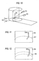
- a three-dimensional projection model 100 configured to have a cylindrical surface model 101 and a flat surface model 102 is used. Then, a real image picked up by a real camera 103 is translated/synthesized into an image viewed from a virtual camera 104, and then is displayed as an image projected onto the three-dimensional projection model 100 on an equipped monitor.
- FIG.11 is an explanatory view showing an image obtained by projecting a straight line 105 shown in FIG.10 onto the three-dimensional projection model 100.
- a straight line image 105a on a monitor screen 106 is displayed to be folded at a model boundary 107 between the cylindrical surface model 101 and the flat surface model 102.
- the reason for that originally straight line 105 is translated as a folded image 105a when the three-dimensional projection model 100 configured to combine the cylindrical surface onto which the far image is projected and the flat surface onto which the near image is projected is used is that distortion of the display is concentrated onto the model boundary 107 between two three-dimensional projection models 101, 102.
- the driver looks at this folded image 105a, he or she perceives a sense of incompatibility.
- This three-dimensional projection model 200 is configured to have the cylindrical surface 101 onto which the far image is projected, and a spherical surface model 201 which is successively connected to this surface and onto which the near image is projected.
- the spherical surface model 201 is used as the model on which the picked-up image near the vehicle is projected, an overall projected image on the spherical surface model 201 changes smoothly and therefore a sense of incompatibility of the driver can be considerably relaxed.
- the picked-up image near the vehicle is never distorted at the particular portion concentrated, but it occurs a problem that the distortion is generated in the overall image.
- the image obtained by picking up an image of a lattice pattern on the ground 202 by the real camera 103 and then projecting the picked-up image onto the spherical surface model 201 is distorted as a whole, as shown in FIG.14. That is, there is a problem such that a group of straight lines constituting originally a lattice on the ground 202 are displayed as a group of curved lines on the screen 106, and it is difficult to grasp positional relationships between the driver's own vehicle and the surroundings based on such image.
- An object of the present invention is to provide a driving assistance system in which a three-dimensional projection model capable of monitoring/displaying a surrounding image of a vehicle as a less distorted image while suppressing incompatibility with a distant image from the vehicle is installed.
- a driving assistance system of the present invention has imaging means for picking up a surrounding image of a vehicle on a road surface; image translating means for executing an image translation by using a three-dimensional projection model, in which a shape on a side of the road surface is convex and a height from the road surface does not vary within a predetermined range from a top end portion of the vehicle in a traveling direction, to translate the image picked up by the imaging means into an image viewed from a virtual viewpoint; and displaying means for displaying an image translated by the image translating means.
- the straight line such as the box of the parking lot, or the like depicted in parallel with the traveling direction of the vehicle on the road surface near the vehicle is displayed as the straight line on the screen of the displaying means, and thus it becomes easy to grasp the relative positional relationship between the driver's own vehicle and the surroundings.
- a projection surface that gradually gets up from the road surface in a range extending beyond the predetermined range in a width direction of the vehicle is continuously provided in the three-dimensional projection model. According to this configuration, the picked-up image in a wide range in the width direction of the vehicle can be displayed on the screen not to make the image distortion prominent.
- a projection surface that gradually gets up from the road surface in a range extending beyond the predetermined range in the traveling direction of the vehicle is continuously provided in the three-dimensional projection model. According to this configuration, the picked-up image in a wide range in the traveling direction of the vehicle can be displayed on the screen not to make the image distortion prominent.
- the three-dimensional projection model is formed by successive curved surfaces that can be differentiated in a full range except end points. According to this configuration, no discontinuous singular point is present on the screen, and a sense of incompatibility caused by connecting a plurality of three-dimensional models (the cylindrical surface and the spherical surface) is not generated. Also, a scale factor or a distortion can be varied on the screen by adjusting an inclination of the convex surface, and thus a sense of distance and a sense of direction on the screen can be adjusted by utilizing this. In addition, since all three-dimensional models are a smooth curved surface that is convex downward, the image distortion is not concentrated into a particular portion but dispersed over the entire screen to provide a clear screen. Therefore, the image by which the driver easily grasps the sense of distance and from which the driver does not feel a sense of incompatibility can be provided to the driver.
- the three-dimensional projection model has a cylindrical surface which shape on the side of the road surface is convex, and a spherical surface which is smoothly connected to an end portion of the cylindrical surface.
- the three-dimensional projection models can be represented by equations, and thus the image translating process and formation of the mapping table can be made easy.
- the predetermined range is projected onto the cylindrical surface to has a length in the traveling direction of the vehicle, which is set to 120 % or less of 5 m that is a length of a normal box of a parking lot, and a width, which is set to a range of 80 % to 120 % of 3 m that is a width of the normal box of the parking lot.
- the screen that is suited to the parking operations can be provided to the driver.
- the cylindrical surface is a cylindrical surface of an ellipse, and the ellipse whose ratio of a maximum width and a minimum width between equal-interval lattice lines, which are in parallel with a center axis of the cylindrical surface on the road surface projected onto the cylindrical surface, is at least 80 % in the predetermined range is used as the three-dimensional projection model. According to this configuration, the screen that has a small distortion can be provided to the driver.
- the three-dimensional projection model and a position of the virtual viewpoint are set such that both left and right ends of a rear end image of the vehicle displayed on a screen of the displaying means enter into an at least 15 % range of a screen width from both end positions of the screen. According to this configuration, the image of the blind spot position, which cannot be directly viewed by the driver, is displayed largely on the screen, and thus the driver can drive with a sense of security.
- the three-dimensional projection model and a position of the virtual viewpoint are set such that a linear shape of a rear end of the vehicle in the predetermined range is displayed as a linear image on the screen of the displaying means.
- the driver can easily confirm a shape of a bumper, etc. of the driver's own vehicle, and the driver can exactly grasped the positional relationship between the road surface and the driver's own vehicle.
- positions of the three-dimensional projection model and the virtual viewpoint are set such that left and right both ends of the rear end image of the vehicle displayed on the screen on the displaying means enter into an at least 15% range off the screen width from both end positions of the screen, the image of the rear portion of the vehicle such as the bumper, etc., which is displayed larger than a width of the vehicle on the road surface on the screen obtained by the viewing translation, is cut off to have an appropriate width in response to the width of the screen and then displayed. Therefore, it is possible to reduce a factor of the sense of incompatibility such that a width of the vehicle on the road surface and a width of the bumper are largely differently displayed.
- a guide line indicating a straight line on the road surface which is in parallel with the traveling direction of the vehicle and indicates an outer side that is outer than the width of the vehicle by a predetermined value, is superposed on an image translated by using the three-dimensional projection model and to display on the screen of the displaying means.
- the driver can intuitively catch the relative positional relationship between the guide line and the straight line on the road surface from the screen, and thus the operation of aligning the position to the mark such as the side line of the box of the parking lot, the road surface, etc. in the parking is made easy.
- the image translating means translates the picked-up image by using a mapping table in which a translation address based on the three-dimensional projection model is stored. According to this configuration, it is not required to execute the computing process by using the three-dimensional projection model every time, and thus the image translating process can be carried out at a high speed.
- a reference numeral 1 is an own vehicle, 1a is a bumper image, 2 is an imaging device, 3 is an image synthesizing translating system, 4 is a display device (monitor), 10 is a distance-indicating guide line, 11 is a width indicating guide line, 12 is a linear guide line on a road surface, 21, 23 are cameras, 22, 24 are frame memories, 31 is an image synthesizing means, 32 is a mapping table looking-up means, 32a is a translation address memory, 32b is a degree-of-necessity memory, 33 is an image signal generating means, 300 is a three-dimensional projection model, 301 is a cylindrical surface model (ellipse), 302 is a spherical surface model (ellipse), 506 is a flat surface model, and 521, 522 are cylindrical surface models.
- FIG.1 is a configurative view showing a fitting of a driving assistance system according to an embodiment of the present invention to a vehicle.
- This driving assistance system is configured to have an imaging device 2 provided in a vehicle 1, an image synthesizing translating system 3 which processes an image picked up by the imaging device 2, and a monitor 4 which displays an image that was subjected to the image synthesizing translating process.
- the imaging device 2 is provided to pick up an image of the rear of the vehicle 1.
- a lens distortion is eliminated from the image acquired from the imaging device 2 by the image synthesizing translating system 3, and the image is translated into an image that looks as if such image is picked up from any virtual viewpoint to display the image on the monitor (displaying means) 4.
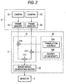
- FIG.2 is a configurative view showing details of the driving assistance system.
- the imaging device 2 includes a camera 21 provided to pick up an image of the left-side area on the back side of the vehicle, a frame memory 22 which temporarily holds image data obtained from the camera 21, a camera 23 provided to pick up an image of the right-side area on the back side of the vehicle, and a frame memory 24 which temporarily holds image data obtained from the camera 23.
- the left side and right side on the back side of the vehicle are picked up by the cameras 21, 23 respectively and then left and right picked-up images are synthesized. But, the left side and right side on the back side of the vehicle might be picked up by one camera at a time.
- the image synthesizing translating system 3 is configured to have an image synthesizing means 31 which synthesizes left-side and right-side images on the back side of the vehicle read from two frame memories 22, 24 of the imaging device 2, a mapping table looking-up means 32 which stores mapping information of respective pixels of the image that is synthesized by the image synthesizing means 31, and an image signal generating means 33 which translates the image synthesized by the image synthesizing means 31 into an image signal.
- the mapping table looking-up means 32 includes a translation address memory 32a which stores translation addresses (a mapping table) indicating correspondences between positional coordinates of respective pixels of an output image (an image displayed on the monitor 4) and positional coordinates of respective pixels of input images (images picked up by the cameras 21, 23), and a degree-of-necessity memory 32b which stores degrees-of-necessity of respective pixels of the input images.
- a translation address memory 32a which stores translation addresses (a mapping table) indicating correspondences between positional coordinates of respective pixels of an output image (an image displayed on the monitor 4) and positional coordinates of respective pixels of input images (images picked up by the cameras 21, 23)
- a degree-of-necessity memory 32b which stores degrees-of-necessity of respective pixels of the input images.
- a “degree-of-necessity” is a value to calculate of addition when a sheet of output image is generated by connecting left-side and right-side input images, for example, such that a degree-of-necessity of the right-side input image is "0.5", a degree-of-necessity of the left-side input image is "0.5", etc. when values of respective pixel data of the area where the left-side and right-side input images combines each other are to be decided.
- the above translation addresses are previously generated on the basis of the three-dimensional projection model described later in detail, and stored in the translation address memory 32a.
- the image synthesizing means 31 generates data of the output pixels by synthesizing respective pixel data in the frame memories 22, 24 by mixers 31a, 31b according to the designated degree-of-necessity based on the translation addresses (the mapping table) recorded in the mapping table looking-up means 32, and then adding the synthesized left-side and right-side pixel data by an adder 31c.
- the image synthesizing means 31 operates based on an appropriate synchronizing signal such as the input image signal, or the like, for example, generates the output image by synthesizing the images input from two different cameras 21, 23 in accordance with the mapping table looking-up means 32 or changing respective pixel positions, and thus connects the input images input from plural different cameras 21, 23 in real time or translates the input images into an image viewed from the virtual viewpoint.
- an appropriate synchronizing signal such as the input image signal, or the like
- the image signal generating means 33 translates output pixel data output from the image synthesizing means 31 to the image signal, and outputs the signal to the monitor 4.
- the translation addresses stored in the mapping table looking-up means 32 are generated based on the three-dimensional projection model according to the present embodiment.
- This three-dimensional projection model is a model indicating correspondences when the images picked up by the cameras 21, 23 are translated to the image that looks as if such image is picked up by the virtual camera which is installed at a virtual viewing position.
- the cameras 21, 23 are wide-angle camera.
- the image on the rear side of the vehicle which can be obtained by synthesizing the picked-up images laterally, is displayed as larger as the image is closer to the vehicle and is displayed as smaller as the image is further from the vehicle, as shown in FIG.3.
- the illustrated example shows the image of a parking area (normally a rectangular area whose vertical dimension is almost 5 m and whose lateral dimension is almost 3 m is shown. This parking area is indicated by a lattice pattern to be easy to understand.) of the rear of the vehicle, which is picked up by the wide-angle camera.
- the image in FIG.3 is displayed on the monitor 4 as the clear and less-distorted image by the translation addresses generated by using the three-dimensional projection model described later.
- FIG.7 is a view showing a three-dimensional projection model used in the present embodiment.
- a three-dimensional projection model 300 used in the present embodiment is configured to include a cylindrical surface model 301 on which the far image is projected, and a spherical surface model 302 which is connected smoothly to the cylindrical surface model 301 and on which the near image is projected.
- An alignment direction of this three-dimensional projection model 300 is different from the conventional three-dimensional projection model 200 explained in FIG.13. That is, the present embodiment is characterized in that an axis of the cylindrical surface model 301 is arranged in parallel with the ground (road surface), i.e., the traveling direction of own vehicle 1, and a lower convex surface of the cylindrical surface model 301 is arranged on the ground side.
- the imaging device 2 installed in the own vehicle 1 to pick up the backward image picks up the backward image in the axial direction of the three-dimensional projection model 300.
- the image synthesizing translating system 3 translates the picked-up image picked up by the imaging device 2 into the image that looks as if such image is picked up by a virtual camera 2a, which is installed over the actual imaging device 2, through the three-dimensional projection model 300, and then displays the image on the monitor 4.
- the cylindrical surface model 301 of the three-dimensional projection model 300 is a semi-spherical model that is installed on the road surface such that a center axis of the cylindrical surface model 301 is in parallel with the traveling direction of the vehicle and is cut in half by a flat surface that passes through the center axis of the cylindrical surface model 301 in parallel with the road surface.
- the spherical surface model 302 is a spherical surface whose radius is identical to a radius of the cylindrical surface model 301, whose center is on the center axis of the cylindrical surface model 301, and whose cut end formed by cutting the sphere by a plane, which passes through the center and has the center axis of the cylindrical surface model 301 as a perpendicular, perfectly coincides with the cylindrical surface model 301. That is, the cylindrical surface model 301 and the spherical surface model 302 can be differentiated at all points (except end points) on the boundary.
- the above three-dimensional projection model 300 is explained as a "circular cylinder” and a "sphere”.
- the model is not always be a perfect "circular cylinder” and a perfect “sphere”, and may be as an ellipse, an elliptic sphere respectively.
- the ellipse that is oblate on the road surface side may be selected as the three-dimensional projection model.
- a view showing by the three-dimensional projection model consisting of this ellipse, which is cut by a flat plane perpendicular to the traveling direction of the vehicle 1, is FIG. 8.
- FIG.8 shows not only the lower half of the ellipse constituting the model but also an overall ellipse.
- FIG. 8 Three three-dimensional projection models are shown in FIG. 8.
- One model is a flat surface model 506 whose direction coincides with the road surface, and the other two models are elliptic models 521, 522 whose ellipticity is respectively different (the portion corresponding to the three-dimensional projection model 301 in FIG.7). Only a length of a minor axis is different between the elliptic models 521, 522.
- FIGs. 9A-9C Views obtained by picking up an image of a lattice pattern, which is depicted on the road surface at an equal interval, by the imaging device 2 shown in FIG.7, and then translating the image into an image that looks as if such image is picked up by the virtual camera 2a shown in FIG.7 through three models 506, 521, 522 shown in FIG.8 are FIGs. 9A-9C respectively. In this case, these images are picked up when the virtual camera 2a is directed just downwards.
- an axis that is in parallel with the center axes of the cylindrical surfaces of the ellipses 521, 522 and is positioned on the road surface is set as a Y axis
- an axis that intersects orthogonally with the Y axis and is perpendicular to the road surface is set as a Z axis
- an axis that intersects orthogonally with the Y axis and the Z axis is set as an X axis
- their values on the Y axis are the same in respective models 506, 521, 522, but their heights become different (values on the Z-axis direction) as the position becomes more distant from the Y axis in the X-axis direction.
- the lines that are in parallel with the Y axis are also depicted as parallel lines on the screens that are translated with using respective models 506, 521, 522.
- the model 522 having a small ellipticity i.e., in which a position goes away from the road surface as the position becomes more distant in the X-axis direction, an interval x2 of the lattice pattern on the end side of the screen becomes narrower than an interval x1 of the lattice pattern around the center, as shown in FIG.9C.
- the cylindrical surface model 521 of the ellipse shown in FIG.8 is used as the cylindrical surface model 301 of the actually used model 300, and the spherical surface model of the ellipse being continued smoothly to the cylindrical surface model 521 of the ellipse is used as the spherical surface model 302) used in the present embodiment, it is decided as follows to what extent the ellipticity of the ellipse that is used as the cylindrical surface model 521 should be set.
- the X axis shown in FIG.8 corresponds to the width direction of own vehicle 1 shown in FIG.7. Therefore, any range 503 is taken out from a range of 80 % to 120 of 3 m which is a width of a normal box of a parking lot having the Y axis as its center. Then, the three-dimensional projection model 521 of the ellipse is set such that a ratio of a maximum value Xmax and a minimum value Xmin of the interval of the lattice pattern, which is formed at an equal interval on the road surface, is at least 80 % or more, as shown in FIG.9B, within the image that is subjected to the translation through the three-dimensional projection model 521 contained in this range 503.
- Such three-dimensional projection model 521 can be easily set by adjusting lengths of a major axis and a minor axis of the ellipse.
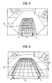
- Views obtained by deciding the cylindrical surface model 301 in FIG.7 based on the ellipse in this manner and displaying the translated image of the lattice pattern are FIG.5 and FIG.6.
- the straight line extending in the same direction as the traveling direction of own vehicle 1 is also displayed as the straight line in the translated image, and the image distortion in the translated image along the width direction can be suppressed into the gentle distortion to such an extent that the driver does not feel a sense of incompatibility.
- the straight lines such as the side line of the road, the side line of the box of the parking lot, etc., which are in parallel with the Y axis, are often used as a mark
- the straight line along the Y axis can also be displayed as the straight line in the translated image.
- the cylindrical surface model 301 is employed as the model on which the picked-up image of the road surface is projected, the straight line is translated into the straight line. As a result, the present embodiment can enjoy this advantage.
- the projecting surface should be set as a surface that gets up from the road surface.
- this projecting surface is set to a surface that suddenly gets up from the cylindrical surface model 301, the image distortion is concentrated onto the boundary portion. Therefore, it is preferable that the projecting surface getting up gradually should be selected. Since the elliptic model 521 gradually gets up in the range 504, the image distortion can be dispersed over the entire screen by using this elliptic model 521 in the range 504. Therefore, it is feasible to provide the translated image that causes the driver to feel less a sense of incompatibility.
- the Y-axis direction corresponds to the traveling direction of the vehicle, i.e., the longitudinal direction of the vehicle
- the image translation is executed in a predetermined range from the rear end of the vehicle by using the model 521 whereas the image translation is executed in a range, which extends beyond the predetermined range from the rear end of the vehicle, by using the elliptic sphere (the model 302 in FIG.7) continued from the model 521.
- this predetermined range in the Y-axis direction should be set any value in 80 % to 120 % of a 5 m range. Also, it is preferable that no inclination is provided to the Y-axis direction in this predetermined range.
- a height of the lowermost position from the road surface is set to zero (coincides with the road surface) over the length of the cylindrical surface model 301. Accordingly, the straight line in the picked-up image in the predetermined range is also displayed as the straight line in the translated image.
- the straight line is displayed as the straight line on this side of a distance-indicating guide line 10 indicating the 2 m range from the rear portion of the vehicle, while the image translation is carried out by using the elliptic sphere model 302 in the range extending beyond 2m.
- the predetermined range is different according to the installation position of the imaging device 2, the resolution, the position of the virtual viewpoint, etc. In this case, it is desired from a point of view of the driving assistance that the ellipse model 301 should be applied in the box of the parking lot range from the rear end of the vehicle 1, which is selected as the predetermined range, and also the elliptic sphere model 302 should be applied in the farther range.
- the three-dimensional projection model is configured with the cylindrical surface model 301 as the ellipse and the spherical surface model 302 as the ellipse. Accordingly, the cylindrical surface model 301 as the ellipse and the spherical surface model 302 as the ellipse are continuously coupled. As a result, as shown in FIG.5 and FIG.6, the translated image is smoothly connected in the boundary surface between the model 301 and the model 302 of the three-dimensional projection model 300. Thus, the driver cannot discriminate the boundary and never perceive a sense of incompatibility.
- an extent of image distortion of the solid body in the range 504 can be adjusted by adjusting the inclination of the projection model in this range 504 shown in FIG.8.
- a distortion level of the image picked up by the imaging device using a wide-angle lens can be adjusted, so that a scale factor of other vehicle in a distant place can be set to get the sense of distance obtained when the driver actually looks out of the rear window.
- FIG.4 illustrated by way of comparison shows the image of a wide-angle lens in FIG.3 from which a lens distortion of the wide-angle lens is eliminated. It is appreciated that, even though only the lens distortion is eliminated, an effect of emphasizing the sense of distance by using the wide-angle lens is not relaxed. That is, a distant image looks more distant, the sense of distance is still emphasized in the image. In contrast, in the present embodiment, since the far image is translated by using the elliptic sphere model 302, the sense of distance is relaxed to provide a clear image, as shown in FIG.5.
- the image shown in FIG.5 can be translated into the image shown in FIG.6 and then displayed on the monitor 4. That is, a width d of the own vehicle 1 on the road surface can be displayed on the screen in an enlarged fashion.
- the image shown in FIG.5 is translated and displayed such that both end positions of the vehicle enter into a 15 % range of the screen width from both end positions of the screen.
- the image near the rear end of the own vehicle 1, which is a blind spot of the driver, is displayed fully on the screen of the monitor 4. Therefore, it gives the driver a sense of security. As a result, the driver can perform the driving operations with a sense of security.
- a bumper image 1a of the own vehicle 1 can be displayed as the straight line, as shown in FIG.5 and FIG.6. Compared with that the bumper image 1a is displayed in curve, as shown in FIG.3 or FIG.4, the driver feels a sense of less-incompatibility to do the driving operations easily.
- a mark 11 indicating a width of the vehicle and a guide line 12 corresponding to a straight line on the road surface, which indicates a side that is in parallel with the traveling direction of the vehicle and is positioned slightly outer than the width d of the vehicle, are displayed. According to these displays, the driver can intuitively grasp the mutual positional relationship between the side line of the road or the box of the parking lot and the driver's own vehicle from the screen to assist the exact driving operation.
- the above three-dimensional projection model configured with the cylindrical surface model and the spherical surface model is not always configured by the curved surfaces that are defined by the equations, and decided based on the application range and the property.
- the cylindrical surface model 301 as the ellipse is not always shaped into the elliptic shape in compliance with the elliptic equation.
- the three-dimensional projection model that is convex downwards and is shaped to disperse the distortion of the translated image over the entire image may be employed. The same is applied to the spherical surface model 302.
- the driving assistance system that is capable of monitoring/displaying the surrounding image of the vehicle as the less-distorted image.
Landscapes
- Engineering & Computer Science (AREA)
- Multimedia (AREA)
- Mechanical Engineering (AREA)
- Physics & Mathematics (AREA)
- General Physics & Mathematics (AREA)
- Theoretical Computer Science (AREA)
- Computer Graphics (AREA)
- Closed-Circuit Television Systems (AREA)
- Image Processing (AREA)
- Image Analysis (AREA)
Applications Claiming Priority (3)
| Application Number | Priority Date | Filing Date | Title |
|---|---|---|---|
| JP2002171484 | 2002-06-12 | ||
| JP2002171484A JP3871614B2 (ja) | 2002-06-12 | 2002-06-12 | 運転支援装置 |
| PCT/JP2003/006482 WO2003107273A1 (ja) | 2002-06-12 | 2003-05-23 | 運転支援装置 |
Publications (2)
| Publication Number | Publication Date |
|---|---|
| EP1513101A1 true EP1513101A1 (de) | 2005-03-09 |
| EP1513101A4 EP1513101A4 (de) | 2010-10-06 |
Family
ID=29727811
Family Applications (1)
| Application Number | Title | Priority Date | Filing Date |
|---|---|---|---|
| EP20030730616 Withdrawn EP1513101A4 (de) | 2002-06-12 | 2003-05-23 | Fahrhilfesystem |
Country Status (5)
| Country | Link |
|---|---|
| US (1) | US7554573B2 (de) |
| EP (1) | EP1513101A4 (de) |
| JP (1) | JP3871614B2 (de) |
| KR (1) | KR100937750B1 (de) |
| WO (1) | WO2003107273A1 (de) |
Cited By (2)
| Publication number | Priority date | Publication date | Assignee | Title |
|---|---|---|---|---|
| DE102007049821A1 (de) * | 2007-10-16 | 2009-04-23 | Daimler Ag | Verfahren zum Kalibrieren einer Anordnung mit mindestens einer omnidirektionalen Kamera und einer optischen Anzeigeeinheit |
| EP2860063A1 (de) * | 2013-10-08 | 2015-04-15 | Hyundai Motor Company | Verfahren und Vorrichtung zur Erfassung eines Bildes für Fahrzeug |
Families Citing this family (65)
| Publication number | Priority date | Publication date | Assignee | Title |
|---|---|---|---|---|
| WO2005088970A1 (ja) * | 2004-03-11 | 2005-09-22 | Olympus Corporation | 画像生成装置、画像生成方法、および画像生成プログラム |
| US7782374B2 (en) * | 2005-03-03 | 2010-08-24 | Nissan Motor Co., Ltd. | Processor and processing method for generating a panoramic image for a vehicle |
| JP4596978B2 (ja) * | 2005-03-09 | 2010-12-15 | 三洋電機株式会社 | 運転支援システム |
| JP4715334B2 (ja) * | 2005-06-24 | 2011-07-06 | 日産自動車株式会社 | 車両用画像生成装置および方法 |
| JP4727329B2 (ja) * | 2005-07-15 | 2011-07-20 | パナソニック株式会社 | 画像合成装置及び画像合成方法 |
| JP4677847B2 (ja) * | 2005-08-01 | 2011-04-27 | 日産自動車株式会社 | 車両用周囲監視装置及び車両周囲監視方法 |
| WO2007015446A1 (ja) * | 2005-08-02 | 2007-02-08 | Nissan Motor Co., Ltd. | 車両周囲監視装置及び車両周囲監視方法 |
| JP4679293B2 (ja) * | 2005-08-08 | 2011-04-27 | 三洋電機株式会社 | 車載パノラマカメラシステム |
| JP4810953B2 (ja) * | 2005-10-07 | 2011-11-09 | 日産自動車株式会社 | 車両用死角映像表示装置 |
| JP2007180803A (ja) | 2005-12-27 | 2007-07-12 | Aisin Aw Co Ltd | 運転支援方法及び運転支援装置 |
| US20090128630A1 (en) * | 2006-07-06 | 2009-05-21 | Nissan Motor Co., Ltd. | Vehicle image display system and image display method |
| JP5159070B2 (ja) * | 2006-08-31 | 2013-03-06 | アルパイン株式会社 | 車両周辺画像表示装置及び表示方法 |
| JP4927512B2 (ja) * | 2006-12-05 | 2012-05-09 | 株式会社日立製作所 | 画像生成装置 |
| JP4853712B2 (ja) * | 2006-12-28 | 2012-01-11 | アイシン精機株式会社 | 駐車支援装置 |
| JP4924896B2 (ja) * | 2007-07-05 | 2012-04-25 | アイシン精機株式会社 | 車両の周辺監視装置 |
| JP2009053818A (ja) * | 2007-08-24 | 2009-03-12 | Toshiba Corp | 画像処理装置及びその方法 |
| JP2009060404A (ja) * | 2007-08-31 | 2009-03-19 | Denso Corp | 映像処理装置 |
| TW200925023A (en) * | 2007-12-07 | 2009-06-16 | Altek Corp | Method of displaying shot image on car reverse video system |
| JP4934579B2 (ja) * | 2007-12-14 | 2012-05-16 | 三洋電機株式会社 | 運転支援装置 |
| US8884883B2 (en) * | 2008-01-25 | 2014-11-11 | Microsoft Corporation | Projection of graphical objects on interactive irregular displays |
| US9218116B2 (en) * | 2008-07-25 | 2015-12-22 | Hrvoje Benko | Touch interaction with a curved display |
| US8704907B2 (en) * | 2008-10-30 | 2014-04-22 | Panasonic Corporation | Camera body and camera system with interchangeable lens for performing image data correction |
| US8446367B2 (en) * | 2009-04-17 | 2013-05-21 | Microsoft Corporation | Camera-based multi-touch mouse |
| JP5376223B2 (ja) * | 2009-05-18 | 2013-12-25 | アイシン精機株式会社 | 運転支援装置 |
| JP5135380B2 (ja) * | 2010-04-12 | 2013-02-06 | 住友重機械工業株式会社 | 処理対象画像生成装置、処理対象画像生成方法、及び操作支援システム |
| JP5550970B2 (ja) * | 2010-04-12 | 2014-07-16 | 住友重機械工業株式会社 | 画像生成装置及び操作支援システム |
| DE102010015079A1 (de) | 2010-04-15 | 2011-10-20 | Valeo Schalter Und Sensoren Gmbh | Verfahren zum Anzeigen eines Bildes auf einer Anzeigeeinrichtung in einem Fahrzeug. Fahrerassistenzsystem und Fahrzeug |
| JP5387763B2 (ja) | 2010-05-25 | 2014-01-15 | 富士通株式会社 | 映像処理装置、映像処理方法及び映像処理プログラム |
| KR101448411B1 (ko) | 2010-08-19 | 2014-10-07 | 닛산 지도우샤 가부시키가이샤 | 입체물 검출 장치 및 입체물 검출 방법 |
| JP5555101B2 (ja) * | 2010-08-31 | 2014-07-23 | 株式会社日立情報通信エンジニアリング | 画像補正装置、補正画像生成方法および補正画像生成プログラム |
| JP5558973B2 (ja) | 2010-08-31 | 2014-07-23 | 株式会社日立情報通信エンジニアリング | 画像補正装置、補正画像生成方法、補正テーブル生成装置、補正テーブル生成方法、補正テーブル生成プログラムおよび補正画像生成プログラム |
| DE102010042276A1 (de) | 2010-10-11 | 2012-04-12 | Robert Bosch Gmbh | Sensor, Justageverfahren und Vermessungsverfahren für einen Sensor |
| DE102010042248A1 (de) * | 2010-10-11 | 2012-04-12 | Robert Bosch Gmbh | Verfahren und Vorrichtung zur optischen Darstellung einer Umgebung eines Fahrzeugs |
| JP5544277B2 (ja) * | 2010-10-29 | 2014-07-09 | 株式会社日立情報通信エンジニアリング | 画像補正装置、補正画像生成方法、補正テーブル生成装置、補正テーブル生成方法、補正テーブル生成プログラムおよび補正画像生成プログラム |
| WO2012089258A1 (en) * | 2010-12-29 | 2012-07-05 | Tele Atlas Polska Sp.Z.O.O | Methods for mapping and associated apparatus |
| DE102011010860A1 (de) * | 2011-02-10 | 2012-08-16 | Connaught Electronics Ltd. | Verfahren und Fahrerassistenzsystem zum Anzeigen von Bildern in einem Kraftfahrzeug sowie Kraftfahrzeug |
| JP5124671B2 (ja) * | 2011-06-07 | 2013-01-23 | 株式会社小松製作所 | 作業車両の周辺監視装置 |
| JP5124672B2 (ja) | 2011-06-07 | 2013-01-23 | 株式会社小松製作所 | 作業車両の周辺監視装置 |
| JP6739897B2 (ja) * | 2011-07-18 | 2020-08-12 | カデンス メディカル イメージング インコーポレイテッド | レンダリングを行う方法及びシステム |
| EP2554434B1 (de) * | 2011-08-05 | 2014-05-21 | Harman Becker Automotive Systems GmbH | Fahrzeug-Surround-Blicksystem |
| GB2494414A (en) | 2011-09-06 | 2013-03-13 | Land Rover Uk Ltd | Terrain visualisation for vehicle using combined colour camera and time of flight (ToF) camera images for augmented display |
| BR112014002366B1 (pt) * | 2011-09-12 | 2021-10-05 | Nissan Motor Co., Ltd | Dispositivo e método de detecção de objeto tridimensional |
| JP5682788B2 (ja) * | 2011-09-27 | 2015-03-11 | アイシン精機株式会社 | 車両周辺監視装置 |
| KR101265711B1 (ko) * | 2011-11-30 | 2013-05-20 | 주식회사 이미지넥스트 | 3d 차량 주변 영상 생성 방법 및 장치 |
| JP5861871B2 (ja) * | 2011-12-28 | 2016-02-16 | スズキ株式会社 | 俯瞰画像提示装置 |
| DE102012203171A1 (de) * | 2012-02-29 | 2013-08-29 | Bayerische Motoren Werke Aktiengesellschaft | Verfahren und Vorrichtung zur Bildverarbeitung von Bilddaten |
| US10046700B2 (en) | 2012-05-22 | 2018-08-14 | Mitsubishi Electric Corporation | Image processing device |
| US9225942B2 (en) * | 2012-10-11 | 2015-12-29 | GM Global Technology Operations LLC | Imaging surface modeling for camera modeling and virtual view synthesis |
| WO2014073282A1 (ja) * | 2012-11-08 | 2014-05-15 | 住友重機械工業株式会社 | 舗装機械用画像生成装置及び舗装機械用操作支援システム |
| US20150077560A1 (en) * | 2013-03-22 | 2015-03-19 | GM Global Technology Operations LLC | Front curb viewing system based upon dual cameras |
| JP6302624B2 (ja) * | 2013-04-24 | 2018-03-28 | 住友重機械工業株式会社 | 画像生成装置 |
| WO2015104860A1 (ja) * | 2014-01-10 | 2015-07-16 | アイシン精機株式会社 | 画像表示制御装置および画像表示システム |
| DE102014116441A1 (de) * | 2014-11-11 | 2016-05-12 | Connaught Electronics Ltd. | Verfahren zum Darstellen einer Sicherheitsinformation, Fahrerassistenzsystem und Kraftfahrzeug |
| JP6293089B2 (ja) * | 2015-05-12 | 2018-03-14 | 萩原電気株式会社 | 後方モニタ |
| US10412359B2 (en) * | 2015-06-11 | 2019-09-10 | Conti Temic Microelectronic Gmbh | Method for generating a virtual image of vehicle surroundings |
| DE102016211227A1 (de) * | 2016-06-23 | 2017-12-28 | Conti Temic Microelectronic Gmbh | Verfahren und Fahrzeugsteuersystem zum Erzeugen von Abbildungen eines Umfeldmodells und entsprechendes Fahrzeug |
| DE102016217488A1 (de) * | 2016-09-14 | 2018-03-15 | Robert Bosch Gmbh | Verfahren zum Bereitstellen einer Rückspiegelansicht einer Fahrzeugumgebung eines Fahrzeugs |
| DE102016225066A1 (de) | 2016-12-15 | 2018-06-21 | Conti Temic Microelectronic Gmbh | Rundumsichtsystem für ein Fahrzeug |
| US10268907B2 (en) * | 2017-01-11 | 2019-04-23 | GM Global Technology Operations LLC | Methods and systems for providing notifications on camera displays for vehicles |
| JP6958163B2 (ja) * | 2017-09-20 | 2021-11-02 | 株式会社アイシン | 表示制御装置 |
| JP6975003B2 (ja) * | 2017-09-29 | 2021-12-01 | 株式会社デンソー | 周辺監視装置およびその校正方法 |
| CN110045721B (zh) * | 2018-01-17 | 2022-10-28 | 大陆泰密克汽车系统(上海)有限公司 | 用于辅助车辆行驶的方法及其装置 |
| TWI688502B (zh) * | 2018-02-14 | 2020-03-21 | 先進光電科技股份有限公司 | 用於警告車輛障礙物的設備 |
| DE102018203590A1 (de) | 2018-03-09 | 2019-09-12 | Conti Temic Microelectronic Gmbh | Surroundview-System mit angepasster Projektionsfläche |
| JP7208356B2 (ja) * | 2018-09-26 | 2023-01-18 | コーヒレント・ロジックス・インコーポレーテッド | 任意の世界ビューの生成 |
Citations (3)
| Publication number | Priority date | Publication date | Assignee | Title |
|---|---|---|---|---|
| GB2361376A (en) * | 1999-09-30 | 2001-10-17 | Toyoda Automatic Loom Works | Image conversion device for vehicle rearward-monitoring device |
| EP1170173A2 (de) * | 2000-07-07 | 2002-01-09 | Matsushita Electric Industrial Co., Ltd. | Bildzusammensetzungssystem und -verfahren |
| JP2002127852A (ja) * | 2000-10-27 | 2002-05-09 | Aisin Seiki Co Ltd | 車両周辺表示装置 |
Family Cites Families (14)
| Publication number | Priority date | Publication date | Assignee | Title |
|---|---|---|---|---|
| JPH039952A (ja) * | 1989-06-08 | 1991-01-17 | Nippon Steel Chem Co Ltd | 熱可塑性樹脂組成物 |
| JPH0399952A (ja) * | 1989-09-12 | 1991-04-25 | Nissan Motor Co Ltd | 車両用周囲状況モニタ |
| US5670935A (en) * | 1993-02-26 | 1997-09-23 | Donnelly Corporation | Rearview vision system for vehicle including panoramic view |
| US6498620B2 (en) * | 1993-02-26 | 2002-12-24 | Donnelly Corporation | Vision system for a vehicle including an image capture device and a display system having a long focal length |
| US6550949B1 (en) * | 1996-06-13 | 2003-04-22 | Gentex Corporation | Systems and components for enhancing rear vision from a vehicle |
| KR20010112433A (ko) * | 1999-04-16 | 2001-12-20 | 마츠시타 덴끼 산교 가부시키가이샤 | 화상처리장치 및 감시시스템 |
| JP4312883B2 (ja) * | 1999-06-29 | 2009-08-12 | 富士通テン株式会社 | 車両の駐車支援装置 |
| JP3301421B2 (ja) | 1999-10-20 | 2002-07-15 | 松下電器産業株式会社 | 車両周囲状況提示装置 |
| JP2001339716A (ja) * | 2000-05-25 | 2001-12-07 | Matsushita Electric Ind Co Ltd | 車両周辺監視装置及び方法 |
| JP4433575B2 (ja) * | 2000-06-16 | 2010-03-17 | 株式会社豊田中央研究所 | 車載撮像装置 |
| JP3372944B2 (ja) * | 2000-07-19 | 2003-02-04 | 松下電器産業株式会社 | 監視システム |
| JP4629839B2 (ja) * | 2000-09-07 | 2011-02-09 | クラリオン株式会社 | 画像変換装置 |
| JP3906896B2 (ja) * | 2000-11-28 | 2007-04-18 | 三菱自動車工業株式会社 | 駐車支援装置 |
| JP2003054340A (ja) * | 2001-08-08 | 2003-02-26 | Yazaki Corp | 駐車支援装置 |
-
2002
- 2002-06-12 JP JP2002171484A patent/JP3871614B2/ja not_active Expired - Lifetime
-
2003
- 2003-05-23 WO PCT/JP2003/006482 patent/WO2003107273A1/ja active Application Filing
- 2003-05-23 KR KR1020047005845A patent/KR100937750B1/ko active IP Right Grant
- 2003-05-23 EP EP20030730616 patent/EP1513101A4/de not_active Withdrawn
- 2003-05-23 US US10/488,458 patent/US7554573B2/en not_active Expired - Lifetime
Patent Citations (3)
| Publication number | Priority date | Publication date | Assignee | Title |
|---|---|---|---|---|
| GB2361376A (en) * | 1999-09-30 | 2001-10-17 | Toyoda Automatic Loom Works | Image conversion device for vehicle rearward-monitoring device |
| EP1170173A2 (de) * | 2000-07-07 | 2002-01-09 | Matsushita Electric Industrial Co., Ltd. | Bildzusammensetzungssystem und -verfahren |
| JP2002127852A (ja) * | 2000-10-27 | 2002-05-09 | Aisin Seiki Co Ltd | 車両周辺表示装置 |
Non-Patent Citations (1)
| Title |
|---|
| See also references of WO03107273A1 * |
Cited By (3)
| Publication number | Priority date | Publication date | Assignee | Title |
|---|---|---|---|---|
| DE102007049821A1 (de) * | 2007-10-16 | 2009-04-23 | Daimler Ag | Verfahren zum Kalibrieren einer Anordnung mit mindestens einer omnidirektionalen Kamera und einer optischen Anzeigeeinheit |
| US8599258B2 (en) | 2007-10-16 | 2013-12-03 | Daimler Ag | Method for calibrating an assembly using at least one omnidirectional camera and an optical display unit |
| EP2860063A1 (de) * | 2013-10-08 | 2015-04-15 | Hyundai Motor Company | Verfahren und Vorrichtung zur Erfassung eines Bildes für Fahrzeug |
Also Published As
| Publication number | Publication date |
|---|---|
| JP3871614B2 (ja) | 2007-01-24 |
| US7554573B2 (en) | 2009-06-30 |
| KR20040111329A (ko) | 2004-12-31 |
| KR100937750B1 (ko) | 2010-01-20 |
| US20040260469A1 (en) | 2004-12-23 |
| WO2003107273A1 (ja) | 2003-12-24 |
| EP1513101A4 (de) | 2010-10-06 |
| JP2004021307A (ja) | 2004-01-22 |
Similar Documents
| Publication | Publication Date | Title |
|---|---|---|
| US7554573B2 (en) | Drive assisting system | |
| EP1701306B1 (de) | Fahrhilfssystem | |
| JP3286306B2 (ja) | 画像生成装置、画像生成方法 | |
| JP6310652B2 (ja) | 映像表示システム、映像合成装置及び映像合成方法 | |
| JP3300334B2 (ja) | 画像処理装置および監視システム | |
| JP5077307B2 (ja) | 車両周囲画像表示制御装置 | |
| EP1383332A1 (de) | Verfahren und vorrichtung zum anzeigen eines abnahmebildes einer in einem fahrzeug installierten kamera | |
| JP4248570B2 (ja) | 画像処理装置並びに視界支援装置及び方法 | |
| US20090179916A1 (en) | Method and apparatus for calibrating a video display overlay | |
| JP2008077628A (ja) | 画像処理装置並びに車両周辺視界支援装置及び方法 | |
| DE102013220669A1 (de) | Dynamische Rückspiegelanzeigemerkmale | |
| US20190100145A1 (en) | Three-dimensional image driving assistance device | |
| US10453173B2 (en) | Panel transform | |
| EP3326146B1 (de) | Schneller rückblick auf querverkehr | |
| JP5305750B2 (ja) | 車両周辺表示装置およびその表示方法 | |
| JP4706896B2 (ja) | 広角画像の補正方法及び車両の周辺監視システム | |
| US20220222947A1 (en) | Method for generating an image of vehicle surroundings, and apparatus for generating an image of vehicle surroundings | |
| CN218877068U (zh) | 具有图像合成功能的数字式后视镜、车机系统和车辆 | |
| JP6007773B2 (ja) | 画像データ変換装置並びにナビゲーションシステムおよびカメラ装置並びに車両 | |
| CN117011185B (zh) | 一种电子后视镜cms图像矫正方法、系统及电子后视镜 | |
| JP6657937B2 (ja) | 車両用表示装置 | |
| JP2004007299A (ja) | 車両用映像表示装置 | |
| JPWO2020233755A5 (de) |
Legal Events
| Date | Code | Title | Description |
|---|---|---|---|
| PUAI | Public reference made under article 153(3) epc to a published international application that has entered the european phase |
Free format text: ORIGINAL CODE: 0009012 |
|
| 17P | Request for examination filed |
Effective date: 20040305 |
|
| AK | Designated contracting states |
Kind code of ref document: A1 Designated state(s): AT BE BG CH CY CZ DE DK EE ES FI FR GB GR HU IE IT LI LU MC NL PT RO SE SI SK TR |
|
| AX | Request for extension of the european patent |
Extension state: AL LT LV MK |
|
| DAX | Request for extension of the european patent (deleted) | ||
| RBV | Designated contracting states (corrected) |
Designated state(s): DE FR GB IT SE |
|
| RAP1 | Party data changed (applicant data changed or rights of an application transferred) |
Owner name: PANASONIC CORPORATION |
|
| A4 | Supplementary search report drawn up and despatched |
Effective date: 20100902 |
|
| RAP1 | Party data changed (applicant data changed or rights of an application transferred) |
Owner name: PANASONIC INTELLECTUAL PROPERTY MANAGEMENT CO., LT |
|
| RAP1 | Party data changed (applicant data changed or rights of an application transferred) |
Owner name: PANASONIC INTELLECTUAL PROPERTY MANAGEMENT CO., LT |
|
| 17Q | First examination report despatched |
Effective date: 20150309 |
|
| STAA | Information on the status of an ep patent application or granted ep patent |
Free format text: STATUS: EXAMINATION IS IN PROGRESS |
|
| STAA | Information on the status of an ep patent application or granted ep patent |
Free format text: STATUS: THE APPLICATION IS DEEMED TO BE WITHDRAWN |
|
| 18D | Application deemed to be withdrawn |
Effective date: 20180619 |
|
| RIC1 | Information provided on ipc code assigned before grant |
Ipc: B60R 1/00 20060101ALI20040108BHEP Ipc: G06T 3/00 20060101AFI20040108BHEP Ipc: B60R 21/00 20060101ALI20040108BHEP Ipc: G06T 1/00 20060101ALI20040108BHEP Ipc: H04N 7/18 20060101ALI20040108BHEP |