EP1512554B1 - Luftreifen - Google Patents
Luftreifen Download PDFInfo
- Publication number
- EP1512554B1 EP1512554B1 EP04016028A EP04016028A EP1512554B1 EP 1512554 B1 EP1512554 B1 EP 1512554B1 EP 04016028 A EP04016028 A EP 04016028A EP 04016028 A EP04016028 A EP 04016028A EP 1512554 B1 EP1512554 B1 EP 1512554B1
- Authority
- EP
- European Patent Office
- Prior art keywords
- tyre
- layer
- tread
- rubber
- base layer
- Prior art date
- Legal status (The legal status is an assumption and is not a legal conclusion. Google has not performed a legal analysis and makes no representation as to the accuracy of the status listed.)
- Expired - Lifetime
Links
- VYPSYNLAJGMNEJ-UHFFFAOYSA-N Silicium dioxide Chemical compound O=[Si]=O VYPSYNLAJGMNEJ-UHFFFAOYSA-N 0.000 claims description 60
- 239000000377 silicon dioxide Substances 0.000 claims description 30
- 230000002093 peripheral effect Effects 0.000 claims description 9
- 229920001971 elastomer Polymers 0.000 description 102
- 239000005060 rubber Substances 0.000 description 102
- 235000019589 hardness Nutrition 0.000 description 41
- 239000000203 mixture Substances 0.000 description 38
- 238000005096 rolling process Methods 0.000 description 22
- 230000000052 comparative effect Effects 0.000 description 16
- 239000006229 carbon black Substances 0.000 description 14
- 238000012360 testing method Methods 0.000 description 14
- OKTJSMMVPCPJKN-UHFFFAOYSA-N Carbon Chemical compound [C] OKTJSMMVPCPJKN-UHFFFAOYSA-N 0.000 description 9
- 229910052799 carbon Inorganic materials 0.000 description 9
- 239000011324 bead Substances 0.000 description 8
- 230000000694 effects Effects 0.000 description 5
- 239000000463 material Substances 0.000 description 5
- 229910052751 metal Inorganic materials 0.000 description 5
- 239000002184 metal Substances 0.000 description 5
- 239000010409 thin film Substances 0.000 description 4
- 239000002202 Polyethylene glycol Substances 0.000 description 3
- 239000002216 antistatic agent Substances 0.000 description 3
- 230000005611 electricity Effects 0.000 description 3
- 150000002148 esters Chemical class 0.000 description 3
- 229920003049 isoprene rubber Polymers 0.000 description 3
- 229920001223 polyethylene glycol Polymers 0.000 description 3
- 239000012744 reinforcing agent Substances 0.000 description 3
- 244000043261 Hevea brasiliensis Species 0.000 description 2
- 239000005062 Polybutadiene Substances 0.000 description 2
- 239000004020 conductor Substances 0.000 description 2
- 239000000314 lubricant Substances 0.000 description 2
- 229920003052 natural elastomer Polymers 0.000 description 2
- 229920001194 natural rubber Polymers 0.000 description 2
- 229920002857 polybutadiene Polymers 0.000 description 2
- 230000003068 static effect Effects 0.000 description 2
- 229920003048 styrene butadiene rubber Polymers 0.000 description 2
- 229910000838 Al alloy Inorganic materials 0.000 description 1
- 229910000831 Steel Inorganic materials 0.000 description 1
- 238000005299 abrasion Methods 0.000 description 1
- 150000001875 compounds Chemical class 0.000 description 1
- 238000004132 cross linking Methods 0.000 description 1
- 239000003431 cross linking reagent Substances 0.000 description 1
- 230000001419 dependent effect Effects 0.000 description 1
- 238000001125 extrusion Methods 0.000 description 1
- 239000000945 filler Substances 0.000 description 1
- 238000007429 general method Methods 0.000 description 1
- 230000020169 heat generation Effects 0.000 description 1
- 238000010438 heat treatment Methods 0.000 description 1
- 238000005259 measurement Methods 0.000 description 1
- 238000000034 method Methods 0.000 description 1
- 238000002156 mixing Methods 0.000 description 1
- 238000000465 moulding Methods 0.000 description 1
- 230000000704 physical effect Effects 0.000 description 1
- 230000003014 reinforcing effect Effects 0.000 description 1
- 230000035939 shock Effects 0.000 description 1
- 239000010959 steel Substances 0.000 description 1
- 238000010998 test method Methods 0.000 description 1
- XLYOFNOQVPJJNP-UHFFFAOYSA-N water Substances O XLYOFNOQVPJJNP-UHFFFAOYSA-N 0.000 description 1
Images
Classifications
-
- B—PERFORMING OPERATIONS; TRANSPORTING
- B60—VEHICLES IN GENERAL
- B60C—VEHICLE TYRES; TYRE INFLATION; TYRE CHANGING; CONNECTING VALVES TO INFLATABLE ELASTIC BODIES IN GENERAL; DEVICES OR ARRANGEMENTS RELATED TO TYRES
- B60C11/00—Tyre tread bands; Tread patterns; Anti-skid inserts
-
- B—PERFORMING OPERATIONS; TRANSPORTING
- B60—VEHICLES IN GENERAL
- B60C—VEHICLE TYRES; TYRE INFLATION; TYRE CHANGING; CONNECTING VALVES TO INFLATABLE ELASTIC BODIES IN GENERAL; DEVICES OR ARRANGEMENTS RELATED TO TYRES
- B60C11/00—Tyre tread bands; Tread patterns; Anti-skid inserts
- B60C11/0041—Tyre tread bands; Tread patterns; Anti-skid inserts comprising different tread rubber layers
- B60C11/005—Tyre tread bands; Tread patterns; Anti-skid inserts comprising different tread rubber layers with cap and base layers
- B60C11/0058—Tyre tread bands; Tread patterns; Anti-skid inserts comprising different tread rubber layers with cap and base layers with different cap rubber layers in the axial direction
-
- B—PERFORMING OPERATIONS; TRANSPORTING
- B60—VEHICLES IN GENERAL
- B60C—VEHICLE TYRES; TYRE INFLATION; TYRE CHANGING; CONNECTING VALVES TO INFLATABLE ELASTIC BODIES IN GENERAL; DEVICES OR ARRANGEMENTS RELATED TO TYRES
- B60C19/00—Tyre parts or constructions not otherwise provided for
- B60C19/08—Electric-charge-dissipating arrangements
-
- Y—GENERAL TAGGING OF NEW TECHNOLOGICAL DEVELOPMENTS; GENERAL TAGGING OF CROSS-SECTIONAL TECHNOLOGIES SPANNING OVER SEVERAL SECTIONS OF THE IPC; TECHNICAL SUBJECTS COVERED BY FORMER USPC CROSS-REFERENCE ART COLLECTIONS [XRACs] AND DIGESTS
- Y10—TECHNICAL SUBJECTS COVERED BY FORMER USPC
- Y10S—TECHNICAL SUBJECTS COVERED BY FORMER USPC CROSS-REFERENCE ART COLLECTIONS [XRACs] AND DIGESTS
- Y10S152/00—Resilient tires and wheels
- Y10S152/02—Static discharge
Definitions
- the present invention relates to a structure of a pneumatic tyre (hereinafter referred to as a "tyre").
- a portion to come in contact with the road surface of a tyre is particularly referred to as a tread.
- the tread has a tread rubber layer.
- the physical properties of a rubber constituting the tread rubber layer directly influence the performance of the tyre.
- importance has been particularly attached to a wet grip performance and a rolling resistance in the performance of the tyre.
- the rolling resistance generally tends to be increased.
- the tyre has conventionally been improved to suppress a rise in the rolling resistance with an enhancement in the wet grip performance.
- silica is blended with the rubber constituting the tread rubber layer in place of carbon black to be a reinforcing agent.
- the tread rubber layer is constituted to have a two-layer structure including outer and inner layers, and the outer layer is constituted by a rubber having an excellent grip performance and the inner layer is constituted by a rubber of a low heat generating type.
- the outer layer is constituted by a rubber having an excellent grip performance
- the inner layer is constituted by a rubber of a low heat generating type.
- the silica In some cases in which the silica is blended with the rubber constituting the tread rubber layer, however, the silica has a poor conductiveness and static electricity is therefore stored in a vehicle to which the tyre is attached.
- polyethylene glycol ester or the like is blended as an antistatic agent with the rubber constituting the tread rubber layer in some cases. Even if such an antistatic agent is used, however, the following trouble is made. More specifically, when the amount of the polyethylene glycol ester to be blended is small, an antistatic effect is reduced. On the other hand, when the amount of the polyethylene glycol ester to be blended is large, there is a problem in that the antistatic effect is obtained but the abrasion resistance performance of a tyre is deteriorated by blending the antistatic agent.
- a conductive layer is formed and a conductive member is provided on an inside in the radial direction of the tread rubber layer.
- the conductive member is connected to the conductive layer and is provided to penetrate through the outer peripheral surface (tread surface) of a tread portion.
- the conductive member is thus disposed, static electricity is grounded through the conductive member. Consequently, the antistatic effect can be obtained.
- the conductive member is provided in the radial direction of the tyre. Therefore, there is a problem in that a two-layer structure to reconcile a high wet grip performance to a low rolling resistance is formed well with difficulty.
- JP 11 115 414 A discloses a tyre in accordance with the preamble of claim 1. Further prior art is known from EP 0 798 142 A1 .
- the present invention has been made in such a background. It is an object of the present invention to provide a tyre which exhibits a high antistatic effect and reduces a rolling resistance. The object is satisfied by the features of claim 1. Further embodiments of the invention are mentioned in the dependent claims.
- the tread has the two-layer structure, and a plurality of circular convex portions is provided on the base layer to be an inner layer and is exposed to the tread surface.
- the rubber constituting the cap layer is not particularly excellent in the conductiveness, therefore, a sufficient conductiveness can be maintained between the tyre and the road surface.
- the silica is blended with the rubber constituting the tread, for example, the tyre can exhibit a high conductiveness and can reduce the rolling resistance.
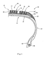
- Fig. 1 shows a section taken along a plane which passes through the center of a tyre 10 and is orthogonal to an equator plane E of the tyre 10.
- a vertical direction is set to be a radial direction of the tyre 10 and a transverse direction is set to be an axial direction of the tyre 10.
- the tyre 10 takes an almost symmetrical shape about the equator plane E, and has a carcass 11, a sidewall 12, a bead 13 and a tread 14 and is provided with a belt 15 for reinforcing the carcass 11.
- the tread 14 includes a tread rubber layer 16 formed of a crosslinked rubber.
- the tread rubber layer 16 is formed to take the shape of an almost circular arc to be outward convex in the radial direction.
- the outer peripheral surface of the tread rubber layer 16 constitutes a tread surface 17 to come in contact with a road surface.
- the tread surface 17 is provided with a groove 18. Consequently, a land portion 19 is formed on the tread 14. By the presence of the groove 18 and the land portion 19, a tread pattern is formed.
- the structure of the tread rubber layer 16 will be described below in detail.
- the sidewall 12 is extended inward in the radial direction from both ends of the tread 14.
- a buttress portion 22 is provided in a boundary part between the sidewall 12 and the tread 14.
- the sidewall 12 is also formed of a crosslinked rubber. By a flexure, the sidewall 12 absorbs a shock generated from the road surface. Moreover, the sidewall 12 prevents the external damage of the carcass 11.
- the bead 13 has a bead core 20.
- the bead core 20 is formed circularly.
- the bead core 20 is formed by a plurality of non-extensible wires (typically, wires formed of steel).
- the carcass 11 includes a carcass ply 21.
- the carcass ply 21 constitutes the frame of the tyre 10.
- the carcass ply 21 is provided along the inner peripheral surfaces of the tread 14, the sidewall 12 and the bead 13 and is laid over the bead core 20.
- the belt 15 is obtained by covering a belt cord with a crosslinked rubber and covers and reinforces the carcass 11.
- the carcass 11, the belt 15, the sidewall 12, the bead 13 and the like are manufactured by a general method which has conventionally been employed, and these are constituted integrally in the tyre 10 which is formed.
- the tread 14 includes the tread rubber layer 16 formed of the crosslinked rubber.
- the buttress portion 22 is formed in the boundary part between the tread rubber layer 16 and the sidewall 12.
- the present embodiment features the structure of the tread rubber layer 16. More specifically, the present embodiment is characterized in that:
- the base layer 23 is formed like a comb protruded outward in the radial direction, and the cap layer 24 is provided to cover the base layer 23 at an outside in the radial direction.
- the base layer 23 and the cap layer 24 are constituted by a rubber (referred to as a "tread rubber"), respectively.
- the base layer 23 and the cap layer 24 are constituted by heating (crosslinking), for a predetermined time, a base material (rubber) to which a crosslinking agent or another compound is added.
- the base material it is possible to employ a natural rubber (NR), a styrene-butadiene rubber (SBR), a butadiene rubber (BR), an isoprene rubber (IR) or their mixtures, and particularly, it is preferable that the styrene-butadiene rubber (SBR) should be employed.
- NR natural rubber
- SBR styrene-butadiene rubber
- BR butadiene rubber
- IR isoprene rubber
- Carbon black, silica or the like may be added as a reinforcing agent to the base material.
- other various fillers may be added to the base material.
- the hardness of the base layer 23 is different from that of the cap layer 24. More specifically, the hardness of the base layer 23 has a JIS A hardness set to be 60 and the hardness of the cap layer 24 has a JIS A hardness set to be 64.
- the hardnesses of the base layer 23 and the cap layer 24 are not restricted to these values. It is preferable that the hardness of the base layer 23 should be set to be smaller than that of the cap layer 24 and both of the hardnesses should have the JIS A hardnesses set to be 55 to 65.
- the silica is blended with the cap layer 24 and is not blended with the base layer 23.
- the groove 18 is provided on the outer peripheral surface of the cap layer 24 (the tread surface 17).
- the groove 18 is formed circularly on the tread surface 17 in the circumferential direction.
- the groove 18 is provided in the central part of the tread surface 17 , and is provided symmetrically in an axial direction about the central part (see Fig. 1 ). Indeed, it is a matter of course that a large number of grooves 18 may be provided asymmetrically based on the equator plane E.
- the groove 18 is formed in such a manner that an internal wall surface thereof takes an almost U shape.
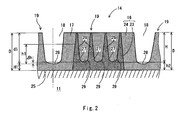
- a thickness D of the tread rubber layer 16 is set to be 10 mm and a depth d1 of the groove 18 is set to be 8.2 mm.
- a subtread gauge H1 is set to be 1.8 mm.
- the subtread gauge H1 represents a distance between an inner bottom portion 28 of the groove 18 and a bottom face 25 of the tread rubber layer 16.
- the base layer 23 is formed like a comb as described above, and includes a plurality of convex portions 26 (circular convex portions) as shown in Fig. 2 . As shown in Fig. 1 , these base layers 23 are arranged in the axial direction of the tyre 10 and the convex portion 26 of each base layer 23 is provided to be buried in the land portion 19. More specifically, as shown in Fig. 2 , the base layer 23 has four convex portions 26. Each of the convex portions 26 is arranged in the radial direction (the transverse direction in Fig. 2 ), and the adjacent convex portions 26 are provided smoothly and continuously by a circular arc portion 27. Although the number of the convex portions 26 is not restricted to four, it is preferable that the number of the convex portions 26 to be provided in one land portion 19 should be two to five.
- a height h1 of the convex portion 26 is properly set to be 15% to 50% of the depth d1 of the groove 18.
- the height h1 of the convex portion 26 represents a distance between the top portion of the convex portion 26 and the inner bottom portion 28 of the groove 18.
- a dimension H from a base bottom portion 29 of the circular arc portion 27 (the base bottom portion of the base layer) to the tread surface 17 is set to be 8.0 mm. Since the thickness D of the tread rubber layer 16 is set to be 10 mm, accordingly, a dimension h2 from the base bottom portion 29 of the circular arc portion 27 to the bottom face 25 of the tread rubber layer 16 is set to be 2.0 mm.
- a ratio of the base layer 23 to the cap layer 24 can be variously designed and changed.
- the ratio of the base layer 23 to the cap layer 24 represents a ratio of the dimension h2 to the dimension H.
- the base bottom portion 29 is placed in a position having a dimension ⁇ h on the basis of the inner bottom portion 28 of the groove 18 and ⁇ h ⁇ 1. 6 mm is set.
- the dimension ⁇ h is set to be 1.6 mm or less so that the following effects can be obtained.
- ⁇ h is set to be greater than 1.6 mm
- the base layer 23 is wholly exposed so that the grip force of the tyre 10 tends to be greatly reduced at the last stage of the wear of the tyre 10 (usually at a time that the depth of the groove 18 is 1.6 mm).
- ⁇ h ⁇ 1.6 mm is set as in the present embodiment so that a rate at which the cap layer 24 remains on the tread surface 17 is increased at the last stage of the wear of the tyre 10. Accordingly, a reduction in the grip force of the tyre 10 can be suppressed.
- the base bottom portion 29 is placed on an outside in the radial direction (above in Fig. 2 ) on the basis of the inner bottom portion 28 of the groove 18 in the present embodiment, it is not restricted.
- the base bottom portion 29 may be positioned on an inside in the radial direction (below in Fig. 2 ) on the basis of the inner bottom portion 28 of the groove 18.
- each base layer 23 is constituted to be formed in each land portion 19 as shown in Fig. 1 in the present embodiment, such a structure is not restricted.
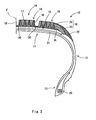
- a thin film layer 30 may be provided in the lower part of each base layer 23 (an inside in the radial direction) and each base layer 23 may be provided continuously through the thin film layer 30.
- the base layer 23 is thus provided continuously so that the following advantages can be obtained.
- a rubber sheet constituting the tread rubber layer 16 is subjected to extrusion molding. More specifically, a rubber constituting the cap layer 24 and a rubber constituting the base layer 23 are fed separately to one die plate and are extruded at the same time. Thus, the rubber sheet constituting the tread rubber layer 16 is formed.
- the base layer 23 is continuously provided through the thin film layer 30, accordingly, there is an advantage that a molding work using the die plate can easily be carried out.
- the thin film layer 30 is provided so that the rate of the area of the base layer 23 over the section of the tread layer 16 is increased and the heat generation of the tyre 10 can be thus suppressed still more. As a result, it is possible to enhance a durability at a high speed of the tyre 10.
- Table 1 shows the result of the execution of a comparison test over a conventional tyre (comparative examples 1 to 3) for a rolling resistance and an electric resistance value in a tyre according to each of examples 1 to 6 of the present invention.
- the electric resistance value of the tyre according to each of the examples and the comparative examples is measured based on an electric resistance test which will be described below.
- the rolling resistance value of the tyre according to each of the examples and the comparative examples is represented by an index with the rolling resistance value of the tyre according to the comparative example 1 set to be 100.
- a depth d1 of a groove is set to be 8.2 mm
- a tread rubber gauge (a thickness D of a tread rubber layer) is set to be 10.0 mm
- a cap rubber gauge (a dimension H from the base bottom portion of a base layer to a tread surface) is set to be 8.0 mm
- a base rubber gauge (a dimension h2 from the base bottom portion of the base layer to the bottom face of a tread portion) is set to be 2.0 mm
- a subtread gauge H1 is set to be 1.8 mm.
- a ratio to a tread rubber layer is 80% and a rubber hardness (JIS A hardness) is 64.
- the composition of a rubber constituting the cap layer is of a blend I type and a predetermined amount of silica is blended.
- the ratio to the tread rubber layer is 20% and the rubber hardness is 60.
- the number of convex portions is two and the number of the exposed convex portions to a tread surface is two.
- the composition of a rubber constituting the base layer is of a blend II type, and the silica is not blended but carbon black is blended at a relatively high rate.
- a ratio to a tread rubber layer is 80% and a rubber hardness (JIS A hardness) is 64.
- the composition of a rubber constituting the cap layer is of a blend I type and a predetermined amount of silica is blended.
- the ratio to the tread rubber layer is 20% and the rubber hardness is 59.
- the number of convex portions is two and the number of the exposed convex portions to a tread surface is two.
- the composition of a rubber constituting the base layer is of a blend III type, and the silica is not blended but carbon black is blended at a relatively low rate.
- a ratio to a tread rubber layer is 80% and a rubber hardness (JIS A hardness) is 64.
- the composition of a rubber constituting the cap layer is of a blend I type and a predetermined amount of silica is blended.
- the ratio to the tread rubber layer is 20% and the rubber hardness is 59.
- the number of convex portions is six and the number of the exposed convex portions to a tread surface is two.
- the composition of a rubber constituting the base layer is of a blend III type, and the silica is not blended but carbon black is blended at a relatively low rate.
- a ratio to a tread rubber layer is 80% and a rubber hardness (JIS A hardness) is 64.
- the composition of a rubber constituting the cap layer is of a blend I type and a predetermined amount of silica is blended.
- the ratio to the tread rubber layer is 20% and the rubber hardness is 59.
- the number of convex portions is ten and the number of the exposed convex portions to a tread surface is four.
- the composition of a rubber constituting the base layer is of a blend III type, and the silica is not blended but carbon black is blended at a relatively low rate.
- a ratio to a tread rubber layer is 80% and a rubber hardness (JIS A hardness) is 64.
- the composition of a rubber constituting the cap layer is of a blend I type and a predetermined amount of silica is blended.
- the ratio to the tread rubber layer is 20% and the rubber hardness is 59.
- the number of convex portions is sixteen and the number of the exposed convex portions to a tread surface is eight.
- the composition of a rubber constituting the base layer is of a blend III type, and the silica is not blended but carbon black is blended at a relatively low rate.
- a ratio to a tread rubber layer is 70% and a rubber hardness (JIS A hardness) is 64.
- the composition of a rubber constituting the cap layer is of a blend I type and a predetermined amount of silica is blended.
- the ratio to the tread rubber layer is 30% and the rubber hardness is 60.
- the number of convex portions is ten and the number of the exposed convex portions to a tread surface is four.
- the composition of a rubber constituting the base layer is of a blend II type, and the silica is not blended but carbon black is blended at a relatively high rate.
- a ratio to a tread rubber layer is 80% and a rubber hardness (JIS A hardness) is 64.
- the composition of a rubber constituting the cap layer is of a blend I type and a predetermined amount of silica is blended.
- the ratio to the tread rubber layer is 20% and the rubber hardness is 60.
- the number of convex portions is one and the number of the exposed convex portions to a tread surface is one.
- the composition of a rubber constituting the base layer is of a blend II type, and the silica is not blended but carbon black is blended at a relatively high rate.
- a ratio to a tread rubber layer is 80% and a rubber hardness (JIS A hardness) is 64.
- the composition of a rubber constituting the cap layer is of a blend I type and a predetermined amount of silica is blended.
- the ratio to the tread rubber layer is 20% and the rubber hardness is 59.
- the number of convex portions is one and the number of the exposed convex portions to a tread surface is one.
- the composition of a rubber constituting the base layer is of a blend III type, and the silica is not blended but carbon black is blended at a relatively low rate.
- a ratio to a tread rubber layer is 70% and a rubber hardness (JIS A hardness) is 64.
- the composition of a rubber constituting the cap layer is of a blend I type and a predetermined amount of silica is blended.
- the ratio to the tread rubber layer is 30% and the rubber hardness is 66, and the base layer is extremely harder than that in each of the other examples and comparative examples.
- the number of convex portions is ten and the number of the exposed convex portions to a tread surface is four.
- the composition of a rubber constituting the base layer is of a blend IV type, and the silica is not blended but carbon black is blended at a relatively high rate.
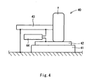
- an apparatus 40 comprises an insulating plate 41 which is grounded, a metal plate 42 provided on the insulating plate 41, a tyre attaching shaft 43 for holding a tyre T to be a specimen (more specifically, the tyre according to each of the examples and the comparative examples), and an electric resistance measuring device 44.
- the tyre attaching shaft 43 is formed by a conductor.
- An electric resistance value test for the tyre T is carried out by measuring the electric resistance value of a tyre/rim Assy in accordance with JATMA rules.
- a lubricant or dirt is previously eliminated sufficiently from the surface of the tyre T and the tyre T is fully dried.
- a rim is formed by a conductor and is adapted to a size (225/55R16) of the tyre according to each of the examples and the comparative examples. In the test, the rim is formed of an aluminum alloy and has a size of 16 X 7 - JJ.
- the internal pressure of the tyre T is set to be 200 kPa.
- a load to be 80% of a maximum load capacity according to a standard (5.3 kN in the test) is applied to the tyre T.
- a temperature in a test environment (a temperature in a test room) is set to be 25°C and a humidity is set to be 50%.
- the metal plate 42 has a surface polished smoothly, and an electric resistance value thereof is set to be equal to or smaller than 10 ⁇ .
- the insulating plate 41 has an electric resistance value set to be equal to or greater than 10 12 ⁇ .
- the measuring range of the electric resistance measuring device 44 is set to be 10 3 to 1.6 X 10 16 ⁇ and a test voltage (an applied voltage) is set to be 1000 V.
- the test is carried out in the following procedure.
- the rolling resistance of the tyre T is measured by representing, as an index, the rolling resistance value of the tyre according to each of the other comparative examples and the examples with the rolling resistance value of the tyre according to the comparative example 1 set to be "100".
- a test speed is set to be 40 km/h, 80 km/h and 120 km/h, and a mean value of numeric values obtained by the measurement at respective speeds is employed as the index of the rolling resistance value. This index indicates that the rolling resistance is increased with an increase in the value.
- Example 3 Cap layer Blend I Blend I Blend I Blend I Blend I Blend I Blend I Ratio (%) 8 0 8 0 8 0 8 0 8 0 7 0 8 0 8 0 7 0 Rubber hardness (JISA) 6 4 6 4 6 4 6 4 6 4 6 4 6 4 6 4 6 4 Base layer Blend II Large amount of carbon Blend III Small amount of carbon Blend III Small amount of carbon Blend III Small amount of carbon Blend II Large amount of carbon Blend II Large amount of carbon Blend III Small amount of carbon Blend IV Large amount of carbon Ratio (%) 2 0 2 0 2 0 2 0 2 0 2 0 3 0 2 0 2 0 3 0 Rubber hardness (JISA) 6 0 5 9 5 9 5 9 6 0 6 0 5 9 6 6 Number convex portions 2 2 6 1 0 1 6 1 0 1 1 1 0 Number of exposures to surface 2 2 2 4 8 4 1 1 4 Rolling resitance index 1 0 0 9 7 9 5 9 4 9 2 9 8 1
- a tyre having a large amount of carbon black to be blended has an excellent conductiveness, and therefore, has a small electric resistance value and a high rolling resistance.
- the amount of carbon black to be blended is increased, moreover, the conductiveness is enhanced. Even if the number of the exposed convex portions is small, therefore, an excellent conductiveness is obtained.
- the conductiveness is enhanced and the rolling resistance is also reduced with an increase in the number of the exposed convex portions. It can be supposed that the foregoing is caused by a reduction in an energy loss during the rolling of the tyre because of a relative increase in the volume ratio of the base layer.
Landscapes
- Engineering & Computer Science (AREA)
- Mechanical Engineering (AREA)
- Tires In General (AREA)
Claims (3)
- Luftreifen (10) mit einer Lauffläche (17), die eine Basisschicht (23), die an einer Innenseite in einer radialen Richtung vorgesehen ist, und eine Deckschicht (24) aufweist, die an einer Außenseite in der radialen Richtung vorgesehen ist und mit Rillen (18) an einer Außenumfangsfläche, die eine Laufflächen-Oberfläche (17) bildet, versehen ist, wodurch ein Laufflächenprofil gebildet ist,
wobei die Basisschicht (23) mit einer Vielzahl von sich in Umfangsrichtung erstreckenden, kreisförmigen, konvexen Abschnitten (26) versehen ist, die in einer axialen Richtung angeordnet sind und die in der radialen Richtung vorstehen, wobei zumindest einer der sich in Umfangsrichtung erstreckenden, kreisförmigen, konvexen Abschnitte (26) im nicht gebrauchten Reifenzustand zu der Laufflächen-Oberfläche (17) hin frei liegt, und wobei die Rillen (18) derart vorgesehen sind, dass eine Vielzahl von sich in Umfangsrichtung erstreckenden, kreisförmigen Landabschnitten (19) an der Außenumfangsfläche gebildet ist,
dadurch gekennzeichnet, dass eine Vielzahl von sich in Umfangsrichtung erstreckenden, kreisförmigen, konvexen Abschnitten (26) in jedem der sich in Umfangsrichtung erstreckenden, kreisförmigen Landabschnitten (19) vorgesehen ist, und
die sich in Umfangsrichtung erstreckenden, kreisförmigen, konvexen Abschnitte (26) in jedem der sich in Umfangsrichtung erstreckenden, kreisförmigen Landabschnitten (19) im nicht gebrauchten Reifenzustand zu der Laufflächen-Oberfläche (17) hin frei liegt. - Luftreifen nach Anspruch 1,
wobei die Deckschicht Silica enthält, und wobei die Basisschicht (23) kein Silica enthält. - Luftreifen nach Anspruch 1,
wobei die Basisschicht (23) eine Härte aufweist, die kleiner ist als die der Deckschicht (24), und wobei die Basisschicht (23) eine JIS A Härte von 55 bis 65 aufweist.
Applications Claiming Priority (2)
| Application Number | Priority Date | Filing Date | Title |
|---|---|---|---|
| JP2003310962 | 2003-09-03 | ||
| JP2003310962 | 2003-09-03 |
Publications (2)
| Publication Number | Publication Date |
|---|---|
| EP1512554A1 EP1512554A1 (de) | 2005-03-09 |
| EP1512554B1 true EP1512554B1 (de) | 2012-05-02 |
Family
ID=34131832
Family Applications (1)
| Application Number | Title | Priority Date | Filing Date |
|---|---|---|---|
| EP04016028A Expired - Lifetime EP1512554B1 (de) | 2003-09-03 | 2004-07-07 | Luftreifen |
Country Status (3)
| Country | Link |
|---|---|
| US (1) | US7334618B2 (de) |
| EP (1) | EP1512554B1 (de) |
| CN (1) | CN100333928C (de) |
Families Citing this family (18)
| Publication number | Priority date | Publication date | Assignee | Title |
|---|---|---|---|---|
| JP4342874B2 (ja) * | 2003-08-20 | 2009-10-14 | 住友ゴム工業株式会社 | 空気入りタイヤ |
| US20080216930A1 (en) * | 2007-03-05 | 2008-09-11 | Christopher John Valentine | Tyre with rubber tread which contains internal circumferential rubber stabilizer bars |
| DE102007023907A1 (de) * | 2007-05-23 | 2008-12-04 | Kreyer, Norbert, Dipl.-Ing. | Radaufhängung mit Sturzverstellung |
| DE102007025116A1 (de) | 2007-05-30 | 2008-12-04 | Continental Aktiengesellschaft | Fahrzeugluftreifen |
| US20100077641A1 (en) * | 2008-10-01 | 2010-04-01 | Greenwald Richard L | Placard holder |
| US20100154948A1 (en) * | 2008-12-22 | 2010-06-24 | Goodyear Tire & Rubber Company | Tire tread with groove reinforcement |
| RU2478484C1 (ru) * | 2008-12-23 | 2013-04-10 | Пирелли Тайр С.П.А. | Шина для колес транспортных средств, содержащая протекторный браслет, защищенный от искажений в канавках протектора |
| FR2954223B1 (fr) * | 2009-12-22 | 2016-01-01 | Michelin Soc Tech | Pneumatique ayant une bande de roulement perfectionnee |
| JP4611451B1 (ja) | 2010-06-09 | 2011-01-12 | 東洋ゴム工業株式会社 | 空気入りタイヤ |
| US9283817B2 (en) | 2011-11-22 | 2016-03-15 | The Goodyear Tire & Rubber Company | Stiffness enhanced tread |
| US20140034199A1 (en) * | 2012-07-31 | 2014-02-06 | Bridgestone Americas Tire Operations, Llc | Tire with laminate |
| JP6051072B2 (ja) * | 2013-02-22 | 2016-12-21 | 東洋ゴム工業株式会社 | 空気入りタイヤ |
| MX2016008277A (es) * | 2013-12-23 | 2016-09-08 | Bridgestone Americas Tire Operations Llc | Llanta con banda de rodadura reforzada. |
| EP3208110B1 (de) * | 2016-02-17 | 2018-08-15 | Nexen Tire Corporation | Reifenlauffläche und luftreifen |
| WO2018002488A1 (fr) * | 2016-06-30 | 2018-01-04 | Compagnie Generale Des Etablissements Michelin | Pneumatique avec une bande de roulement comportant des éléments de renforcement |
| FR3059943A1 (fr) | 2016-12-13 | 2018-06-15 | Compagnie Generale Des Etablissements Michelin | Pneumatique avec une bande de roulement comportant des elements de renforcement |
| EP3645236B1 (de) * | 2017-06-30 | 2021-04-07 | Compagnie Générale des Etablissements Michelin | Extrusionskopf mit kanälen zur herstellung von einsätzen in einem profilband zur herstellung eines luftreifens und entsprechendes extrusionsverfahren |
| US20190275841A1 (en) * | 2018-03-07 | 2019-09-12 | Bridgestone Americas Tire Operations, Llc | Tire with evolving tread |
Family Cites Families (13)
| Publication number | Priority date | Publication date | Assignee | Title |
|---|---|---|---|---|
| US4478266A (en) | 1982-09-17 | 1984-10-23 | The Goodyear Tire & Rubber Company | Composite tread having good traction and reduced rolling resistance upon wear |
| JP3477297B2 (ja) | 1994-12-21 | 2003-12-10 | 住友ゴム工業株式会社 | 空気入りタイヤ |
| DE4447823B4 (de) | 1994-12-21 | 2007-07-26 | Dunlop Gmbh | Fahrzeugreifen und Verfahren zu seiner Herstellung |
| DE69617615T2 (de) * | 1995-12-22 | 2002-08-08 | Bridgestone Corp., Tokio/Tokyo | Luftreifen |
| DE59600109D1 (de) * | 1996-03-29 | 1998-04-09 | Continental Ag | Fahrzeugluftreifen |
| EP0847880B1 (de) * | 1996-10-17 | 2002-12-18 | Sumitomo Rubber Industries Limited | Luftreifen |
| US6336486B1 (en) * | 1997-04-04 | 2002-01-08 | Bridgestone Corporation | Pneumatic radical tire having cap base tread |
| JPH11115414A (ja) * | 1997-10-09 | 1999-04-27 | Bridgestone Corp | 空気入りタイヤおよびその製造方法 |
| JP2000016010A (ja) * | 1998-07-06 | 2000-01-18 | Sumitomo Rubber Ind Ltd | 空気入りタイヤ |
| JP2000079805A (ja) * | 1998-09-07 | 2000-03-21 | Sumitomo Rubber Ind Ltd | 空気入りタイヤ |
| DE60014263T2 (de) | 1999-07-13 | 2005-02-03 | Bridgestone Corp. | Gummimischung und Reifen mit derselben Mischung |
| JP4709449B2 (ja) | 2001-09-28 | 2011-06-22 | 住友ゴム工業株式会社 | 空気入りタイヤ |
| JP4342874B2 (ja) * | 2003-08-20 | 2009-10-14 | 住友ゴム工業株式会社 | 空気入りタイヤ |
-
2004
- 2004-07-01 US US10/880,514 patent/US7334618B2/en not_active Expired - Fee Related
- 2004-07-07 EP EP04016028A patent/EP1512554B1/de not_active Expired - Lifetime
- 2004-07-30 CN CNB2004100557736A patent/CN100333928C/zh not_active Expired - Fee Related
Also Published As
| Publication number | Publication date |
|---|---|
| EP1512554A1 (de) | 2005-03-09 |
| US7334618B2 (en) | 2008-02-26 |
| CN1590139A (zh) | 2005-03-09 |
| CN100333928C (zh) | 2007-08-29 |
| US20050045258A1 (en) | 2005-03-03 |
Similar Documents
| Publication | Publication Date | Title |
|---|---|---|
| EP1512554B1 (de) | Luftreifen | |
| EP1508457B1 (de) | Luftreifen | |
| JP4392444B2 (ja) | 空気入りタイヤ及びその製造方法 | |
| US7770618B2 (en) | Pneumatic tire with electrically conductive helical path | |
| US9370909B2 (en) | Pneumatic tire and production method therefor | |
| KR101587310B1 (ko) | 공기 타이어 및 그 제조 방법 | |
| US9150052B2 (en) | Pneumatic tire | |
| EP2487051B1 (de) | Luftreifen | |
| JP5266132B2 (ja) | 空気入りタイヤ | |
| JP2010115935A (ja) | 空気入りタイヤ及びその製造方法 | |
| JP5624369B2 (ja) | 空気入りタイヤ及びその製造方法 | |
| EP3421268B1 (de) | Reifen für ein zweirädriges automobiles fahrzeug | |
| US20160159168A1 (en) | Pneumatic Tire | |
| EP1010553B1 (de) | Luftreifen | |
| JP2005096747A (ja) | 空気入りタイヤ | |
| EP3388253B1 (de) | Reifen für ein zweirädriges automobiles fahrzeug | |
| GB2349367A (en) | Pneumatic tyre | |
| EP3636454B1 (de) | Reifen | |
| JPH05254308A (ja) | 空気入りラジアルタイヤ | |
| EP1182060B1 (de) | Luftreifen | |
| EP3251876B1 (de) | Luftreifen | |
| JP4571664B2 (ja) | 空気入りタイヤ及びその製造方法 | |
| EP1772294B1 (de) | Motorradluftreifen | |
| JP7102908B2 (ja) | 空気入りタイヤ | |
| US20240217269A1 (en) | Tire |
Legal Events
| Date | Code | Title | Description |
|---|---|---|---|
| PUAI | Public reference made under article 153(3) epc to a published international application that has entered the european phase |
Free format text: ORIGINAL CODE: 0009012 |
|
| AK | Designated contracting states |
Kind code of ref document: A1 Designated state(s): AT BE BG CH CY CZ DE DK EE ES FI FR GB GR HU IE IT LI LU MC NL PL PT RO SE SI SK TR |
|
| AX | Request for extension of the european patent |
Extension state: AL HR LT LV MK |
|
| 17P | Request for examination filed |
Effective date: 20050413 |
|
| AKX | Designation fees paid |
Designated state(s): DE FR GB |
|
| 17Q | First examination report despatched |
Effective date: 20100512 |
|
| REG | Reference to a national code |
Ref country code: DE Ref legal event code: R079 Ref document number: 602004037572 Country of ref document: DE Free format text: PREVIOUS MAIN CLASS: B60C0011180000 Ipc: B60C0011000000 |
|
| GRAP | Despatch of communication of intention to grant a patent |
Free format text: ORIGINAL CODE: EPIDOSNIGR1 |
|
| RIC1 | Information provided on ipc code assigned before grant |
Ipc: B60C 19/08 20060101ALI20111213BHEP Ipc: B60C 11/00 20060101AFI20111213BHEP |
|
| RIN1 | Information on inventor provided before grant (corrected) |
Inventor name: SUZUKI, KAZUYA C/O SUMITOMO RUBBER INDUSTRIES, LT |
|
| GRAS | Grant fee paid |
Free format text: ORIGINAL CODE: EPIDOSNIGR3 |
|
| GRAA | (expected) grant |
Free format text: ORIGINAL CODE: 0009210 |
|
| AK | Designated contracting states |
Kind code of ref document: B1 Designated state(s): DE FR GB |
|
| REG | Reference to a national code |
Ref country code: GB Ref legal event code: FG4D |
|
| REG | Reference to a national code |
Ref country code: DE Ref legal event code: R096 Ref document number: 602004037572 Country of ref document: DE Effective date: 20120621 |
|
| PLBE | No opposition filed within time limit |
Free format text: ORIGINAL CODE: 0009261 |
|
| STAA | Information on the status of an ep patent application or granted ep patent |
Free format text: STATUS: NO OPPOSITION FILED WITHIN TIME LIMIT |
|
| 26N | No opposition filed |
Effective date: 20130205 |
|
| GBPC | Gb: european patent ceased through non-payment of renewal fee |
Effective date: 20120802 |
|
| REG | Reference to a national code |
Ref country code: DE Ref legal event code: R097 Ref document number: 602004037572 Country of ref document: DE Effective date: 20130205 |
|
| PG25 | Lapsed in a contracting state [announced via postgrant information from national office to epo] |
Ref country code: GB Free format text: LAPSE BECAUSE OF NON-PAYMENT OF DUE FEES Effective date: 20120802 |
|
| PGFP | Annual fee paid to national office [announced via postgrant information from national office to epo] |
Ref country code: FR Payment date: 20130724 Year of fee payment: 10 |
|
| REG | Reference to a national code |
Ref country code: FR Ref legal event code: ST Effective date: 20150331 |
|
| PG25 | Lapsed in a contracting state [announced via postgrant information from national office to epo] |
Ref country code: FR Free format text: LAPSE BECAUSE OF NON-PAYMENT OF DUE FEES Effective date: 20140731 |
|
| PGFP | Annual fee paid to national office [announced via postgrant information from national office to epo] |
Ref country code: DE Payment date: 20180626 Year of fee payment: 15 |
|
| REG | Reference to a national code |
Ref country code: DE Ref legal event code: R119 Ref document number: 602004037572 Country of ref document: DE |
|
| PG25 | Lapsed in a contracting state [announced via postgrant information from national office to epo] |
Ref country code: DE Free format text: LAPSE BECAUSE OF NON-PAYMENT OF DUE FEES Effective date: 20200201 |