EP1511593B1 - Verfahren und vorrichtung zur gasstromverwaltung in einem aufschmelzlötofen - Google Patents
Verfahren und vorrichtung zur gasstromverwaltung in einem aufschmelzlötofen Download PDFInfo
- Publication number
- EP1511593B1 EP1511593B1 EP03734183A EP03734183A EP1511593B1 EP 1511593 B1 EP1511593 B1 EP 1511593B1 EP 03734183 A EP03734183 A EP 03734183A EP 03734183 A EP03734183 A EP 03734183A EP 1511593 B1 EP1511593 B1 EP 1511593B1
- Authority
- EP
- European Patent Office
- Prior art keywords
- gas
- solder reflow
- reflow oven
- oven
- chamber
- Prior art date
- Legal status (The legal status is an assumption and is not a legal conclusion. Google has not performed a legal analysis and makes no representation as to the accuracy of the status listed.)
- Expired - Lifetime
Links
- 238000000034 method Methods 0.000 title claims description 59
- 239000007789 gas Substances 0.000 claims description 151
- 229910000679 solder Inorganic materials 0.000 claims description 59
- 230000008569 process Effects 0.000 claims description 44
- 239000011261 inert gas Substances 0.000 claims description 30
- 238000001914 filtration Methods 0.000 claims description 21
- 239000000356 contaminant Substances 0.000 claims description 19
- QVGXLLKOCUKJST-UHFFFAOYSA-N atomic oxygen Chemical compound [O] QVGXLLKOCUKJST-UHFFFAOYSA-N 0.000 claims description 15
- 239000001301 oxygen Substances 0.000 claims description 15
- 229910052760 oxygen Inorganic materials 0.000 claims description 15
- 239000003039 volatile agent Substances 0.000 claims description 5
- 239000007788 liquid Substances 0.000 claims description 3
- 230000008859 change Effects 0.000 claims description 2
- 238000001764 infiltration Methods 0.000 claims description 2
- 230000008595 infiltration Effects 0.000 claims description 2
- 230000002829 reductive effect Effects 0.000 claims description 2
- 239000012530 fluid Substances 0.000 claims 3
- 230000000740 bleeding effect Effects 0.000 claims 1
- 238000007664 blowing Methods 0.000 claims 1
- 238000007599 discharging Methods 0.000 claims 1
- 239000012535 impurity Substances 0.000 claims 1
- IJGRMHOSHXDMSA-UHFFFAOYSA-N Atomic nitrogen Chemical compound N#N IJGRMHOSHXDMSA-UHFFFAOYSA-N 0.000 description 18
- 230000004907 flux Effects 0.000 description 13
- 238000009833 condensation Methods 0.000 description 12
- 230000005494 condensation Effects 0.000 description 12
- 238000001816 cooling Methods 0.000 description 11
- 229910052757 nitrogen Inorganic materials 0.000 description 9
- 230000004888 barrier function Effects 0.000 description 8
- 238000004140 cleaning Methods 0.000 description 6
- 238000000926 separation method Methods 0.000 description 5
- 238000010586 diagram Methods 0.000 description 4
- 238000010438 heat treatment Methods 0.000 description 4
- 238000002156 mixing Methods 0.000 description 4
- 239000000853 adhesive Substances 0.000 description 3
- 230000001070 adhesive effect Effects 0.000 description 3
- 238000006243 chemical reaction Methods 0.000 description 3
- 238000007726 management method Methods 0.000 description 3
- 239000002245 particle Substances 0.000 description 3
- 239000011230 binding agent Substances 0.000 description 2
- 230000007246 mechanism Effects 0.000 description 2
- 238000005457 optimization Methods 0.000 description 2
- 238000005476 soldering Methods 0.000 description 2
- 230000009471 action Effects 0.000 description 1
- 238000013459 approach Methods 0.000 description 1
- 239000007795 chemical reaction product Substances 0.000 description 1
- 231100000481 chemical toxicant Toxicity 0.000 description 1
- 150000001875 compounds Chemical class 0.000 description 1
- 239000012141 concentrate Substances 0.000 description 1
- 238000011109 contamination Methods 0.000 description 1
- 238000000354 decomposition reaction Methods 0.000 description 1
- 230000003247 decreasing effect Effects 0.000 description 1
- 230000001419 dependent effect Effects 0.000 description 1
- 230000006866 deterioration Effects 0.000 description 1
- 238000007865 diluting Methods 0.000 description 1
- 238000009826 distribution Methods 0.000 description 1
- 230000000694 effects Effects 0.000 description 1
- 238000004134 energy conservation Methods 0.000 description 1
- 230000002708 enhancing effect Effects 0.000 description 1
- 230000002401 inhibitory effect Effects 0.000 description 1
- 238000002955 isolation Methods 0.000 description 1
- 239000000463 material Substances 0.000 description 1
- 239000002609 medium Substances 0.000 description 1
- 239000002184 metal Substances 0.000 description 1
- 230000005012 migration Effects 0.000 description 1
- 238000013508 migration Methods 0.000 description 1
- 239000000203 mixture Substances 0.000 description 1
- 230000036961 partial effect Effects 0.000 description 1
- 238000010926 purge Methods 0.000 description 1
- 239000012857 radioactive material Substances 0.000 description 1
- 229920006395 saturated elastomer Polymers 0.000 description 1
- 230000035945 sensitivity Effects 0.000 description 1
- 239000003440 toxic substance Substances 0.000 description 1
- 238000012546 transfer Methods 0.000 description 1
- 239000006163 transport media Substances 0.000 description 1
- 238000009736 wetting Methods 0.000 description 1
Images




Classifications
-
- B—PERFORMING OPERATIONS; TRANSPORTING
- B23—MACHINE TOOLS; METAL-WORKING NOT OTHERWISE PROVIDED FOR
- B23K—SOLDERING OR UNSOLDERING; WELDING; CLADDING OR PLATING BY SOLDERING OR WELDING; CUTTING BY APPLYING HEAT LOCALLY, e.g. FLAME CUTTING; WORKING BY LASER BEAM
- B23K1/00—Soldering, e.g. brazing, or unsoldering
- B23K1/012—Soldering with the use of hot gas
-
- Y—GENERAL TAGGING OF NEW TECHNOLOGICAL DEVELOPMENTS; GENERAL TAGGING OF CROSS-SECTIONAL TECHNOLOGIES SPANNING OVER SEVERAL SECTIONS OF THE IPC; TECHNICAL SUBJECTS COVERED BY FORMER USPC CROSS-REFERENCE ART COLLECTIONS [XRACs] AND DIGESTS
- Y10—TECHNICAL SUBJECTS COVERED BY FORMER USPC
- Y10S—TECHNICAL SUBJECTS COVERED BY FORMER USPC CROSS-REFERENCE ART COLLECTIONS [XRACs] AND DIGESTS
- Y10S55/00—Gas separation
- Y10S55/29—Air curtains
Definitions
- This invention relates generally to the field of reflow soldering ovens, and, more particularly to a method and an apparatus for removing flux vapors and other volatile contaminants from the atmosphere of such ovens.
- a prior art example is disclosed in EP-A-0 999 007 .
- Printed circuit boards are commonly fabricated using the reflow solder technique.
- a paste containing solder particles mixed with flux, adhesives, binders, and other components is applied to selected areas of a printed circuit board.
- Electronic devices are pressed into the applied solder paste.
- Adhesives in the paste hold the devices to the printed circuit board.
- a conveyor within a reflow oven tunnel carries the printed circuit board and devices through regions of varying temperatures within the oven, each region performing a specific step in the reflow process. Generally an initial (preheat) region will bring the circuit board and devices to a predetermined temperature for flux reaction. A second (soak) region will maintain this reaction temperature for a predetermined time. Flux in the solder paste reacts with the contacts to remove oxides and to enhance wetting.
- a third (reflow) region will heat the circuit boards and devices to a temperature sufficient to cause the solder particles in the paste to melt. Molten solder wets metal contacts on the devices and printed circuit board. The conveyor moves the heated printed circuit board to a fourth (cooling) region of the oven where the molten solder solidifies forming a completed electronic circuit.
- the reaction of the flux with the contacts liberates vapors. Further, heat within the oven vaporizes flux as well as adhesives, binders, and other components of the solder paste, devices, and circuit boards. The vapors from these materials accumulate within the oven leading to a number of problems. If the vapors migrate to a cooler region they will condense on the circuit boards, contaminating the boards and making subsequent cleaning steps necessary. The vapors will also condense on cooler surfaces within the oven, clogging gas orifices, gumming up moving parts, and creating a fire hazard. This condensate may also drip onto subsequent circuit boards destroying them, or making subsequent cleaning steps necessary. In addition, condensed vapors may contain corrosive and toxic chemicals, which can damage equipment and create a hazard to personnel.
- volatile contaminants The flux vapors and other volatile compounds generated by the reflow operation collectively are referred to in this application as "volatile contaminants.” It is understood that this term is intended to encompass all reaction products released when the printed circuit board is heated, including flux vapors, vapors from all other components of the solder paste, as well as all vapors out-gassed from the printed circuit board and the electronic devices.
- Volatile contaminants can be flushed from the oven by providing a continuous supply of clean gas. This is commonly done in machine operating with air as the process gas by drawing fresh air in both ends of the oven and exhausting the air along with volatile contaminants from the inner regions of the oven as described in U.S. Pat. No. 5,345,061 by Chanasyk et al. This is not an ideal solution for the cases where the oven must be filled with a substantially inert gas, for example nitrogen. Generating additional inert gas in volumes adequate to flush these ovens (2000cfh or more) is expensive.
- the prior art involves removal, filtration, and reintroduction of inert gas to the oven, however, they fail to address the complex gas flow patterns necessary to maintain a clean, substantially inert atmosphere while also maintaining the precise temperature profile required by the reflow process.
- Flows for substantially inert gas optimization need to purge the entire tunnel of air and pressurize the center such that flows are out both ends impeding any flow of outside environment in.
- Flows optimized for substantially inert gas containment are not compatible with control of volatile contaminant condensation as all volatile contaminants pass through the coolest regions of the oven where they condense before they reach the exhaust, and also may not be optimized for zone temperature definition.
- the present invention introduces an substantially inert gas, for example nitrogen, in a reflow oven tunnel at predetermined points to influence the oven tunnel gas flow and to dilute and expel excess oxygen from the system.
- Tunnel gas is ducted from the tunnel at selected points to a flux separation system to be cleaned, for example remove flux vapors, and returned to the tunnel for recirculation, thereby conserving the substantially inert gas and maintaining a low oxygen environment.
- the substantially inert gas is introduced in amounts larger than required to create and maintain tunnel gas flow.
- the system maintains sufficient pressure to supply end baffle boxes with clean gas to create a gas barrier to effectively seal off the tunnel ends from air infiltration or migration into the tunnel making the system insensitive to external pressure and/or temperature variations.
- the substantially inert gas such as nitrogen, is cold relative to the tunnel gas at the point of introduction.
- the cold gas will mix with the hotter gas thereby absorbing excess heat for better zone temperature control.
- the cold source gas mixing with the hotter gas causes an expansion of the tunnel gas.
- the tunnel gas is drawn in both directions by the tunnel gas outlets of the recirculation system.
- substantially inert gas is introduced into the pre-heat and/or soak zones of the tunnel mixing with the tunnel gas.
- the mixed gas primarily flows toward the reflow zone to prevent condensation and for zone temperature definition. Some mixed gas splits and flows toward select outlets in the pre-heat and soak zones to be ducted to the flux separation system for cleaning prior to recirculation.
- Additional inert gas is introduced into the cooling zone of the tunnel mixing with the tunnel gas and flowing back toward the reflow zone. The counter flowing gases converge at the boundary of the high temperature region and a cooling region to mix and exit the tunnel toward the flux separation system for cleaning and recirculation.
- the amount of substantially inert gas can be varied at each introduction inlet to account for gas expansion differentials and flow direction.
- Recirculated gas can be reintroduced at points in the tunnel to cause flow generally from colder areas into hotter areas, with maximum flow out of the cool zones and flow out of a zone where flux build up problems are the worst.
- Recirculated flows are introduced into the baffle boxes for pressure control, baffling, and exhaust. The system exhausts through the baffle boxes more gas than input to account for expansion of the substantially inert gas due to heating.
- the exhaust system defined by the baffle boxes, recirculated gas and exhaust hoods, generally are not be used to remove contamination from the system, but only to remove the excess expansion gas, which has been cleaned, recirculated, used to pressurize the baffle box, and allowed to draft out of the baffle space to the exhaust hood, thereby inhibiting the in-flow of oxygen contained in the outside air.
- the exhaust hoods are located above the tunnel ends outside of the baffle boxes. The exhaust hoods can be ducted to the customers facility exhaust.
- the flow from the recirculation system into the baffle boxes are preferably set at a flow equal to the substantially inert gas input plus expansion to keep the pressure inside the tunnel constant, with no-flow through the baffle area and into the oven tunnel.
- Baffle boxes are, preferably, incorporated at both ends of the oven to form isolation zones between the constantly changing pressure and drafts of the factory and the expanding and contracting gas flows within the tunnel. Since the baffle box preferably is pressurized by clean recirculated gas at a rate slightly higher than the substantially inert gas, such as nitrogen, input rate plus an expansion factor, the recirculated gas is metered through a series of small orifices onto a flat angled surface to create a series of low-level laminar flows. These flows come from both top and bottom of the reflow oven. The outer most flows are, preferably, allowed to draft out of the oven to be picked up by a low level flow exhaust hoods at the ends of the tunnel constituting the entire exhaust volume.
- substantially inert gas such as nitrogen, input rate plus an expansion factor
- baffle boxes are supplied with recirculated gas is significant in several ways. It is preferred that no inert gas is dumped to the factory essentially unused and un-expanded; thus decreasing inert gas consumption. There is also no tunnel gas migrating through the baffle area disturbing the desired flow. This action also de-couples the flow of the baffle boxes from the flow in the tunnel in order to reduce the buoyancy driven mixing at the tunnel ends. Also since this recirculated gas is heated and ducted to top and bottom of both tunnel ends, the buoyancy effect is much reduced.
- low oxygen content in the tunnel gas is desired to improve system performance, for example filtration of contaminants.
- low flow valves are employed to bleed low volumes of air into the tunnel at one or more pre-selected locations, thereby controlling the parts per million of oxygen mixed with the tunnel gas.
- Flows optimized for volatile contaminant control are designed to move gas from cooler toward hotter regions of the tunnel to eliminate any condensation, and with a high exhaust throughput to expel contaminants.
- the most important flow in this scheme is the flow through the cool region toward the hotter region to eliminate any counter flow of volatile contaminants.
- Gas flow separation between zones in the tunnel allows temperature separation between those zones. Controlling the direction of tunnel flows from cooler to hotter can not only allow higher zone differentials, but can also inhibit condensation in the cooler areas.
- Nitrogen or other gases are used to inert the tunnel by diluting and displacing oxygen. For example, nitrogen input and expansion in the tunnel pressurizes and isolates the tunnel from outside pressure fluctuations. Nitrogen is used to create flows and pressure in the baffle areas to inhibit the reentry of oxygen.
- Hot gas is the heat transfer medium of the convection oven. Gas recirculation in a zone carries the particular heat energy of that zone to the printed circuit board.
- Hot gas is the transport media for the volatile contaminants from the tunnel to an exhausting or filtering mechanism. Therefore, inert ovens generally have several features within them to provide and maintain the inert atmosphere. These include: Process Gas Input and Distribution system, Oven Gas Circulation system, Condense and Filter system, Gas Reintroduction system, Tunnel End Baffle system, and the Exhaust system. Gas introduced to inert the oven will pass through and impact the effectiveness all of these systems. Therefore, to be most effective, these systems must be combined into one comprehensive gas management system.
- Reflow oven 2 includes two vertically opposed rows of temperature cells 4 forming the process tunnel 42, which is sectioned off into a high temperature region 22 and a cooling region 24.
- a conveying mechanism 44 for carrying objects to be heated, for example printed circuit boards, runs through the process tunnel 42.
- a process gas reservoir 46 for storing an substantially inert gas, for example nitrogen, can be provided to supply the process tunnel 42 with a particular process gas.
- Selected inlet ports 6 are piped from the process gas reservoir 46 through flow meters 56. Substantially inert gas enters the process tunnel 42 through the temperature cells 4 (described in detail below with respect to FIG. 2 ).
- the volume of substantially inert gas through each of these flow meters 56 is set at a rate to produce the desired pressure and flow direction in that portion of the process tunnel 42. Pressure is caused not only by the introduction of this process gas, but also by the expansion of the cold gas due to heat, as described in FIG. 2 , in the process tunnel 42.
- the location of these selected inlet ports 6 are such that the flows caused in the process tunnel 42 are generally from the cool region 24 to the high temperature region 22, and from cooler to hotter areas within the high temperature region, to impede the flow of volatile laden gas from migrating to the cooler regions where it will condense. This also concentrates the volatile laden gas in regions where the outlets 8 and barrier vent 32 connect to the condensation and filtration chamber 34 (described in greater detail in FIG.
- the barrier vent 32 is located between the high temperature region 22 and the cooling region 24 of the oven 2.
- the barrier vent 32 allows gas from the high temperature region 22 that would otherwise migrate into the cooling region 24 to be drawn out of the process tunnel 42 into the recirculation ducting 30.
- Selected outlet ports 8 are interconnected through recirculation ducting 30 to a condensation and filtration chamber 34 (described in greater detail in FIG. 3 ).
- a recirculation blower 36 located inside chamber 34 powers and controls the flow of gases within the recirculation ducting 30 to the process tunnel 42.
- Clean gas is ducted from the condensation and filtration chamber 34 to the process tunnel 42 by two separate routes, both powered by recirculation blower 36.
- the first route is into several selected inlet ports 6 with a volume bias toward the cooling region 24 such that a flow is created from the cooling region 24 to the high temperature region 22 to inhibit volatiles from the high temperature region 22 from migrating into the cooling region 24. This prevents condensation of these volatiles on cool surfaces in the cooling region 24.
- the positioning of inlet ports 6 and outlets 8 are derived from specific operating parameters.
- FIG. 2 A preferred embodiment of a temperature cell 4 of the present invention is illustrated in FIG. 2 , shown as a top and bottom pair, as described in U.S. Patent No. 5,345,061 , entitled CONVECTION/INFRARED SOLDER REFLOW APPARATUS UTILIZING CONTROLLED GAS FLOW, issued September 6, 1994.
- An inlet port 6 and an outlet port 8 are provided on each cell 4.
- the inlet port 6 is connected with a return channel 16.
- the return channel 16 is connected with a centrifugal fan 12 driven by a motor 10.
- the centrifugal fan 12 is contained within a plenum 26.
- a diffuser 14 forms the bottom surface of the plenum 26. Imbedded in the diffuser 14 is a heating element 18.
- Holes 20 are provided through the diffuser 14 and heating element 18 so that gas driven by the fan 12 exits the plenum 26 into the process tunnel 42.
- the return channel 16 has inlets 28 opening into the process tunnel 42 allowing the gas exiting the plenum 26 to return to the fan 12 and back out through the diffusers 14 and heater 18.
- the outlet port 8 is connected with the plenum 26.
- the pressure drop of the gas drawn along the return channel 16 by the fan 12 causes suction through the inlet port 6. Positive pressure within the plenum 26 forces gas out of the outlet port 8.
- the gas forced by the fan 12 is heated by the heating element 18 and heats objects, for example printed circuit boards, in the process tunnel 42 by convection.
- a low flow valve 72 is operably connected to an inlet port 6 not being used for the delivery of primary inert gas.
- Low volumes of air bleed into the tunnel at one or more pre-selected locations, thereby controlling the parts per million of oxygen mixed with the tunnel gas.
- the air bleed valves is a direct connection to an oxygen supply can be incorporated in the present system.
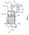
- Condensation and filtration chamber 34 used with the present invention is shown in FIG. 4 .
- An inlet port 40 in chamber 34 is connected to the oven 2 through the recirculation ducting 30.
- a recirculation blower 36 draws the tunnel gas out of the process tunnel 42 through outlet port 8 and into chamber 34 gas containing volatiles.
- the tunnel gas is drawn past several condensing plates 50 to condense the volatiles into liquid, which will run off the plates 50 into chamber 34 to be drained from the system through drain 52; or particles which will be drawn into and captured by filter 38.
- the cleaned tunnel gas is then past through recirculation blower 36 exiting the chamber through outlet port 48 and returned as recirculated gas back into process tunnel 42 through recirculation ducting 30.
- the terms clean gas and recirculated gas or decontaminated gas are used interchangeably throughout the specification, which contains substantially inert gas mixed with low levels of oxygen and other gases.
- the flow from the recirculation blower 36 is set to a pre-determined value.
- a venturi flow meter 60 and pressure transmitter 64 senses the flow.
- the value is calculated by a computer 68 such that as the filter 38 becomes saturated, flow remains constant by speeding up the recirculation blower 36 until a predetermined speed triggers a signal to provide an indication to change the filter 38.
- the tunnel end baffle boxes 54 are located both top and bottom of both ends of the process tunnel 42.
- the tunnel end baffle boxes 54 are the second route of the clean gas returning from the condensation and filtration chamber 34 through the recirculation ducting 30 to baffle inlet port 55.
- the clean gas passes through the tunnel end baffle boxes 54 then out of the oven 2 into the exhaust hood 70, as shown in FIG. 1 .
- the baffle box 54 preferably is pressurized by clean recirculated gas at a rate slightly higher than the substantially inert gas, for example nitrogen, input rate plus an expansion factor, the recirculated gas, as shown in FIG.
- the innermost flows will cause a pressurized space to keep expansion gas from the tunnel from flowing through the baffle space. Further, with all exhaust gas exiting the process tunnel 42 through the tunnel end baffle boxes 54, the flows inside the process tunnel 42 are isolated from outside influences, thereby enhancing the temperature control for the reflow process.
- FIG. 6 A further preferred embodiment of the present invention, 51, where similar components use identical reference numbers as shown in FIG. 1 is illustrated in FIG. 6 .
- the basic components of the oven 2 of FIG. 1 are employed here.
- the difference between the embodiments is the method of the introduction of the substantially inert and recirculated gas into the process tunnel 42 and the removal of tunnel gas.
- the oven 51 introduces gases directly into the process tunnel 42 bypassing the temperature cell 4, and removes gases directly from the process tunnel 42 bypassing the temperature cell 4.
- the location of these selected inlet ports 106 are such that the flows caused in the process tunnel 42 are generally from the cool region 24 to the high temperature region 22, from cooler to hotter areas within the high temperature region 22, to impede the flow of volatile laden gas from migrating to the cooler regions where it will condense.
- the method of using a tube or equivalent provides flexibility to adapt substantially all existing reflow solder ovens with a gas management system as disclosed in the alternative embodiment 2, as well as being the used in future reflow solder oven designs.
- the temperature cell 104 of the second embodiment, illustrated in FIG. 7 , shown as a top and bottom pair, is primarily the same temperature cell 4 of the first embodiment with the exception of an inlet 106.
- Inlet 106 may be provided near the return channel 16 such that gas introduced at the inlet 106 will enter the plenum 26 and be mixed with gas in the process tunnel 42.
- outlets 8, described in the preferred embodiment 2 are replaced with barrier vent 132, as shown in FIG. 6 .
- Barrier vent 132 is located in the high temperature region 22 to control the flow direction of the expanding gas from the process gas reservoir 46 and is connected to the recirculation ducting 30 for cleaning by the condensation and filtration chamber 34. Gas is condensed, filtered, and reintroduced to the process tunnel 42 is the same manner as in the first embodiment 2. Similar to inlet 106, the method of using a main return duct like barrier vent 132 provides a flexibility to adapt existing reflow solder ovens with a gas management system as well as being the used in future reflow solder oven designs.
- low oxygen content in the tunnel gas is desired to improve the system performance, for example filtration of contaminants.
- a low flow valve same as or similar to the low flow valve 72 of FIG. 3 , is operably connected to an inlet port similar to inlet port 106 used for the delivery of primary inert gas.
- Low volumes of air bleed into the tunnel at one or more pre-selected locations, thereby controlling the parts per million of oxygen mixed with the tunnel gas.
- An alternative to the air bleed valves is a direct connection to an oxygen supply.
Landscapes
- Engineering & Computer Science (AREA)
- Mechanical Engineering (AREA)
- Electric Connection Of Electric Components To Printed Circuits (AREA)
Claims (11)
- System zum Entfernen von Verunreinigungen aus einem Lötschmelzofen (2, 51), umfassend:mindestens einen Lötschmelzofenauslass (8, 32, 132), der wirksam mit dem Lötschmelzofen (2, 51) verbunden ist;mindestens einen Lötschnlelzofeneinlass (6, 106), der wirksam mit dem Lötschmelzofen (2, 51) verbunden ist;ein Gasfiltrierungsmittel (34) zum Kondensieren und Filtern von Verunreinigungen aus Lötschmelzofengasen, wobei das genannte Gasfiltrierungsmittel wirksam mit dem genannten mindestens einen Lötschmelzofenauslass (8, 32, 132) und dem genannten mindestens einen Lötschmelzofeneinlass (6, 106) verbunden ist, wobei das genannte Gasfiltrierungsmittel (34) in der Lage ist, Lötschmelzofengase aus dem Lötschmelzofen zu saugen und das verunreinigte Gas zum Wiedereinbringen in den Lötschmelzofen im Wesentlichen zu reinigen, um die Regelung des Gasstroms in dem Lötschmelzofen zu erleichtern; undgekennzeichnet durch:wobei das genannte Gasfiltrierungsmittel (34) zum Einbringen von gereinigtem Gas in das genannte Umlenkmittel (34) wirksam mit dem genannten Umlenkmittel (54) verbunden ist, um ein Unterdrucksetzungsgas zu liefern, um die im Wesentlichen undurchlässige Wand aus Gas zu bilden.ein Umlenkmittel (54) zum Bilden einer im Wesentlichen undurchlässigen Wand aus Gas, das wirksam mit mindestens einem Ende des Lötschmelzofens verbunden ist; undeinen Prozessgasbehälter (46), der wirksam direkt mit mindestens einem zusätzlichen Lötschmelzofeneinlass (6, 106) verbunden ist, wobei der genannte Prozessgasbehälter in der Lage ist, im Wesentlichen inertes Gas zu liefern, um die Regelung des Gasstroms im Lötschmelzofen zu erleichtern;
- System nach Anspruch 1, wobei der Lötschmelzofen eine Vielzahl von Zonen (22, 24, 58, 62, 66) umfasst, wobei jede der Vielzahl von Zonen mindestens eine Heizvorrichtung (18) umfasst und wobei der genannte mindestens eine Lötschmelzofeneinlass mit der mindestens einen Heizvorrichtung (18) wirksam ist.
- System nach Anspruch 2, weiter umfassend einen Strömungsmesser (56), der zwischen dem genannten Prozessgasbehälter und dem genannten mindestens einen zusätzlichen Lötschmelzofeneinlass angeordnet ist, wobei der genannte Strömungsmesser (56) in der Lage ist, das Volumen des im Wesentlichen inerten Gases in den Lötschmelzofen zu regeln, um einen gewünschten Druck und eine gewünschte Strömungsrichtung in jeder der genannten Vielzahl von Zonen zu erzeugen.
- System nach Anspruch 1, weiter umfassend ein Mikroventil (72), das wirksam mit dem genannten mindestens einen Lötschmelzofeneinlass verbunden ist, wobei das genannte Mikroventil in der Lage ist, Außenluft mit einem Mengenstrom in den Lötschmelzofen einzulassen, der ausreicht, um einen vorherbestimmten Sauerstoffgehalt im Lötschmelzofen zu erzeugen.
- System nach Anspruch 1, wobei das genannte Gasfiltrierungsmittel (34) weiter Folgendes umfasst:eine Kammer (34), mit
einem Kammereinlasskanal (40), der in Fluidverbindung mit dem genannten mindestens einen Lötschmelzofenauslass steht, und
einem Kammerauslasskanal (8), der in Fluidverbindung mit dem genannten mindestens einen Lötschmelzofeneinlass und dem genannten Umlenkmittel steht;ein Umwälzgebläse (36), das wirksam mit dem genannten Kammerereinlasskanal und dem genannten Kammerauslasskanal verbunden ist, wobei das genannte Umwälzgebläse in der Lage ist, Ofengas aus dem genannten mindestens einen Lötschmelzofenauslass und zum Filtern in die genannte Kammer zu saugen, wobei das genannte Umwälzgebläse weiter in der Lage ist, gefiltertes Gas zu dem genannten mindestens einen Lötschmelzofeneinlass und dem genannten Umlenkmittel zu blasen, um Gas zuzuführen, um die genannte im Wesentlichen undurchlässige Wand aus Gas zu bilden;eine Vielzahl von in der genannten Kammer (34) enthaltenen Kondensationsplatten (50), um flüchtige Stoffe zu Flüssigkeit zu kondensieren, die in aus dem Lötschmelzofen gesaugtem Gas enthalten sind;einen Ablauf (52), der mit der genannten Kammer (34) verbunden ist und einen Fluiddurchgang zu einem außen liegenden Ort bildet, um Flüssigkeit aus der genannten Kammer abzulassen, der von den genannten Kondensationsplatten abläuft; undeinen Filter (38), der in der genannten Kammer angeordnet ist und zwischen den genannten Kondensationsplatten (50) und dem genannten Kammerauslasskanal (8) angeordnet ist, um im Wesentlichen Verunreinigungen aus aus dem Lötschmelzofen gesaugtem Ofengas zu filtern. - System nach Anspruch 5, wobei das genannte Gasfiltrierungsmittel (34) weiter Folgendes umfasst:einen Venturi-Strömungsmesser (60), der wirksam mit dem genannten Auslasskanal (8) der Kammer (34) verbunden ist, um den Ausgangsstrom aus der genannten Kammer zu messen;einen Druckgeber (64), der wirksam mit dem genannten Venturi-Strömungsmesser (60) verbunden ist und in der Lage ist, das genannte Maß des genannten Ausgangsstroms in ein elektronisches Signal zu wandeln; undeinen Computer (68), der wirksam mit dem genannten Druckgeber und dem genannten Umwälzgebläse (36) verbunden ist, wobei der genannte Computer in der Lage ist, den Gasstrom zu berechnen und die Drehzahl des genannten Umwälzgebläses zu regeln, um einen im Wesentlichen konstanten Gasstrom im genannten Umwälzsystem aufrecht zu erhalten, wobei ein reduzierter gefilterter Gasstrom infolge Sättigung des Filters durch eine Erhöhung der Gebläsedrehzahl ausgeglichen wird.
- System nach Anspruch 6, wobei der genannte Computer (68) weiter in der Lage ist, das genannte Umwälzgebläse abzuschalten, wenn eine vorherbestimmte Gebläsedrehzahl erreicht wird, und dadurch eine Anzeige zum Wechseln des genannten Filters bereitstellt.
- System nach Anspruch 1, wobei das genannte Umlenkmittel (54) Folgendes umfasst:eine Kammer (54) mit einer Gaseintrittsöffnung zum Empfangen von umgewälztem Gas, einer Gasausblasöffnung und Seitenwänden;eine Vielzahl von Umlenkplatten (59), wobei jede der genannten Vielzahl von Umlenkplattten im Wesentlichen parallel zueinander in der genannten Kammer angeordnet ist, wobei sich die genannte Vielzahl von Umlenkplatten teilweise durch die genannte Kammer erstreckt, wobei die genannte Vielzahl von Umlenkplatten bezüglich der genannten Seitenwände abgewinkelt angeordnet ist, um die Bewegung von umgewälztem Gas durch die genannte Kammer zu verzögern;wobei jede der genannten Vielzahl von Umlenkplatten eine Kante angrenzend an eine Blendenplatte (57) und eine gegenüberliegende Kante, die in enger Nähe zur genannten Gasausblasöffnung angeordnet ist, aufweist;wobei die genannte Blendenplatte eine Vielzahl von Löchern hat, um den Strom von umgewälztem Gas an der genannten Vielzahl von Umlenkplatten vorbei zu messen; unddie genannte Gasausblasöffnung zum Ausblasen von umgewälztem Gas daraus;wobei das genannte Umlenkmittel eine Folge von laminaren Strömungen auf niedriger Ebene von der genannten gegenüberliegenden Kante der genannten Umlenkplatten in die genannten Enden des genannten Ofens erzeugt, um eine im Wesentlichen undurchlässige Wand aus umgewälztem Gas zu bilden.
- Verfahren zum Entfernen von Verunreinigungen aus einem Lötschmelzofen, der in eine Vielzahl von Temperaturzonen unterteilt ist, wobei das genannte Verfahren folgende Schritte umfasst:Fördern von zu erwärmenden Gegenständen durch den Lötschmelzofen (2, 51) von einem Eingangsende zu einem Ausgangsende;selektives Einbringen von im Wesentlichen inertem Gas von einer externen Quelle (46) in mindestens eine der Vielzahl von Temperaturzonen im Lötschmelzofen;selektives Auslassen von Lötschmelzofengas aus mindestens einer der Vielzahl von Temperaturzonen (22, 24, 58, 62, 66);im Wesentlichen Entfernen von Verunreinigungen aus dem Lötschmelzofengas;selektives Umleiten eines Anteils von im Wesentlichen gereinigtem Lötschmelzofengas zu jedem Ende des Lötschmelzofens, so dass ein Hochdruckbereich gebildet wird und im Wesentlichen die Infiltration von Luft in den Lötschmelzofen verhindert wird;selektives Einbringen eines verbleibenden Anteils des im Wesentlichen gereinigten Lötschmelzofengases in mindestens eine der Vielzahl von Temperaturzonen; undPositionieren von ausgewählten Eintragsstellen (6, 106) für im Wesentlichen inertes Gas, Austragstellen (8, 32, 132) für Lötschmelzofengas und Wiedereintragsstellen (6, 106) für im Wesentlichen gereinigtes Lötschmelzofengas, um Gasströme im Lötschmelzofen von einer kühlen Region zu einer Region mit höherer Temperatur als die kühle Region und von kühleren zu heißeren Bereichen in der Region mit höherer Temperatur zu beeinflussen, um den Strom von verunreinigtem Gas daran zu hindern, zu den kühleren Regionen zu migrieren, wo verunreinigtes Gas kondensiert.
- Verfahren nach Anspruch 9, weiter umfassend den Schritt des Einstellens des Inertgasstroms an jeder Eintragsstelle, um die Expansionsrate des Lötschmelzofengases auszugleichen.
- Verfahren nach Anspruch 9, weiter umfassend den Schritt des Auslassens von überschüssigem im Wesentlichen gereinigtem Lötschmelzofengas an jedem Ende des Lötschmelzofens.
Applications Claiming Priority (5)
| Application Number | Priority Date | Filing Date | Title |
|---|---|---|---|
| US38316502P | 2002-05-24 | 2002-05-24 | |
| US383165P | 2002-05-24 | ||
| US10/185,377 US6780225B2 (en) | 2002-05-24 | 2002-06-27 | Reflow oven gas management system and method |
| US185377 | 2002-06-27 | ||
| PCT/US2003/016528 WO2003099502A1 (en) | 2002-05-24 | 2003-05-23 | Reflow oven gas management system and method |
Publications (2)
| Publication Number | Publication Date |
|---|---|
| EP1511593A1 EP1511593A1 (de) | 2005-03-09 |
| EP1511593B1 true EP1511593B1 (de) | 2008-08-13 |
Family
ID=29552791
Family Applications (1)
| Application Number | Title | Priority Date | Filing Date |
|---|---|---|---|
| EP03734183A Expired - Lifetime EP1511593B1 (de) | 2002-05-24 | 2003-05-23 | Verfahren und vorrichtung zur gasstromverwaltung in einem aufschmelzlötofen |
Country Status (6)
| Country | Link |
|---|---|
| US (1) | US6780225B2 (de) |
| EP (1) | EP1511593B1 (de) |
| CN (1) | CN100337779C (de) |
| AU (1) | AU2003239876A1 (de) |
| DE (1) | DE60322892D1 (de) |
| WO (1) | WO2003099502A1 (de) |
Cited By (1)
| Publication number | Priority date | Publication date | Assignee | Title |
|---|---|---|---|---|
| WO2024044086A1 (en) * | 2022-08-26 | 2024-02-29 | Illinois Tool Works Inc. | Reflow oven |
Families Citing this family (80)
| Publication number | Priority date | Publication date | Assignee | Title |
|---|---|---|---|---|
| FR2860862B1 (fr) * | 2003-10-09 | 2006-08-04 | Air Liquide | Procede de traitement thermique d'une serie d'objets et appareil associe |
| TW200524496A (en) * | 2004-01-07 | 2005-07-16 | Senju Metal Industry | Reflow furnace |
| US7347354B2 (en) * | 2004-03-23 | 2008-03-25 | Intel Corporation | Metallic solder thermal interface material layer and application of the same |
| US7595967B1 (en) | 2004-09-07 | 2009-09-29 | Western Digital (Fremont), Llp | Method for fabricating a spacer layer for a magnetoresistive element |
| KR100712526B1 (ko) * | 2005-01-08 | 2007-04-30 | 삼성전자주식회사 | 반도체 칩 패키지 장치 및 그 방법 |
| JP4834559B2 (ja) * | 2005-01-17 | 2011-12-14 | 有限会社ヨコタテクニカ | リフロー炉 |
| US7914595B2 (en) * | 2005-02-07 | 2011-03-29 | Senju Metal Industry Co., Ltd. | Fume removal method for a reflow furnace and a reflow furnace |
| DE102005014291A1 (de) * | 2005-03-24 | 2006-09-28 | Basf Ag | Verfahren zur Herstellung wasserabsorbierender Polymere |
| US20060266793A1 (en) * | 2005-05-24 | 2006-11-30 | Caterpillar Inc. | Purging system having workpiece movement device |
| JP2006339314A (ja) * | 2005-05-31 | 2006-12-14 | Toshiba Corp | 加熱装置 |
| DE102005027216A1 (de) * | 2005-06-13 | 2006-12-21 | Basf Ag | Vorrichtung und Verfahren zum kontinuierlichen katalytischen Entbindern mit verbesserten Strömungsbedingungen |
| JP4319646B2 (ja) * | 2005-06-30 | 2009-08-26 | 株式会社タムラ古河マシナリー | リフロー炉 |
| US7615255B2 (en) * | 2005-09-07 | 2009-11-10 | Rohm And Haas Electronic Materials Llc | Metal duplex method |
| US7514650B2 (en) * | 2005-12-08 | 2009-04-07 | Despatch Industries Limited Partnership | Continuous infrared furnace |
| EP1974844A4 (de) * | 2006-01-06 | 2009-10-14 | Tamura Seisakusho Kk | Reflow-vorrichtung |
| US20070254255A1 (en) * | 2006-03-28 | 2007-11-01 | Neville James E | System, apparatus and methods for board cooling |
| JP2008020112A (ja) * | 2006-07-12 | 2008-01-31 | Fujitsu Hitachi Plasma Display Ltd | 加熱処理方法および装置 |
| US8110015B2 (en) * | 2007-05-30 | 2012-02-07 | Illinois Tool Works, Inc. | Method and apparatus for removing contaminants from a reflow apparatus |
| KR20090005488A (ko) * | 2007-07-09 | 2009-01-14 | 삼성전자주식회사 | 리플로우 장치 및 방법 |
| US8418684B2 (en) * | 2007-08-24 | 2013-04-16 | Catalytic Combustion Corporation | Catalytic converter unit and method for treating cooking emissions |
| JP2009190061A (ja) * | 2008-02-14 | 2009-08-27 | Tamura Seisakusho Co Ltd | リフロー装置 |
| DE102008018105B4 (de) * | 2008-04-09 | 2010-05-20 | Khs Ag | Reinigungsmaschine zum Reinigen von Flaschen oder dergleichen Behältern |
| US8418832B1 (en) | 2009-06-05 | 2013-04-16 | Powermag, LLC | Permanent magnet fluid heater |
| US8283615B1 (en) * | 2009-06-05 | 2012-10-09 | Powermag, LLC | Permanent magnet air heater |
| US8196799B2 (en) | 2010-06-28 | 2012-06-12 | Illinois Tool Works Inc. | Compression box for reflow oven heating with a pressurizing plate |
| JP2012104782A (ja) * | 2010-11-15 | 2012-05-31 | Elpida Memory Inc | 半導体装置の製造方法および装置 |
| CN103890518B (zh) | 2011-08-11 | 2016-04-06 | 艾利丹尼森公司 | 惰化板式干燥器以及干燥溶剂型涂层的方法 |
| ES2621481T3 (es) * | 2011-10-25 | 2017-07-04 | L'air Liquide, Societe Anonyme Pour L'etude Et L'exploitation Des Procedes Georges Claude | Método y dispositivo para enfriar tarjetas de circuito impreso soldadas |
| US9556074B2 (en) * | 2011-11-30 | 2017-01-31 | Component Re-Engineering Company, Inc. | Method for manufacture of a multi-layer plate device |
| US9624137B2 (en) * | 2011-11-30 | 2017-04-18 | Component Re-Engineering Company, Inc. | Low temperature method for hermetically joining non-diffusing ceramic materials |
| US9170051B2 (en) | 2012-04-02 | 2015-10-27 | Illinois Tool Works Inc. | Reflow oven and methods of treating surfaces of the reflow oven |
| US8940099B2 (en) | 2012-04-02 | 2015-01-27 | Illinois Tool Works Inc. | Reflow oven and methods of treating surfaces of the reflow oven |
| CN103386523B (zh) * | 2012-05-07 | 2015-12-16 | 苏州市希尔孚合金材料有限公司 | 一种触点的焊片背覆方法 |
| CN102778130B (zh) * | 2012-07-31 | 2014-05-28 | 太仓仕禾线网制造有限公司 | 具有辅助排气装置的纱网加热炉 |
| BR102012032031A2 (pt) * | 2012-12-14 | 2014-09-09 | Air Liquide Brasil Ltda | Equipamento portátil para monitoramento e controle do nível de oxigênio em atmosfera de fornos de refusão |
| CN103920956B (zh) * | 2013-01-11 | 2016-05-11 | 无锡华润安盛科技有限公司 | 一种回流工艺焊接方法 |
| US20140261240A1 (en) * | 2013-03-13 | 2014-09-18 | Regal Beloit America, Inc. | Water Heater System Having Venturi Draw System |
| US9739274B2 (en) | 2013-03-15 | 2017-08-22 | Integrated Designs, L.P. | Pump system and method having a quick change motor drive |
| US20150034699A1 (en) * | 2013-08-01 | 2015-02-05 | Semigear Inc | Reflow treating unit & substrate treating apparatus |
| US20150034702A1 (en) * | 2013-08-01 | 2015-02-05 | Semigear Inc | Apparatus & method for treating substrate |
| US9198300B2 (en) * | 2014-01-23 | 2015-11-24 | Illinois Tool Works Inc. | Flux management system and method for a wave solder machine |
| US9161459B2 (en) | 2014-02-25 | 2015-10-13 | Illinois Tool Works Inc. | Pre-heater latch and seal mechanism for wave solder machine and related method |
| WO2016067682A1 (ja) * | 2014-10-28 | 2016-05-06 | 株式会社Uacj | ろう付炉及びアルミニウム材のろう付方法 |
| JP6188671B2 (ja) * | 2014-12-12 | 2017-08-30 | 株式会社Ssテクノ | 水蒸気リフロー装置及び水蒸気リフロー方法 |
| CN104551305B (zh) * | 2015-01-21 | 2017-01-11 | 李战胜 | 一种通孔回流焊机 |
| EP3053691A1 (de) * | 2015-02-04 | 2016-08-10 | Illinois Tool Works Inc. | Reflow Lötofen mit verbessertem Gasreinigungssystem |
| CN104942394B (zh) * | 2015-06-03 | 2017-07-11 | 常熟市林芝电子有限责任公司 | 具有高可靠性的引线陶瓷热敏电阻器焊接方法 |
| CN105258507B (zh) * | 2015-10-14 | 2017-05-31 | 上海大学 | 一种高温物料流动控制装置及方法 |
| CN105345196B (zh) * | 2015-12-08 | 2018-08-03 | 湖南顶立科技有限公司 | 一种真空钎焊设备及其过滤器 |
| JP6542693B2 (ja) * | 2016-02-24 | 2019-07-10 | パナソニック株式会社 | 溶媒分離方法、溶媒分離装置及び溶媒分離システム |
| DE102016105182A1 (de) * | 2016-03-21 | 2017-09-21 | Endress + Hauser Gmbh + Co. Kg | Diagnose-Lötrahmen und Verfahren zur Erkennung von Verunreinigungen in einem Lotbad einer Lötanlage |
| FR3056883B1 (fr) * | 2016-09-30 | 2019-09-27 | Mecatherm | Module de cuisson de four pour produits de boulangerie, viennoiserie et similaires et four tunnel lineaire comportant au moins un tel module |
| JP6502910B2 (ja) * | 2016-10-28 | 2019-04-17 | 株式会社タムラ製作所 | リフロー装置 |
| CN107931768B (zh) * | 2017-12-29 | 2023-05-16 | 山东才聚电子科技有限公司 | 一种真空焊接炉及焊接工艺 |
| CN110385496B (zh) * | 2018-04-20 | 2022-09-30 | 伊利诺斯工具制品有限公司 | 回流焊炉及其操作方法 |
| CN110640248B (zh) * | 2018-06-27 | 2022-12-27 | 伊利诺斯工具制品有限公司 | 端部阻隔箱及使用该端部阻隔箱的回流焊炉 |
| CN110871299A (zh) * | 2018-08-29 | 2020-03-10 | 伊利诺斯工具制品有限公司 | 回流焊炉的降温系统 |
| CN110874106B (zh) * | 2018-08-31 | 2022-09-02 | 伊利诺斯工具制品有限公司 | 用于回流焊炉的气体控制系统和方法 |
| CN111266686A (zh) * | 2018-12-04 | 2020-06-12 | 西安中科恒境环保科技有限公司 | 一种氮气回流焊炉的智能控制方法及系统 |
| CN111805038A (zh) * | 2019-04-10 | 2020-10-23 | 薛星海 | 一种离线正压焊接炉系统及其操作方法 |
| DE102019213511A1 (de) * | 2019-09-05 | 2021-03-11 | Rehm Thermal Systems Gmbh | Reflow-Lötanlage zum kombinierten Konvektionslöten und Kondensationslöten |
| CN112935450B (zh) * | 2019-12-10 | 2025-10-31 | 伊利诺斯工具制品有限公司 | 回流焊炉 |
| US11444053B2 (en) | 2020-02-25 | 2022-09-13 | Yield Engineering Systems, Inc. | Batch processing oven and method |
| CN111451592B (zh) * | 2020-03-19 | 2022-04-19 | 金升阳(怀化)科技有限公司 | 通孔回流焊设备及通孔回流焊加工方法 |
| DE102020119877A1 (de) * | 2020-07-28 | 2022-02-03 | Siegfried Hofmann Gmbh | Vorrichtung zur Verlagerung wenigstens einer Baugruppe zwischen einem Bereitstellungsbereich und einem Arbeitsbereich |
| CN111906401B (zh) * | 2020-08-11 | 2022-04-29 | 瑞安市江南铝业有限公司 | 一种无铅再流焊机的涡轮增压式风道装置 |
| EP4234940B1 (de) * | 2020-10-22 | 2025-10-01 | Senju Metal Industry Co., Ltd. | Lötvorrichtung |
| US11688621B2 (en) | 2020-12-10 | 2023-06-27 | Yield Engineering Systems, Inc. | Batch processing oven and operating methods |
| CN113385763B (zh) * | 2021-07-14 | 2022-08-26 | 成都共益缘真空设备有限公司 | 一种真空回流焊正负压结合焊接工艺 |
| US12374569B2 (en) | 2021-10-20 | 2025-07-29 | Yield Engineering Systems, Inc. | Batch processing oven for magnetic anneal |
| DE102021129122B4 (de) * | 2021-11-09 | 2024-03-07 | Ersa Gmbh | Lötanlage, insbesondere Reflowlötanlage mit Abdeckhaube und schaltbarem Absaugkanal |
| CN114603226B (zh) * | 2022-03-14 | 2024-04-02 | 嵊州市浙江工业大学创新研究院 | 一种钎焊炉废气处理系统 |
| JP7569348B2 (ja) * | 2022-03-28 | 2024-10-17 | 株式会社タムラ製作所 | 搬送加熱装置 |
| CN117116800A (zh) * | 2022-05-17 | 2023-11-24 | 泰姆瑞(北京)精密技术有限公司 | 一种用于芯片封装的防氧化炉及其封装方法 |
| CN117182240A (zh) * | 2022-05-31 | 2023-12-08 | 上海朗仕电子设备有限公司 | 一种回流炉进出口端通道双门省氮装置 |
| CN117620353A (zh) * | 2022-08-10 | 2024-03-01 | 安泊智汇半导体设备(上海)有限公司 | 一种焊接装置 |
| CN115194286A (zh) * | 2022-08-17 | 2022-10-18 | 上海轩田工业设备有限公司 | 一种用于真空回流焊炉的冷却区强冷装置 |
| CN115889923B (zh) * | 2022-09-16 | 2026-01-02 | 上海轩田智能科技股份有限公司 | 匀流均温模组、匀流均温加热模组及炉设备 |
| CN115555673B (zh) * | 2022-11-09 | 2025-09-02 | 上饶市立景创新科技有限公司 | 一种回流焊接机 |
| KR20250066610A (ko) * | 2023-11-07 | 2025-05-14 | 삼성전자주식회사 | 기판 처리 장치 |
Family Cites Families (29)
| Publication number | Priority date | Publication date | Assignee | Title |
|---|---|---|---|---|
| US3543532A (en) | 1968-11-25 | 1970-12-01 | Streater Ind Inc | Air return grille for an air curtain type refrigerated display case |
| GB1275569A (en) | 1969-01-13 | 1972-05-24 | Nihon Kuki Sochi Kabushiki Kai | An improved air-curtaining apparatus for forming an isolated zone |
| CA1132021A (en) * | 1979-07-09 | 1982-09-21 | Ralph W. Woodgate | Method and apparatus for condensation heating |
| JPS6224859A (ja) * | 1985-07-24 | 1987-02-02 | Kenji Kondo | はんだ付け装置 |
| US4696226A (en) | 1986-08-28 | 1987-09-29 | Witmer Warner H | Fluid barrier curtain system |
| JPS6471571A (en) | 1987-09-11 | 1989-03-16 | Senju Metal Industry Co | Reflow furnace |
| US4823680A (en) | 1987-12-07 | 1989-04-25 | Union Carbide Corporation | Wide laminar fluid doors |
| JPH0248132Y2 (de) | 1988-09-16 | 1990-12-18 | ||
| NL8901598A (nl) | 1989-06-23 | 1991-01-16 | Soltec Bv | Met een beschermgas werkende soldeermachine, voorzien van automatisch werkende sluisdeuren. |
| US5090651A (en) | 1990-01-31 | 1992-02-25 | Electrovert Ltd. | Gas curtain additives and zoned tunnel for soldering |
| US5069380A (en) | 1990-06-13 | 1991-12-03 | Carlos Deambrosio | Inerted IR soldering system |
| US5125556A (en) | 1990-09-17 | 1992-06-30 | Electrovert Ltd. | Inerted IR soldering system |
| NL9101383A (nl) | 1991-08-13 | 1993-03-01 | Soltec Bv | Soldeerinrichting met deken van zuurstofarm gas. |
| NL9200498A (nl) | 1992-03-17 | 1993-10-18 | Soltec Bv | Van een filter voorziene soldeerinrichting. |
| JPH06292964A (ja) | 1992-07-22 | 1994-10-21 | A Tec Tekutoron Kk | 自動半田付け装置 |
| NL9202279A (nl) | 1992-07-29 | 1994-02-16 | Soltec Bv | Reflow-soldeermachine. |
| US5345061A (en) | 1992-09-15 | 1994-09-06 | Vitronics Corporation | Convection/infrared solder reflow apparatus utilizing controlled gas flow |
| JPH07212028A (ja) * | 1994-01-13 | 1995-08-11 | Matsushita Electric Ind Co Ltd | リフロー装置 |
| US5611476C1 (en) | 1996-01-18 | 2002-02-26 | Btu Int | Solder reflow convection furnace employing flux handling and gas densification systems |
| JP3636815B2 (ja) * | 1996-05-15 | 2005-04-06 | 松下電器産業株式会社 | リフロー式半田付け装置 |
| US5795146A (en) | 1996-05-23 | 1998-08-18 | Btu International, Inc. | Furnace chamber having eductor to enhance thermal processing |
| US5993500A (en) | 1997-10-16 | 1999-11-30 | Speedline Technololies, Inc. | Flux management system |
| FR2781706B1 (fr) * | 1998-07-30 | 2000-08-25 | Air Liquide | Procede de brasage par refusion de composants electroniques et dispositif de brasage pour la mise en oeuvre d'un tel procede |
| US6146448A (en) | 1998-11-02 | 2000-11-14 | Soltec B.V. | Flux management system for a solder reflow oven |
| US6193774B1 (en) * | 1999-02-19 | 2001-02-27 | Conceptronic, Inc. | Reflow solder convection oven with a passive gas decontamination subsystem |
| US6283748B1 (en) | 1999-06-17 | 2001-09-04 | Btu International, Inc. | Continuous pusher furnace having traveling gas barrier |
| US6382500B1 (en) | 2000-08-22 | 2002-05-07 | Advanced Micro Devices, Inc. | Solder reflow furnace with flux effluent collector and method of preventing flux contamination |
| JP2002246738A (ja) * | 2001-02-19 | 2002-08-30 | Sony Corp | リフロー炉およびリフロー炉における部品の冷却方法 |
| GB2375975B (en) * | 2001-05-30 | 2005-07-20 | Philip Arthur Mullins | Filtering apparatus |
-
2002
- 2002-06-27 US US10/185,377 patent/US6780225B2/en not_active Expired - Lifetime
-
2003
- 2003-05-23 EP EP03734183A patent/EP1511593B1/de not_active Expired - Lifetime
- 2003-05-23 CN CNB038155915A patent/CN100337779C/zh not_active Expired - Lifetime
- 2003-05-23 AU AU2003239876A patent/AU2003239876A1/en not_active Abandoned
- 2003-05-23 WO PCT/US2003/016528 patent/WO2003099502A1/en not_active Ceased
- 2003-05-23 DE DE60322892T patent/DE60322892D1/de not_active Expired - Lifetime
Cited By (1)
| Publication number | Priority date | Publication date | Assignee | Title |
|---|---|---|---|---|
| WO2024044086A1 (en) * | 2022-08-26 | 2024-02-29 | Illinois Tool Works Inc. | Reflow oven |
Also Published As
| Publication number | Publication date |
|---|---|
| AU2003239876A1 (en) | 2003-12-12 |
| DE60322892D1 (de) | 2008-09-25 |
| HK1081901A1 (en) | 2006-05-26 |
| US6780225B2 (en) | 2004-08-24 |
| WO2003099502A1 (en) | 2003-12-04 |
| CN1665632A (zh) | 2005-09-07 |
| EP1511593A1 (de) | 2005-03-09 |
| US20030218058A1 (en) | 2003-11-27 |
| CN100337779C (zh) | 2007-09-19 |
Similar Documents
| Publication | Publication Date | Title |
|---|---|---|
| US6780225B2 (en) | Reflow oven gas management system and method | |
| US6808554B2 (en) | Filtering apparatus | |
| EP3253522B1 (de) | Rückflusslötofen mit mindestens einem gasreinigungssystem mit einer katalysatoreinheit, und verfahren unter verwendung eines solchen rückflusslötofen | |
| US5579981A (en) | Reflow apparatus | |
| US5611476A (en) | Solder reflow convection furnace employing flux handling and gas densification systems | |
| CN100548555C (zh) | 回流炉的烟雾的除去方法和回流炉 | |
| US5911486A (en) | Combination product cooling and flux management apparatus | |
| WO2004029531A2 (en) | Convection furnace thermal profile enhancement | |
| EP0556975B1 (de) | Belüftungs- und Kühlvorrichtung für ein Kopiergerät | |
| US12364945B2 (en) | Exhaust gas purification device | |
| US5351416A (en) | Clean air oven with heat recovery and method | |
| JPS62217093A (ja) | エネルギ−回収方法およびその装置 | |
| CN111054175B (zh) | 废气净化装置 | |
| CN111054174B (zh) | 废气净化装置 | |
| CN109564062A (zh) | 用于喷漆物体的干燥设备 | |
| US6135765A (en) | Pyrocleaning furnace and thermal oxidizer system | |
| JP4607135B2 (ja) | 基板焼成炉の給排気システム | |
| US4499943A (en) | Apparatus having a dryer for organic substances | |
| HK1081901B (en) | Reflow oven gas management system and method | |
| JP3585702B2 (ja) | リフローはんだ付け装置 | |
| JP2003275866A (ja) | リフローはんだ付け装置 | |
| JPS6243264Y2 (de) | ||
| CN111054173A (zh) | 废气净化系统 | |
| JPH07202406A (ja) | 雰囲気炉の排ガス吸引装置 | |
| Fruchtbaum | Heating, Cooling, and Ventilating Furnace Buildings |
Legal Events
| Date | Code | Title | Description |
|---|---|---|---|
| PUAI | Public reference made under article 153(3) epc to a published international application that has entered the european phase |
Free format text: ORIGINAL CODE: 0009012 |
|
| 17P | Request for examination filed |
Effective date: 20041227 |
|
| AK | Designated contracting states |
Kind code of ref document: A1 Designated state(s): AT BE BG CH CY CZ DE DK EE ES FI FR GB GR HU IE IT LI LU MC NL PT RO SE SI SK TR |
|
| AX | Request for extension of the european patent |
Extension state: AL LT LV MK |
|
| DAX | Request for extension of the european patent (deleted) | ||
| RBV | Designated contracting states (corrected) |
Designated state(s): DE FR GB |
|
| 17Q | First examination report despatched |
Effective date: 20070222 |
|
| GRAP | Despatch of communication of intention to grant a patent |
Free format text: ORIGINAL CODE: EPIDOSNIGR1 |
|
| GRAS | Grant fee paid |
Free format text: ORIGINAL CODE: EPIDOSNIGR3 |
|
| RAP1 | Party data changed (applicant data changed or rights of an application transferred) |
Owner name: VS HOLDING CO. |
|
| GRAA | (expected) grant |
Free format text: ORIGINAL CODE: 0009210 |
|
| AK | Designated contracting states |
Kind code of ref document: B1 Designated state(s): DE FR GB |
|
| REG | Reference to a national code |
Ref country code: GB Ref legal event code: FG4D |
|
| REF | Corresponds to: |
Ref document number: 60322892 Country of ref document: DE Date of ref document: 20080925 Kind code of ref document: P |
|
| PLBE | No opposition filed within time limit |
Free format text: ORIGINAL CODE: 0009261 |
|
| STAA | Information on the status of an ep patent application or granted ep patent |
Free format text: STATUS: NO OPPOSITION FILED WITHIN TIME LIMIT |
|
| 26N | No opposition filed |
Effective date: 20090514 |
|
| GBPC | Gb: european patent ceased through non-payment of renewal fee |
Effective date: 20090523 |
|
| REG | Reference to a national code |
Ref country code: FR Ref legal event code: ST Effective date: 20100129 |
|
| PG25 | Lapsed in a contracting state [announced via postgrant information from national office to epo] |
Ref country code: FR Free format text: LAPSE BECAUSE OF NON-PAYMENT OF DUE FEES Effective date: 20090602 |
|
| PG25 | Lapsed in a contracting state [announced via postgrant information from national office to epo] |
Ref country code: GB Free format text: LAPSE BECAUSE OF NON-PAYMENT OF DUE FEES Effective date: 20090523 |
|
| PGFP | Annual fee paid to national office [announced via postgrant information from national office to epo] |
Ref country code: DE Payment date: 20220527 Year of fee payment: 20 |
|
| REG | Reference to a national code |
Ref country code: DE Ref legal event code: R071 Ref document number: 60322892 Country of ref document: DE |