EP1503104A2 - Drehschwingungsdämpfer - Google Patents
Drehschwingungsdämpfer Download PDFInfo
- Publication number
- EP1503104A2 EP1503104A2 EP04016646A EP04016646A EP1503104A2 EP 1503104 A2 EP1503104 A2 EP 1503104A2 EP 04016646 A EP04016646 A EP 04016646A EP 04016646 A EP04016646 A EP 04016646A EP 1503104 A2 EP1503104 A2 EP 1503104A2
- Authority
- EP
- European Patent Office
- Prior art keywords
- torsional vibration
- vibration damper
- flywheel
- pressure plate
- clutch
- Prior art date
- Legal status (The legal status is an assumption and is not a legal conclusion. Google has not performed a legal analysis and makes no representation as to the accuracy of the status listed.)
- Granted
Links
Images


Classifications
-
- F—MECHANICAL ENGINEERING; LIGHTING; HEATING; WEAPONS; BLASTING
- F16—ENGINEERING ELEMENTS AND UNITS; GENERAL MEASURES FOR PRODUCING AND MAINTAINING EFFECTIVE FUNCTIONING OF MACHINES OR INSTALLATIONS; THERMAL INSULATION IN GENERAL
- F16F—SPRINGS; SHOCK-ABSORBERS; MEANS FOR DAMPING VIBRATION
- F16F15/00—Suppression of vibrations in systems; Means or arrangements for avoiding or reducing out-of-balance forces, e.g. due to motion
- F16F15/10—Suppression of vibrations in rotating systems by making use of members moving with the system
- F16F15/12—Suppression of vibrations in rotating systems by making use of members moving with the system using elastic members or friction-damping members, e.g. between a rotating shaft and a gyratory mass mounted thereon
- F16F15/131—Suppression of vibrations in rotating systems by making use of members moving with the system using elastic members or friction-damping members, e.g. between a rotating shaft and a gyratory mass mounted thereon the rotating system comprising two or more gyratory masses
- F16F15/139—Suppression of vibrations in rotating systems by making use of members moving with the system using elastic members or friction-damping members, e.g. between a rotating shaft and a gyratory mass mounted thereon the rotating system comprising two or more gyratory masses characterised by friction-damping means
-
- F—MECHANICAL ENGINEERING; LIGHTING; HEATING; WEAPONS; BLASTING
- F16—ENGINEERING ELEMENTS AND UNITS; GENERAL MEASURES FOR PRODUCING AND MAINTAINING EFFECTIVE FUNCTIONING OF MACHINES OR INSTALLATIONS; THERMAL INSULATION IN GENERAL
- F16F—SPRINGS; SHOCK-ABSORBERS; MEANS FOR DAMPING VIBRATION
- F16F15/00—Suppression of vibrations in systems; Means or arrangements for avoiding or reducing out-of-balance forces, e.g. due to motion
- F16F15/30—Flywheels
-
- F—MECHANICAL ENGINEERING; LIGHTING; HEATING; WEAPONS; BLASTING
- F16—ENGINEERING ELEMENTS AND UNITS; GENERAL MEASURES FOR PRODUCING AND MAINTAINING EFFECTIVE FUNCTIONING OF MACHINES OR INSTALLATIONS; THERMAL INSULATION IN GENERAL
- F16D—COUPLINGS FOR TRANSMITTING ROTATION; CLUTCHES; BRAKES
- F16D13/00—Friction clutches
- F16D13/58—Details
- F16D13/70—Pressure members, e.g. pressure plates, for clutch-plates or lamellae; Guiding arrangements for pressure members
-
- F—MECHANICAL ENGINEERING; LIGHTING; HEATING; WEAPONS; BLASTING
- F16—ENGINEERING ELEMENTS AND UNITS; GENERAL MEASURES FOR PRODUCING AND MAINTAINING EFFECTIVE FUNCTIONING OF MACHINES OR INSTALLATIONS; THERMAL INSULATION IN GENERAL
- F16F—SPRINGS; SHOCK-ABSORBERS; MEANS FOR DAMPING VIBRATION
- F16F15/00—Suppression of vibrations in systems; Means or arrangements for avoiding or reducing out-of-balance forces, e.g. due to motion
- F16F15/10—Suppression of vibrations in rotating systems by making use of members moving with the system
- F16F15/12—Suppression of vibrations in rotating systems by making use of members moving with the system using elastic members or friction-damping members, e.g. between a rotating shaft and a gyratory mass mounted thereon
- F16F15/131—Suppression of vibrations in rotating systems by making use of members moving with the system using elastic members or friction-damping members, e.g. between a rotating shaft and a gyratory mass mounted thereon the rotating system comprising two or more gyratory masses
- F16F15/13142—Suppression of vibrations in rotating systems by making use of members moving with the system using elastic members or friction-damping members, e.g. between a rotating shaft and a gyratory mass mounted thereon the rotating system comprising two or more gyratory masses characterised by the method of assembly, production or treatment
-
- F—MECHANICAL ENGINEERING; LIGHTING; HEATING; WEAPONS; BLASTING
- F16—ENGINEERING ELEMENTS AND UNITS; GENERAL MEASURES FOR PRODUCING AND MAINTAINING EFFECTIVE FUNCTIONING OF MACHINES OR INSTALLATIONS; THERMAL INSULATION IN GENERAL
- F16F—SPRINGS; SHOCK-ABSORBERS; MEANS FOR DAMPING VIBRATION
- F16F15/00—Suppression of vibrations in systems; Means or arrangements for avoiding or reducing out-of-balance forces, e.g. due to motion
- F16F15/10—Suppression of vibrations in rotating systems by making use of members moving with the system
- F16F15/16—Suppression of vibrations in rotating systems by making use of members moving with the system using a fluid or pasty material
- F16F15/165—Sealing arrangements
-
- F—MECHANICAL ENGINEERING; LIGHTING; HEATING; WEAPONS; BLASTING
- F16—ENGINEERING ELEMENTS AND UNITS; GENERAL MEASURES FOR PRODUCING AND MAINTAINING EFFECTIVE FUNCTIONING OF MACHINES OR INSTALLATIONS; THERMAL INSULATION IN GENERAL
- F16D—COUPLINGS FOR TRANSMITTING ROTATION; CLUTCHES; BRAKES
- F16D13/00—Friction clutches
- F16D13/58—Details
- F16D13/70—Pressure members, e.g. pressure plates, for clutch-plates or lamellae; Guiding arrangements for pressure members
- F16D2013/703—Pressure members, e.g. pressure plates, for clutch-plates or lamellae; Guiding arrangements for pressure members the pressure plate on the flywheel side is combined with a damper
-
- F—MECHANICAL ENGINEERING; LIGHTING; HEATING; WEAPONS; BLASTING
- F16—ENGINEERING ELEMENTS AND UNITS; GENERAL MEASURES FOR PRODUCING AND MAINTAINING EFFECTIVE FUNCTIONING OF MACHINES OR INSTALLATIONS; THERMAL INSULATION IN GENERAL
- F16F—SPRINGS; SHOCK-ABSORBERS; MEANS FOR DAMPING VIBRATION
- F16F2230/00—Purpose; Design features
- F16F2230/0041—Locking; Fixing in position
Definitions
- the invention relates to a torsional vibration damper, in particular a split Flywheel, with at least two against the resistance of an energy storage device relatively rotatable flywheels, between those in a mounting area an elastic sealing membrane device is arranged, which has a spring characteristic resulting from the application the spring force of the sealing membrane device results over the spring travel.
- the object of the invention is therefore to provide a torsional vibration damper, in particular a split flywheel, with at least two against the resistance an energy storage device rotatable relative to each other Inertia, between which in an installation area an elastic Sealing membrane device is arranged, which has a spring characteristic, the arising from the application of the spring force over the spring travel to create meets the tighter basic hysteresis requirements than conventional torsional vibration dampers.
- the task is with a torsional vibration damper, in particular a split Flywheel, with at least two against the resistance of an energy storage device relatively rotatable flywheels, between those in a mounting area an elastic sealing membrane device is arranged, which has a spring characteristic resulting from the application the spring force of the sealing membrane device over the spring results, thereby solved that the spring characteristic of the sealing membrane device in the Installation area first drops and then rises.
- the sealing membrane device So has a characteristic like a diaphragm spring. The spring force can thereby be kept in the installation area within narrower limits than conventional Torsional vibration dampers.
- a preferred embodiment of the torsional vibration damper is characterized in that the sealing membrane means, which may also be referred to as a sealing spring means, radially inside a substantially annular disc-shaped inner body which is connected to the one flywheel, and in that the sealing membrane means radially outwardly a substantially annular disk-shaped outer body has, which bears against the other flywheel.
- the inner body is preferably integral with the outer body.
- torsional vibration damper characterized in that the outer body, viewed in cross-section, in the unloaded state inclined relative to the inner body in one direction is, and in that the outer body in the installed state relative to the Inner body is inclined in the opposite direction.
- the outer body is thus in the installed state about his flatness, in which he parallel to the Inner body is arranged out in the opposite direction as in unloaded state pressed.
- Another preferred embodiment of the torsional vibration damper is characterized in that the outer body with a plurality of radial Slots is provided, which are closed in the radial direction inside and outside are formed. This will be radially inward and outward on the outer body closed force edges created, which lead to a stiffening of the outer body to lead.
- the inner body has a plurality of passage openings has and is formed radially inwardly closed.
- the passage openings serve to receive fasteners with which the inner body is attached to the associated flywheel.
- the closed Force edge radially inside leads to a stiffening of the entire sealing membrane device.
- the invention also relates to a torsional vibration damper, in particular a split flywheel, with a primary flywheel, with the output shaft an internal combustion engine is coupled, and with a secondary Flywheel, which forms the counter-pressure plate of a clutch, the one Clutch plate which, between the counter-pressure plate and a Pressure plate can be clamped, the relative to a clutch cover in the axial Direction is movable and can be coupled with a transmission input shaft.
- a torsional vibration damper in particular a split flywheel, with a primary flywheel, with the output shaft an internal combustion engine is coupled, and with a secondary Flywheel, which forms the counter-pressure plate of a clutch, the one Clutch plate which, between the counter-pressure plate and a Pressure plate can be clamped, the relative to a clutch cover in the axial Direction is movable and can be coupled with a transmission input shaft.
- Another object of the invention is to provide a torsional vibration damper, in particular a split flywheel, with a primary flywheel, the can be coupled to the output shaft of an internal combustion engine, and with a secondary Flywheel, which forms the counter-pressure plate of a clutch, having a clutch plate between the platen and a pressure plate can be clamped, relative to a clutch cover in the axial Direction is movable and can be coupled to a transmission input shaft, too create, easy to set up, inexpensive to produce and easy to assemble is.
- the task is with a torsional vibration damper, in particular a split Flywheel, with a primary flywheel, which is connected to the output shaft an internal combustion engine is coupled, and with a secondary Flywheel, which forms the counter-pressure plate of a clutch, the one Clutch plate which, between the counter-pressure plate and a Pressure plate can be clamped, the relative to a clutch cover in the axial Direction is movable and can be coupled with a transmission input shaft, characterized solved that on the clutch cover radially outward a circumferential Vorzentrier matter is formed, which partially during assembly on the counter-pressure plate comes to the plant. This will pre-center the month at the Clutch cover ensures relative to the secondary flywheel.
- a preferred embodiment of the torsional vibration damper is characterized characterized in that at a peripheral edge of the clutch cover radially inside at least one elevation is formed, which in the assembled Condition engages in a recess which radially outward on the counter-pressure plate is trained. This will cause the positioning of the clutch disc simplified relative to the platen during assembly.
- the depression can be cast or subsequently machined, e.g. by drilling.
- a torsional vibration damper at the on the counter pressure plate holes for receiving fasteners are provided, is characterized in that at least one of the holes in a pin continues from the counterpressure plate protrudes into a through hole in the clutch cover for receiving the fasteners is provided.
- the attachment means may be e.g. Acting around screws, with their shank through the through holes in the clutch cover into the threaded holes in the counter pressure plate be screwed.
- the pins allow positioning the clutch cover relative to the platen during assembly.
- a maximum of two holes are equipped with a pin to one To prevent over-determination.
- the screws are preferably with a enlarged head equipped to overlap the pin in the built-in Condition.
- the above-stated object is in a torsional vibration damper, in particular a split flywheel, with a primary flywheel that can be coupled to the output shaft of an internal combustion engine, and with a secondary Flywheel, which the counter-pressure plate of a clutch with a Clutch disc forms between the platen and a Pressure plate can be clamped, the relative to a clutch cover in the axial Direction is movable and can be coupled with a transmission input shaft, too achieved in that the clutch cover radially outward with at least one Notch is fitted, in the assembled state, a nose engages, which is provided on the secondary flywheel. The nose serves for positioning the clutch disc during assembly.
- a preferred embodiment of the torsional vibration damper is characterized in that the nose is provided with a chamfer.
- the bevel serves to pre-center the clutch disc during assembly.
- the invention also relates to a coupling with a counter-pressure plate and with a clutch disc between the platen and a pressure plate can be clamped, relative to a clutch cover in the axial direction is movable and can be coupled to a transmission input shaft by a previously described torsional vibration damper is characterized.
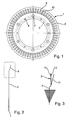
- FIG. 1 shows a sealing membrane device 1 in plan view.
- the Sealing membrane device 1 is elastic and is also used as a sealing spring device, Disc spring diaphragm or short denoted membrane.
- the Sealing membrane device 1 comprises an inner body 3, which substantially has the shape of a circular disk having a plurality of through holes 4, 5 is equipped.
- the through holes 4, 5 are used for positioning on the sealing membrane device 1 or for fastening the sealing membrane 1 on another component.
- the inner body 3 is integral with an outer body 8, which also has the shape of a circular disk.
- In the outer body 8 are uniformly distributed over the circumference a plurality formed by slots 9, 10 which are both radially inward and radially outward are limited by the outer body 8.
- the slots 9, 10 are therefore in radial Direction both outwards and inwards closed.
- the inner body 3 is shown clamped.
- the outer body 8 is shown at 11 in the unloaded state.
- the outer body 8 is in its Plane shown, in which the outer body 8 parallel to the inner body. 3 is arranged.
- the outer body 8 is shown in the installed state.
- the outer body 8 is built in or clamped state 13 from the unloaded state 11 via his flatness 12 also over.
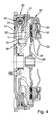
- a torsional vibration damper 20 is shown, which is a primary Flywheel 21 and a secondary flywheel 22 includes.
- the two Flywheels 21 and 22, which are also referred to as flywheels, are distributed over a plurality of circumferentially distributed energy storage elements 24, which are preferably formed by helical compression springs, coupled together.
- the secondary flywheel 22 is via a flange 25, which is fastened to the secondary flywheel 22 by rivet connections 26 is coupled with this.
- the sealing membrane device 1 shown in Figures 1 to 3 is with her Inner body between the flange 25 and the secondary flywheel 22nd clamped.
- the outer body of the sealing membrane device 1 lies with his Outer edge on an extension 27 of the primary flywheel 21 at.
- Of the Outer body of the sealing membrane device 1 is light when installed suppressed, so bent from the unloaded state beyond its flatness or angled.
- the secondary flywheel 22 forms the counter-pressure plate of a clutch 28, which comprises a clutch disc 29 with friction linings 30.
- the friction linings 30 are disposed between the platen 22 and a pressure plate 32, by means of a disc spring device 33 relative to a clutch cover 34 is movable in the axial direction to the friction linings 30 of the clutch disc 29 clamped between the pressure plate 32 and the counter-pressure plate 22.
- the structure and function of a clutch with integrated torsional vibration damper are assumed to be known and therefore not here further explained.
- the elastic sealing membrane device 1 shown in FIGS. 1 to 4 is preferably formed from sheet metal, which preferably has a thickness of 0.25 to 0.3 Has millimeter.
- the sealing membrane device 1, which also serves as a diaphragm spring diaphragm is designated, outside has a closed edge, the also called force margin.
- the diaphragm spring diaphragm 1 is also inside closed trained.
- the inside closed force margin causes a Stiffening of the entire component, so that the sealing membrane device 1 or the diaphragm spring can be placed much higher and no Snap effect occurs.
- the diaphragm spring or sealing membrane device does not need any additional support, as with disc springs with tongues.
- the scattering of the spring force in the spring characteristic shown in Figure 5 is between 70 Newton and 90 Newton and may be due a change in the installation height can be adjusted.
- FIG. 7 shows an enlarged detail from FIG. 6 according to a first embodiment shown. As seen in Figure 7, is on the clutch cover 34, a step 41 is formed, which serves the clutch cover 34 in the Pre-center mounting on the secondary flywheel 22.
- an elevation or protuberance 44 is formed, which in a Groove 43 engages, which is formed in the secondary flywheel 22.
- the secondary flywheel 22 is preferably a Casting, in which the recess 43 generates by means of a drilling tool has been.
- the elevation 44 and the recess 43 allow positioning the clutch cover 34 relative to the secondary flywheel 22, so that the mounting holes in the two components concentric to each other to be ordered.
- Figure 9 is a similar section as in Figure 7 according to another embodiment shown.
- the engaging increase 44 in the clutch cover 34 has also a slightly changed shape.
- the term increase in use with the clutch cover 34 refers in connection with the present invention on the inner peripheral surface of the clutch cover.
- the elevation 44 protrudes from the inner peripheral surface of the clutch cover 34 in the radial direction inwards.
- FIG the secondary flywheel 22 a Verschraubungsloch 46 in, based on the Torsional vibration damper, axial direction.
- FIG. 11 is in the Verschraubungsloch 46 in the secondary flywheel 22 a screw shank 47 is screwed, the enlarged screw head 48 has.
- the screw head 48 is located radially outward on the clutch cover 34, which has a through hole 49 whose diameter is larger than that of the screw hole 46.
- the clutch cover 34 is installed in State between the secondary flywheel 22 and the screw head 48 clamped. Although only one screw connection is shown in FIGS. 10 and 11 illustrated, in practice, the clutch cover 34, however, with a Variety of such screw, preferably in the circumferential direction are arranged evenly distributed, attached to the secondary flywheel 22.
- FIG. 12 shows an enlarged detail of FIG. 6.
- a screw shank 47 is screwed in, which is an enlarged screw head 48, which bears against the clutch cover 34.
- an annular space is formed, in which a threaded pin 51 protrudes, on the secondary Flywheel 22 is formed.
- the threaded pin 51 serves to the clutch cover 34 during assembly with respect to the mounting holes to position.
- FIG. 15 shows a coupling 28 with integrated torsional vibration damper 20 shown according to another embodiment.
- the illustrated in Figure 15 Embodiment is similar to the embodiment shown in Figure 6. To repetitions to avoid is based on the previous description of the figure 6 referenced. To designate the same parts, the same reference numerals used. The following will only focus on the differences between the two Embodiments received.
- the clutch disk 29 is the equipped with an additional damping device 55.
- Secondary flywheel 22 formed as a stamped part of sheet metal, and not as a casting as in the embodiment shown in Figure 6.
- FIGS. 17 and 18 show a detail of FIG. 15 in different views shown during pre-centering. As you can see in Figure 17, it is on the nose 58, a pre-centering bevel 60 is formed, at which during assembly the notch 59 of the clutch cover 34 comes to rest. This will make the clutch cover 34 precentered relative to the secondary flywheel 22.
- FIGS. 19 and 20 show the same views as in FIGS. 17 and 18 shown during positioning.
- the clutch cover 34 When positioning comes the clutch cover 34 in the region of the notch 59 on the nose 58 of the secondary flywheel 22 to the plant. Thereby, the clutch cover 34 is relative to the flywheel 22 positioned.
- FIGS. 21 and 22 show the same views as in FIGS. 17 to 20 shown in the positioned state. As can be seen in FIGS. 21 and 22 sees, is the clutch cover 34 with its outer edge in Appendix at the secondary flywheel 22. In Figs. 17 to 22, only one is respectively a nose and a notch are shown, but there may be several noses and Notches about the circumference of the secondary flywheel 22 and the clutch disc 34 distributed.
- FIG 23 a detail of Figure 15 is shown enlarged, in which shown is like the clutch cover 34 by means of a screw 64 on the secondary Flywheel 22 is attached.
- a screw 64 on the secondary Flywheel 22 is attached.
- more Screw 64 is used, which is uniform over the circumference of the secondary Flywheel 22 distributed to be screwed.
- FIG. 24 shows a section along the line XXIV-XXIV in FIG. 23, but only the flywheel 22 without coupling shows.
- the clutch will via the notch 59 on the clutch cover 34 and the Positionieran Weggung 58 centered on the secondary flywheel 22.
- the position of the screw hole pattern on the circumference can be through a pair of notches or through Threaded pin can be ensured. Due to the centering and positioning method can be used conventionally three pins omitted.
- the secondary flywheel 22 is tool dropping made of sheet metal.
Landscapes
- Engineering & Computer Science (AREA)
- General Engineering & Computer Science (AREA)
- Mechanical Engineering (AREA)
- Physics & Mathematics (AREA)
- Acoustics & Sound (AREA)
- Aviation & Aerospace Engineering (AREA)
- Manufacturing & Machinery (AREA)
- Mechanical Operated Clutches (AREA)
- Steering Controls (AREA)
- Buildings Adapted To Withstand Abnormal External Influences (AREA)
- Surgical Instruments (AREA)
- Pulleys (AREA)
Abstract
Description
Der Innenkörper ist vorzugsweise einstückig mit dem Außenkörper.
Die Abschrägung dient zum Vorzentrieren der Kupplungsscheibe bei der Montage.
Es zeigen:
- Figur 1
- eine Dichtmembraneinrichtung in der Draufsicht;
- Figur 2
- die Dichtmembraneinrichtung aus Figur 1 im Schnitt;
- Figur 3
- einen Ausschnitt aus Figur 2 im belasteten und im unbelasteten Zustand;
- Figur 4
- eine Kupplung mit einem integrierten Drehschwingungsdämpfer und einer Dichtmembraneinrichtung, wie sie in den Figuren 1 bis 3 dargestellt ist;
- Figur 5
- die Federkennlinie der Dichtmembraneinrichtung aus den Figuren 1 bis 3;
- Figur 6
- eine Kupplung mit einem integrierten Drehschwingungsdämpfer gemäß einer weiteren Ausführungsform der Erfindung;
- Figur 7
- eine vergrößerte Einzelheit aus Figur 6;
- Figur 8
- die Ansicht eines Schnitts entlang der Linie VIII - VIII in Figur 7;
- Figur 9
- eine vergrößerte Einzelheit aus Figur 6 gemäß einer weiteren Ausführungsform;
- Figur 10
- die Ansicht eines Schnitts entlang der Linie X - X in Figur 9;
- Figur 11
- die Ansicht eines Schnitts entlang der Linie XI - XI in Figur 10;
- Figur 12
- eine vergrößerte Einzelheit aus Figur 6 mit einem vergrößerten Schraubenkopf;
- Figur 13
- eine vergrößerte Einzelheit aus Figur 6 gemäß einer weiteren Ausführungsform;
- Figur 14
- die Ansicht eines Schnitts entlang der Linie XIV - XIV in Figur 13;
- Figur 15
- eine Kupplung mit einem integrierten Drehschwingungsdämpfer gemäß einer weiteren Ausführungsform;
- Figur 16
- eine Ansicht in Richtung des Pfeils XVI in Figur 15;
- Figur 17
- die Ansicht eines Schnitts entlang der Linie XVII - XVII in Figur 16;
- Figur 18
- die Ansicht eines Schnitts entlang der Linie XVIII - XVIII in Figur 17;
- Figur 19
- die gleiche Ansicht wie in Figur 17 beim Positionieren;
- Figur 20
- die Ansicht eines Schnitts entlang der Linie XX - XX in Figur 19;
- Figur 21
- die gleiche Ansicht wie in Figur 17 im positionierten Zustand;
- Figur 23
- eine vergrößerte Einzelheit aus Figur 15 gemäß einer weiteren Ausführungsform und
- Figur 24
- die Ansicht eines Schnitts entlang der Linie XXIV - XXIV in Figur 23.
Claims (11)
- Drehschwingungsdämpfer, insbesondere geteiltes Schwungrad, mit wenigstens zwei entgegen dem Widerstand einer Energiespeichereinrichtung (24) relativ zueinander verdrehbaren Schwungmassen (22, 32), zwischen denen in einem Einbaubereich (37) eine elastische Dichtmembraneinrichtung (1) angeordnet ist, die eine Federkennlinie aufweist, die sich aus der Auftragung der Federkraft (F) und der Dichtmembraneinrichtung über dem Federweg (f) ergibt, dadurch gekennzeichnet, dass die Federkennlinie der Dichtmembraneinrichtung (1) in dem Einbaubereich (37) zunächst abfällt und dann ansteigt.
- Drehschwingungsdämpfer nach Anspruch 1, dadurch gekennzeichnet, dass die Dichtmembraneinrichtung (1) radial innen einen im Wesentlichen kreisringscheibenförmigen Innenkörper (3) aufweist, der mit der einen Schwungmasse (21) verbunden ist, und dadurch, dass die Dichtmembraneinrichtung (1) radial außen einen im Wesentlichen kreisringscheibenförmigen Außenkörper (8) aufweist, der an der anderen Schwungmasse (22) anliegt.
- Drehschwingungsdämpfer nach Anspruch 2, dadurch gekennzeichnet, dass der Außenkörper (8), im Querschnitt betrachtet, im unbelasteten Zustand relativ zu dem Innenkörper (3) in eine Richtung (11) geneigt ist, und dadurch, dass der Außenkörper (8) im eingebauten Zustand relativ zu dem Innenkörper in die entgegengesetzte Richtung (13) geneigt ist.
- Drehschwingungsdämpfer nach einem der vorhergehenden Ansprüche, dadurch gekennzeichnet, dass der Außenkörper (8) mit einer Vielzahl radialer Schlitze (9, 10) versehen ist, die in radialer Richtung innen und außen geschlossen ausgebildet sind.
- Drehschwingungsdämpfer nach einem der vorhergehenden Ansprüche, dadurch gekennzeichnet, dass der Innenkörper (3) mehrere Durchgangöffnungen (4, 5) aufweist und radial innen geschlossen ausgebildet ist.
- Drehschwingungsdämpfer, insbesondere geteiltes Schwungrad, mit einer primären Schwungmasse (21), die mit der Abtriebswelle einer Brennkraftmaschine koppelbar ist, und mit einer sekundären Schwungmasse (22), welche die Gegendruckplatte einer Kupplung bildet, die eine Kupplungsscheibe (29) aufweist, die zwischen der Gegendruckplatte (22) und einer Druckplatte (32) einklemmbar ist, die relativ zu einem Kupplungsdeckel (34) in axialer Richtung bewegbar und mit einer Getriebeeingangswelle koppelbar ist, dadurch gekennzeichnet, dass an dem Kupplungsdeckel (34) radial außen eine umlaufende Vorzentrierstufe (41) ausgebildet ist, die bei der Montage teilweise an der Gegendruckplatte (22) zur Anlage kommt.
- Drehschwingungsdämpfer nach Anspruch 6, insbesondere nach dem Oberbegriff von Anspruch 6, dadurch gekennzeichnet, dass an einem Umfangsrand des Kupplungsdeckels (34) radial innen mindestens eine Erhöhung (44) ausgebildet ist, die im zusammengebauten Zustand in eine Vertiefung (43) eingreift, die radial außen an der Gegendruckplatte (22) ausgebildet ist.
- Drehschwingungsdämpfer nach Anspruch 6 oder 7, insbesondere nach dem Oberbegriff von Anspruch 6, wobei an der Gegendruckplatte (22) Löcher (46) zur Aufnahme von Befestigungsmitteln (47, 48) vorgesehen sind, dadurch gekennzeichnet, dass sich mindestens eines der Löcher in einem Zapfen (49) fortsetzt, der von der Gegendruckplatte (22) in ein Durchgangsloch (51) ragt, das in dem Kupplungsdeckel (34) zur Aufnahme der Befestigungsmittel (47, 48) vorgesehen ist.
- Drehschwingungsdämpfer, insbesondere geteiltes Schwungrad, mit einer primären Schwungmasse (21), die mit der Abtriebswelle einer Brennkraftmaschine koppelbar ist, und mit einer sekundären Schwungmasse (22), welche die Gegendruckplatte einer Kupplung (28) mit einer Kupplungsscheibe (29) bildet, die zwischen der Gegendruckplatte (22) und einer Druckplatte (32) einklemmbar ist, die relativ zu einem Kupplungsdeckel (34) in axialer Richtung bewegbar und mit einer Getriebeeingangswelle koppelbar ist, dadurch gekennzeichnet, dass der Kupplungsdeckel (34) radial außen mit mindestens einer Kerbe (59) ausgestattet ist, in die im zusammengebauten Zustand eine Nase (58) eingreift, die an der sekundären Schwungscheibe (22) vorgesehen ist.
- Drehschwingungsdämpfer nach Anspruch 9, dadurch gekennzeichnet, dass die Nase (58) mit einer Abschrägung (60) versehen ist.
- Kupplung mit einer Gegendruckplatte (22) und mit einer Kupplungsscheibe (29), die zwischen der Gegendruckplatte (22) und einer Druckplatte (32) einklemmbar ist, die relativ zu einem Kupplungsdeckel (34) in axialer Richtung bewegbar und mit einer Getriebeeingangswelle koppelbar ist, gekennzeichnet durch einen Drehschwingungsdämpfer nach einem der vorhergehenden Ansprüche.
Priority Applications (1)
| Application Number | Priority Date | Filing Date | Title |
|---|---|---|---|
| EP06004972A EP1666764B1 (de) | 2003-07-28 | 2004-07-15 | Drehschwingungsdämpfer |
Applications Claiming Priority (2)
| Application Number | Priority Date | Filing Date | Title |
|---|---|---|---|
| DE10334314 | 2003-07-28 | ||
| DE10334314 | 2003-07-28 |
Related Child Applications (1)
| Application Number | Title | Priority Date | Filing Date |
|---|---|---|---|
| EP06004972A Division EP1666764B1 (de) | 2003-07-28 | 2004-07-15 | Drehschwingungsdämpfer |
Publications (3)
| Publication Number | Publication Date |
|---|---|
| EP1503104A2 true EP1503104A2 (de) | 2005-02-02 |
| EP1503104A3 EP1503104A3 (de) | 2005-02-16 |
| EP1503104B1 EP1503104B1 (de) | 2006-11-29 |
Family
ID=33521432
Family Applications (2)
| Application Number | Title | Priority Date | Filing Date |
|---|---|---|---|
| EP04016646A Expired - Lifetime EP1503104B1 (de) | 2003-07-28 | 2004-07-15 | Drehschwingungsdämpfer |
| EP06004972A Expired - Lifetime EP1666764B1 (de) | 2003-07-28 | 2004-07-15 | Drehschwingungsdämpfer |
Family Applications After (1)
| Application Number | Title | Priority Date | Filing Date |
|---|---|---|---|
| EP06004972A Expired - Lifetime EP1666764B1 (de) | 2003-07-28 | 2004-07-15 | Drehschwingungsdämpfer |
Country Status (6)
| Country | Link |
|---|---|
| EP (2) | EP1503104B1 (de) |
| KR (2) | KR101181956B1 (de) |
| CN (1) | CN100419292C (de) |
| AT (2) | ATE532987T1 (de) |
| BR (1) | BRPI0402781B1 (de) |
| DE (2) | DE102004034087A1 (de) |
Cited By (4)
| Publication number | Priority date | Publication date | Assignee | Title |
|---|---|---|---|---|
| WO2007006254A3 (de) * | 2005-07-14 | 2007-04-26 | Luk Lamellen & Kupplungsbau | Schwingungsdämpfungseinrichtung, insbesondere zweimassenschwungrad |
| WO2015127932A1 (de) * | 2014-02-26 | 2015-09-03 | Schaeffler Technologies AG & Co. KG | Gegendruckplatte für eine kupplung |
| WO2018065005A1 (de) * | 2016-10-07 | 2018-04-12 | Schaeffler Technologies AG & Co. KG | Unterzusammenbau für ein zweimassenschwungrad, wuchtanlage und verfahren zum wuchten eines unterzusammenbaus |
| US20220032686A1 (en) * | 2020-10-16 | 2022-02-03 | Sram Deutschland Gmbh | Bicycle wheel hub |
Families Citing this family (15)
| Publication number | Priority date | Publication date | Assignee | Title |
|---|---|---|---|---|
| CN101223380B (zh) * | 2005-07-14 | 2012-01-11 | 舍弗勒技术两合公司 | 减振装置、尤其是双质量飞轮 |
| ATE547566T1 (de) † | 2007-04-23 | 2012-03-15 | Wirtgen Gmbh | SELBSTFAHRENDE STRAßENBAUMASCHINE |
| DE102008043663B4 (de) | 2008-11-12 | 2022-01-27 | Zf Friedrichshafen Ag | Torsionsschwingungsdämpfer, insbesondere für den Antriebsstrang eines Fahrzeugs |
| DE102008054560A1 (de) | 2008-12-12 | 2010-06-17 | Zf Friedrichshafen Ag | Drehmomentübertragungseinheit, insbesondere für den Antriebsstrang eines Fahrzeugs |
| WO2010127653A1 (de) * | 2009-04-27 | 2010-11-11 | Schaeffler Technologies Gmbh & Co. Kg | Schwingungsdämpfer |
| US20130205944A1 (en) * | 2010-05-07 | 2013-08-15 | Zf Friedrichshafen Ag | Torque Transmission Assembly, In Particular Hydrodynamic Torque Converter, Fluid Coupling Or Wet-Running Clutch |
| WO2012010114A2 (de) * | 2010-06-29 | 2012-01-26 | Schaeffler Technologies Gmbh & Co. Kg | Kupplungsaggregat und verfahren zur montage eines kupplungsaggregats |
| ITTO20120263A1 (it) * | 2012-03-22 | 2013-09-23 | Dayco Europe Srl | Volano a doppia massa e molla a spirale con configurazione in parallelo |
| JP5734365B2 (ja) | 2013-06-04 | 2015-06-17 | 株式会社エクセディ | トルクコンバータのロックアップ装置 |
| JP5685304B2 (ja) | 2013-06-04 | 2015-03-18 | 株式会社エクセディ | トルクコンバータのロックアップ装置 |
| JP5878893B2 (ja) | 2013-07-11 | 2016-03-08 | 株式会社エクセディ | トルクコンバータのロックアップ装置 |
| DE102015225239A1 (de) | 2015-12-15 | 2017-06-22 | Schaeffler Technologies AG & Co. KG | Drehschwingungsdämpfer |
| CN106481731B (zh) * | 2016-09-29 | 2019-11-19 | 珠海华粤传动科技有限公司 | 一种圆弧弹簧减震器 |
| DE102019110681B4 (de) * | 2019-04-25 | 2025-09-25 | Schaeffler Technologies AG & Co. KG | Drehmomentübertragungseinrichtung, Hybridischer Antriebsstrang mit dieser und Elektromaschine für diesen |
| CN116379107B (zh) * | 2023-04-07 | 2025-09-19 | 华东交通大学 | 一种弯扭复合减振器 |
Family Cites Families (12)
| Publication number | Priority date | Publication date | Assignee | Title |
|---|---|---|---|---|
| DE8509183U1 (de) | 1985-03-27 | 1985-07-04 | Fichtel & Sachs Ag, 8720 Schweinfurt | Kupplungsgehäusebefestigung über Sprengring |
| GB2217429B (en) * | 1988-03-26 | 1991-12-18 | Luk Lamellen & Kupplungsbau | Apparatus for damping vibrations |
| US5146811A (en) * | 1990-12-24 | 1992-09-15 | Luk Lamellen Und Kupplungsbau Gmbh | Vibration damping apparatus |
| DE4311102C2 (de) | 1993-04-03 | 2002-06-20 | Zf Sachs Ag | Schwungrad mit reduziertem Außendurchmesser |
| FR2715204B1 (fr) | 1994-01-18 | 1996-03-01 | Valeo | Double volant amortisseur, notamment pour véhicule automobile. |
| JP3805803B2 (ja) * | 1994-02-08 | 2006-08-09 | 株式会社エクセディ | 動力伝達装置 |
| FR2786240B1 (fr) * | 1998-11-19 | 2001-02-09 | Valeo | Amortisseur de torsion, notamment double volant amortisseur, pour vehicule automobile |
| DE10002259B4 (de) * | 1999-01-25 | 2019-03-28 | Schaeffler Technologies AG & Co. KG | Drehmomentübertragungseinrichtung |
| JP2001020973A (ja) | 1999-07-08 | 2001-01-23 | Exedy Corp | ツインダンパーディスク組立体及びそれを使用したツインクラッチ |
| FR2801356B1 (fr) * | 1999-11-23 | 2002-02-08 | Valeo | Dispositif a volant d'inertie, en particulier pour embrayage |
| DE10004125A1 (de) * | 2000-01-31 | 2001-08-02 | Mannesmann Sachs Ag | Torsionsschwingungsdämpfer |
| JP5076205B2 (ja) | 2001-01-19 | 2012-11-21 | シェフラー テクノロジーズ アクチエンゲゼルシャフト ウント コンパニー コマンディートゲゼルシャフト | ねじり振動減衰器 |
-
2004
- 2004-07-15 EP EP04016646A patent/EP1503104B1/de not_active Expired - Lifetime
- 2004-07-15 DE DE102004034087A patent/DE102004034087A1/de not_active Withdrawn
- 2004-07-15 DE DE502004002148T patent/DE502004002148D1/de not_active Expired - Lifetime
- 2004-07-15 AT AT06004972T patent/ATE532987T1/de active
- 2004-07-15 AT AT04016646T patent/ATE347059T1/de not_active IP Right Cessation
- 2004-07-15 EP EP06004972A patent/EP1666764B1/de not_active Expired - Lifetime
- 2004-07-16 BR BRPI0402781A patent/BRPI0402781B1/pt not_active IP Right Cessation
- 2004-07-21 KR KR1020040056709A patent/KR101181956B1/ko not_active Expired - Fee Related
- 2004-07-28 CN CNB2004100587055A patent/CN100419292C/zh not_active Expired - Fee Related
-
2011
- 2011-07-22 KR KR1020110073012A patent/KR101230805B1/ko not_active Expired - Fee Related
Cited By (4)
| Publication number | Priority date | Publication date | Assignee | Title |
|---|---|---|---|---|
| WO2007006254A3 (de) * | 2005-07-14 | 2007-04-26 | Luk Lamellen & Kupplungsbau | Schwingungsdämpfungseinrichtung, insbesondere zweimassenschwungrad |
| WO2015127932A1 (de) * | 2014-02-26 | 2015-09-03 | Schaeffler Technologies AG & Co. KG | Gegendruckplatte für eine kupplung |
| WO2018065005A1 (de) * | 2016-10-07 | 2018-04-12 | Schaeffler Technologies AG & Co. KG | Unterzusammenbau für ein zweimassenschwungrad, wuchtanlage und verfahren zum wuchten eines unterzusammenbaus |
| US20220032686A1 (en) * | 2020-10-16 | 2022-02-03 | Sram Deutschland Gmbh | Bicycle wheel hub |
Also Published As
| Publication number | Publication date |
|---|---|
| EP1503104B1 (de) | 2006-11-29 |
| EP1666764A3 (de) | 2006-09-06 |
| EP1503104A3 (de) | 2005-02-16 |
| ATE532987T1 (de) | 2011-11-15 |
| KR101230805B1 (ko) | 2013-02-06 |
| DE502004002148D1 (de) | 2007-01-11 |
| CN1576627A (zh) | 2005-02-09 |
| KR20050013494A (ko) | 2005-02-04 |
| CN100419292C (zh) | 2008-09-17 |
| KR101181956B1 (ko) | 2012-09-12 |
| EP1666764B1 (de) | 2011-11-09 |
| DE102004034087A1 (de) | 2005-02-17 |
| KR20110091493A (ko) | 2011-08-11 |
| BRPI0402781B1 (pt) | 2016-05-24 |
| BRPI0402781A (pt) | 2005-06-07 |
| EP1666764A2 (de) | 2006-06-07 |
| ATE347059T1 (de) | 2006-12-15 |
Similar Documents
| Publication | Publication Date | Title |
|---|---|---|
| EP1503104A2 (de) | Drehschwingungsdämpfer | |
| DE69634788T2 (de) | Dämpfungsscheibeneinheit mit einem Reibungsmechanismus mit verbesserten Reibungselementen | |
| DE4345641B4 (de) | Drehmomentübertragungseinrichtung | |
| DE112007002295B4 (de) | Dämpfungsmechanismus | |
| DE4339421B4 (de) | Zwei-Massen-Schwungrad | |
| DE4117584A1 (de) | Geteiltes schwungrad | |
| DE10206742A1 (de) | Vibrationsdämpfungsvorrichtung | |
| DE2018310A1 (de) | Drehschwmgungsdämpfer | |
| EP1841983B1 (de) | Dämpfungseinrichtung, insbesondere für ein zweimassenschwungrad | |
| DE4420927A1 (de) | Drehmomentübertragungseinrichtung | |
| EP1462675B1 (de) | Drehschwingungsdämpfer | |
| EP2672139A2 (de) | Torsionsschwingungsdämpferanordnung, insbesondere in einer Kupplungsscheibe | |
| EP2229541B1 (de) | Drehmomentübertragungsvorrichtung eines kraftfahrzeugs | |
| DE4212190A1 (de) | Elastische lagerung mit einer fluidfuellung | |
| DE102011087066A1 (de) | Selbstnachstellende Kupplung | |
| EP1503103B1 (de) | Drehschwingungsdämpfer | |
| WO2017076407A1 (de) | Fliehkraftpendeleinrichtung, drehmomentübertragungseinrichtung und verfahren zum montieren und auswuchten einer fliehkraftpendeleinrichtung | |
| DE69503721T3 (de) | Drehschwingungsdämpfer, insbesondere für Kraftfahrzeuge | |
| DE19514817A1 (de) | Reibungskupplung für ein Kraftfahrzeug | |
| DE19982216B4 (de) | Zweimassen-Dämpfungsschwungrad, insbesondere für Kraftfahrzeuge | |
| DE102004016960A1 (de) | Schwungradanordnung | |
| DE19949362A1 (de) | Torsionsschwingungsdämpfer | |
| DE10340095A1 (de) | Torsionsschwingungsdämpfer mit einer Reibvorrichtung | |
| DE4424986C2 (de) | Torsionsschwingungsdämpfer für die Überbrückungskupplung eines hydrodynamischen Drehmomentwandlers | |
| DE4417654C2 (de) | Torsionsschwingungsdämpfeinrichtung mit einem Abstandsring |
Legal Events
| Date | Code | Title | Description |
|---|---|---|---|
| PUAI | Public reference made under article 153(3) epc to a published international application that has entered the european phase |
Free format text: ORIGINAL CODE: 0009012 |
|
| PUAL | Search report despatched |
Free format text: ORIGINAL CODE: 0009013 |
|
| AK | Designated contracting states |
Kind code of ref document: A2 Designated state(s): AT BE BG CH CY CZ DE DK EE ES FI FR GB GR HU IE IT LI LU MC NL PL PT RO SE SI SK TR |
|
| AX | Request for extension of the european patent |
Extension state: AL HR LT LV MK |
|
| AK | Designated contracting states |
Kind code of ref document: A3 Designated state(s): AT BE BG CH CY CZ DE DK EE ES FI FR GB GR HU IE IT LI LU MC NL PL PT RO SE SI SK TR |
|
| AX | Request for extension of the european patent |
Extension state: AL HR LT LV MK |
|
| 17P | Request for examination filed |
Effective date: 20050816 |
|
| AKX | Designation fees paid |
Designated state(s): AT BE BG CH CY CZ DE DK EE ES FI FR GB GR HU IE IT LI LU MC NL PL PT RO SE SI SK TR |
|
| GRAP | Despatch of communication of intention to grant a patent |
Free format text: ORIGINAL CODE: EPIDOSNIGR1 |
|
| GRAS | Grant fee paid |
Free format text: ORIGINAL CODE: EPIDOSNIGR3 |
|
| GRAA | (expected) grant |
Free format text: ORIGINAL CODE: 0009210 |
|
| AK | Designated contracting states |
Kind code of ref document: B1 Designated state(s): AT BE BG CH CY CZ DE DK EE ES FI FR GB GR HU IE IT LI LU MC NL PL PT RO SE SI SK TR |
|
| PG25 | Lapsed in a contracting state [announced via postgrant information from national office to epo] |
Ref country code: SI Free format text: LAPSE BECAUSE OF FAILURE TO SUBMIT A TRANSLATION OF THE DESCRIPTION OR TO PAY THE FEE WITHIN THE PRESCRIBED TIME-LIMIT Effective date: 20061129 Ref country code: FI Free format text: LAPSE BECAUSE OF FAILURE TO SUBMIT A TRANSLATION OF THE DESCRIPTION OR TO PAY THE FEE WITHIN THE PRESCRIBED TIME-LIMIT Effective date: 20061129 Ref country code: NL Free format text: LAPSE BECAUSE OF FAILURE TO SUBMIT A TRANSLATION OF THE DESCRIPTION OR TO PAY THE FEE WITHIN THE PRESCRIBED TIME-LIMIT Effective date: 20061129 Ref country code: IE Free format text: LAPSE BECAUSE OF FAILURE TO SUBMIT A TRANSLATION OF THE DESCRIPTION OR TO PAY THE FEE WITHIN THE PRESCRIBED TIME-LIMIT Effective date: 20061129 Ref country code: RO Free format text: LAPSE BECAUSE OF FAILURE TO SUBMIT A TRANSLATION OF THE DESCRIPTION OR TO PAY THE FEE WITHIN THE PRESCRIBED TIME-LIMIT Effective date: 20061129 Ref country code: PL Free format text: LAPSE BECAUSE OF FAILURE TO SUBMIT A TRANSLATION OF THE DESCRIPTION OR TO PAY THE FEE WITHIN THE PRESCRIBED TIME-LIMIT Effective date: 20061129 Ref country code: CZ Free format text: LAPSE BECAUSE OF FAILURE TO SUBMIT A TRANSLATION OF THE DESCRIPTION OR TO PAY THE FEE WITHIN THE PRESCRIBED TIME-LIMIT Effective date: 20061129 Ref country code: SK Free format text: LAPSE BECAUSE OF FAILURE TO SUBMIT A TRANSLATION OF THE DESCRIPTION OR TO PAY THE FEE WITHIN THE PRESCRIBED TIME-LIMIT Effective date: 20061129 |
|
| REG | Reference to a national code |
Ref country code: GB Ref legal event code: FG4D Free format text: NOT ENGLISH |
|
| REG | Reference to a national code |
Ref country code: CH Ref legal event code: EP |
|
| REG | Reference to a national code |
Ref country code: IE Ref legal event code: FG4D Free format text: LANGUAGE OF EP DOCUMENT: GERMAN |
|
| REF | Corresponds to: |
Ref document number: 502004002148 Country of ref document: DE Date of ref document: 20070111 Kind code of ref document: P |
|
| PG25 | Lapsed in a contracting state [announced via postgrant information from national office to epo] |
Ref country code: BG Free format text: LAPSE BECAUSE OF FAILURE TO SUBMIT A TRANSLATION OF THE DESCRIPTION OR TO PAY THE FEE WITHIN THE PRESCRIBED TIME-LIMIT Effective date: 20070228 Ref country code: DK Free format text: LAPSE BECAUSE OF FAILURE TO SUBMIT A TRANSLATION OF THE DESCRIPTION OR TO PAY THE FEE WITHIN THE PRESCRIBED TIME-LIMIT Effective date: 20070228 Ref country code: SE Free format text: LAPSE BECAUSE OF FAILURE TO SUBMIT A TRANSLATION OF THE DESCRIPTION OR TO PAY THE FEE WITHIN THE PRESCRIBED TIME-LIMIT Effective date: 20070228 |
|
| PG25 | Lapsed in a contracting state [announced via postgrant information from national office to epo] |
Ref country code: ES Free format text: LAPSE BECAUSE OF FAILURE TO SUBMIT A TRANSLATION OF THE DESCRIPTION OR TO PAY THE FEE WITHIN THE PRESCRIBED TIME-LIMIT Effective date: 20070312 |
|
| PG25 | Lapsed in a contracting state [announced via postgrant information from national office to epo] |
Ref country code: PT Free format text: LAPSE BECAUSE OF FAILURE TO SUBMIT A TRANSLATION OF THE DESCRIPTION OR TO PAY THE FEE WITHIN THE PRESCRIBED TIME-LIMIT Effective date: 20070430 |
|
| ET | Fr: translation filed | ||
| NLV1 | Nl: lapsed or annulled due to failure to fulfill the requirements of art. 29p and 29m of the patents act | ||
| GBV | Gb: ep patent (uk) treated as always having been void in accordance with gb section 77(7)/1977 [no translation filed] |
Effective date: 20061129 |
|
| REG | Reference to a national code |
Ref country code: IE Ref legal event code: FD4D |
|
| PLBE | No opposition filed within time limit |
Free format text: ORIGINAL CODE: 0009261 |
|
| STAA | Information on the status of an ep patent application or granted ep patent |
Free format text: STATUS: NO OPPOSITION FILED WITHIN TIME LIMIT |
|
| 26N | No opposition filed |
Effective date: 20070830 |
|
| PG25 | Lapsed in a contracting state [announced via postgrant information from national office to epo] |
Ref country code: GB Free format text: LAPSE BECAUSE OF FAILURE TO SUBMIT A TRANSLATION OF THE DESCRIPTION OR TO PAY THE FEE WITHIN THE PRESCRIBED TIME-LIMIT Effective date: 20061129 |
|
| BERE | Be: lapsed |
Owner name: LUK LAMELLEN UND KUPPLUNGSBAU BETEILIGUNGS K.G. Effective date: 20070731 |
|
| PG25 | Lapsed in a contracting state [announced via postgrant information from national office to epo] |
Ref country code: GR Free format text: LAPSE BECAUSE OF FAILURE TO SUBMIT A TRANSLATION OF THE DESCRIPTION OR TO PAY THE FEE WITHIN THE PRESCRIBED TIME-LIMIT Effective date: 20070301 Ref country code: MC Free format text: LAPSE BECAUSE OF NON-PAYMENT OF DUE FEES Effective date: 20070731 |
|
| PG25 | Lapsed in a contracting state [announced via postgrant information from national office to epo] |
Ref country code: BE Free format text: LAPSE BECAUSE OF NON-PAYMENT OF DUE FEES Effective date: 20070731 |
|
| PG25 | Lapsed in a contracting state [announced via postgrant information from national office to epo] |
Ref country code: AT Free format text: LAPSE BECAUSE OF NON-PAYMENT OF DUE FEES Effective date: 20070715 |
|
| PGFP | Annual fee paid to national office [announced via postgrant information from national office to epo] |
Ref country code: IT Payment date: 20080721 Year of fee payment: 5 |
|
| PG25 | Lapsed in a contracting state [announced via postgrant information from national office to epo] |
Ref country code: EE Free format text: LAPSE BECAUSE OF FAILURE TO SUBMIT A TRANSLATION OF THE DESCRIPTION OR TO PAY THE FEE WITHIN THE PRESCRIBED TIME-LIMIT Effective date: 20061129 |
|
| REG | Reference to a national code |
Ref country code: CH Ref legal event code: PL |
|
| PG25 | Lapsed in a contracting state [announced via postgrant information from national office to epo] |
Ref country code: CH Free format text: LAPSE BECAUSE OF NON-PAYMENT OF DUE FEES Effective date: 20080731 Ref country code: LI Free format text: LAPSE BECAUSE OF NON-PAYMENT OF DUE FEES Effective date: 20080731 |
|
| PG25 | Lapsed in a contracting state [announced via postgrant information from national office to epo] |
Ref country code: LU Free format text: LAPSE BECAUSE OF NON-PAYMENT OF DUE FEES Effective date: 20070715 Ref country code: CY Free format text: LAPSE BECAUSE OF FAILURE TO SUBMIT A TRANSLATION OF THE DESCRIPTION OR TO PAY THE FEE WITHIN THE PRESCRIBED TIME-LIMIT Effective date: 20061129 |
|
| PG25 | Lapsed in a contracting state [announced via postgrant information from national office to epo] |
Ref country code: HU Free format text: LAPSE BECAUSE OF FAILURE TO SUBMIT A TRANSLATION OF THE DESCRIPTION OR TO PAY THE FEE WITHIN THE PRESCRIBED TIME-LIMIT Effective date: 20070530 Ref country code: TR Free format text: LAPSE BECAUSE OF FAILURE TO SUBMIT A TRANSLATION OF THE DESCRIPTION OR TO PAY THE FEE WITHIN THE PRESCRIBED TIME-LIMIT Effective date: 20061129 |
|
| PG25 | Lapsed in a contracting state [announced via postgrant information from national office to epo] |
Ref country code: IT Free format text: LAPSE BECAUSE OF NON-PAYMENT OF DUE FEES Effective date: 20090715 |
|
| REG | Reference to a national code |
Ref country code: DE Ref legal event code: R081 Ref document number: 502004002148 Country of ref document: DE Owner name: SCHAEFFLER TECHNOLOGIES AG & CO. KG, DE Free format text: FORMER OWNER: SCHAEFFLER TECHNOLOGIES GMBH & CO. KG, 91074 HERZOGENAURACH, DE Effective date: 20120828 Ref country code: DE Ref legal event code: R081 Ref document number: 502004002148 Country of ref document: DE Owner name: SCHAEFFLER TECHNOLOGIES GMBH & CO. KG, DE Free format text: FORMER OWNER: SCHAEFFLER TECHNOLOGIES GMBH & CO. KG, 91074 HERZOGENAURACH, DE Effective date: 20120828 |
|
| REG | Reference to a national code |
Ref country code: FR Ref legal event code: TP Owner name: SCHAEFFLER TECHNOLOGIES AG & CO. KG, DE Effective date: 20130408 |
|
| REG | Reference to a national code |
Ref country code: DE Ref legal event code: R081 Ref document number: 502004002148 Country of ref document: DE Owner name: SCHAEFFLER TECHNOLOGIES GMBH & CO. KG, DE Free format text: FORMER OWNER: SCHAEFFLER TECHNOLOGIES AG & CO. KG, 91074 HERZOGENAURACH, DE Effective date: 20140213 Ref country code: DE Ref legal event code: R081 Ref document number: 502004002148 Country of ref document: DE Owner name: SCHAEFFLER TECHNOLOGIES AG & CO. KG, DE Free format text: FORMER OWNER: SCHAEFFLER TECHNOLOGIES AG & CO. KG, 91074 HERZOGENAURACH, DE Effective date: 20140213 |
|
| REG | Reference to a national code |
Ref country code: DE Ref legal event code: R081 Ref document number: 502004002148 Country of ref document: DE Owner name: SCHAEFFLER TECHNOLOGIES AG & CO. KG, DE Free format text: FORMER OWNER: SCHAEFFLER TECHNOLOGIES GMBH & CO. KG, 91074 HERZOGENAURACH, DE Effective date: 20150126 |
|
| REG | Reference to a national code |
Ref country code: FR Ref legal event code: PLFP Year of fee payment: 13 |
|
| REG | Reference to a national code |
Ref country code: FR Ref legal event code: PLFP Year of fee payment: 14 |
|
| REG | Reference to a national code |
Ref country code: FR Ref legal event code: PLFP Year of fee payment: 15 |
|
| PGFP | Annual fee paid to national office [announced via postgrant information from national office to epo] |
Ref country code: DE Payment date: 20220920 Year of fee payment: 19 |
|
| PGFP | Annual fee paid to national office [announced via postgrant information from national office to epo] |
Ref country code: FR Payment date: 20220720 Year of fee payment: 19 |
|
| P01 | Opt-out of the competence of the unified patent court (upc) registered |
Effective date: 20230523 |
|
| REG | Reference to a national code |
Ref country code: DE Ref legal event code: R119 Ref document number: 502004002148 Country of ref document: DE |
|
| PG25 | Lapsed in a contracting state [announced via postgrant information from national office to epo] |
Ref country code: DE Free format text: LAPSE BECAUSE OF NON-PAYMENT OF DUE FEES Effective date: 20240201 |
|
| PG25 | Lapsed in a contracting state [announced via postgrant information from national office to epo] |
Ref country code: FR Free format text: LAPSE BECAUSE OF NON-PAYMENT OF DUE FEES Effective date: 20230731 |