EP1499250B1 - Kompakte kieferknochen-distraktionsvorrichtung - Google Patents
Kompakte kieferknochen-distraktionsvorrichtung Download PDFInfo
- Publication number
- EP1499250B1 EP1499250B1 EP03728593A EP03728593A EP1499250B1 EP 1499250 B1 EP1499250 B1 EP 1499250B1 EP 03728593 A EP03728593 A EP 03728593A EP 03728593 A EP03728593 A EP 03728593A EP 1499250 B1 EP1499250 B1 EP 1499250B1
- Authority
- EP
- European Patent Office
- Prior art keywords
- footplate
- actuator
- bone
- outer sleeve
- screw
- Prior art date
- Legal status (The legal status is an assumption and is not a legal conclusion. Google has not performed a legal analysis and makes no representation as to the accuracy of the status listed.)
- Expired - Lifetime
Links
- 210000002050 maxilla Anatomy 0.000 claims abstract description 43
- 230000000399 orthopedic effect Effects 0.000 claims abstract description 39
- 210000000216 zygoma Anatomy 0.000 claims abstract description 31
- 210000000988 bone and bone Anatomy 0.000 claims description 106
- 239000000463 material Substances 0.000 claims description 17
- 230000033001 locomotion Effects 0.000 claims description 16
- 210000003484 anatomy Anatomy 0.000 claims description 4
- 238000007493 shaping process Methods 0.000 claims description 3
- 238000011065 in-situ storage Methods 0.000 claims description 2
- 238000000034 method Methods 0.000 abstract description 18
- 230000008878 coupling Effects 0.000 abstract description 4
- 238000010168 coupling process Methods 0.000 abstract description 4
- 238000005859 coupling reaction Methods 0.000 abstract description 4
- 230000004913 activation Effects 0.000 abstract description 2
- 230000004048 modification Effects 0.000 abstract 2
- 238000012986 modification Methods 0.000 abstract 2
- 210000000214 mouth Anatomy 0.000 description 10
- 238000001356 surgical procedure Methods 0.000 description 8
- 238000009434 installation Methods 0.000 description 6
- 238000000926 separation method Methods 0.000 description 6
- 210000004872 soft tissue Anatomy 0.000 description 6
- 238000007596 consolidation process Methods 0.000 description 5
- 230000003993 interaction Effects 0.000 description 5
- 230000008439 repair process Effects 0.000 description 5
- 230000008901 benefit Effects 0.000 description 4
- 230000008859 change Effects 0.000 description 4
- 238000003780 insertion Methods 0.000 description 4
- 230000037431 insertion Effects 0.000 description 4
- 230000009467 reduction Effects 0.000 description 4
- 210000001519 tissue Anatomy 0.000 description 4
- 206010009260 Cleft lip and palate Diseases 0.000 description 3
- 208000032170 Congenital Abnormalities Diseases 0.000 description 3
- 208000016653 cleft lip/palate Diseases 0.000 description 3
- 230000007246 mechanism Effects 0.000 description 3
- 230000011164 ossification Effects 0.000 description 3
- 238000003825 pressing Methods 0.000 description 3
- 231100000241 scar Toxicity 0.000 description 3
- 230000000007 visual effect Effects 0.000 description 3
- 206010009269 Cleft palate Diseases 0.000 description 2
- RTAQQCXQSZGOHL-UHFFFAOYSA-N Titanium Chemical compound [Ti] RTAQQCXQSZGOHL-UHFFFAOYSA-N 0.000 description 2
- NIXOWILDQLNWCW-UHFFFAOYSA-N acrylic acid group Chemical group C(C=C)(=O)O NIXOWILDQLNWCW-UHFFFAOYSA-N 0.000 description 2
- 238000000429 assembly Methods 0.000 description 2
- 230000000712 assembly Effects 0.000 description 2
- 238000005452 bending Methods 0.000 description 2
- 239000003638 chemical reducing agent Substances 0.000 description 2
- 239000002131 composite material Substances 0.000 description 2
- 210000001847 jaw Anatomy 0.000 description 2
- 229910052751 metal Inorganic materials 0.000 description 2
- 239000002184 metal Substances 0.000 description 2
- 239000004033 plastic Substances 0.000 description 2
- 238000010079 rubber tapping Methods 0.000 description 2
- 239000010935 stainless steel Substances 0.000 description 2
- 229910001220 stainless steel Inorganic materials 0.000 description 2
- 239000010936 titanium Substances 0.000 description 2
- 229910052719 titanium Inorganic materials 0.000 description 2
- 238000013519 translation Methods 0.000 description 2
- 206010074180 Craniofacial deformity Diseases 0.000 description 1
- 206010027543 Micrognathia Diseases 0.000 description 1
- 208000006735 Periostitis Diseases 0.000 description 1
- 229910001069 Ti alloy Inorganic materials 0.000 description 1
- 239000000560 biocompatible material Substances 0.000 description 1
- 230000015572 biosynthetic process Effects 0.000 description 1
- 230000008468 bone growth Effects 0.000 description 1
- 230000001055 chewing effect Effects 0.000 description 1
- 206010009259 cleft lip Diseases 0.000 description 1
- 230000008602 contraction Effects 0.000 description 1
- 238000012937 correction Methods 0.000 description 1
- 230000001054 cortical effect Effects 0.000 description 1
- 238000002316 cosmetic surgery Methods 0.000 description 1
- 238000002788 crimping Methods 0.000 description 1
- 125000004122 cyclic group Chemical group 0.000 description 1
- 230000007812 deficiency Effects 0.000 description 1
- 238000013461 design Methods 0.000 description 1
- 238000006073 displacement reaction Methods 0.000 description 1
- 238000002224 dissection Methods 0.000 description 1
- 230000000694 effects Effects 0.000 description 1
- 238000002474 experimental method Methods 0.000 description 1
- 230000012010 growth Effects 0.000 description 1
- 125000001475 halogen functional group Chemical group 0.000 description 1
- 230000001096 hypoplastic effect Effects 0.000 description 1
- 239000007943 implant Substances 0.000 description 1
- 238000007373 indentation Methods 0.000 description 1
- 230000007774 longterm Effects 0.000 description 1
- 238000005259 measurement Methods 0.000 description 1
- 210000003460 periosteum Anatomy 0.000 description 1
- 230000008569 process Effects 0.000 description 1
- 210000003625 skull Anatomy 0.000 description 1
- 238000002791 soaking Methods 0.000 description 1
- 230000001720 vestibular Effects 0.000 description 1
- 239000011800 void material Substances 0.000 description 1
- XLYOFNOQVPJJNP-UHFFFAOYSA-N water Substances O XLYOFNOQVPJJNP-UHFFFAOYSA-N 0.000 description 1
Images


Classifications
-
- A—HUMAN NECESSITIES
- A61—MEDICAL OR VETERINARY SCIENCE; HYGIENE
- A61B—DIAGNOSIS; SURGERY; IDENTIFICATION
- A61B17/00—Surgical instruments, devices or methods, e.g. tourniquets
- A61B17/56—Surgical instruments or methods for treatment of bones or joints; Devices specially adapted therefor
- A61B17/58—Surgical instruments or methods for treatment of bones or joints; Devices specially adapted therefor for osteosynthesis, e.g. bone plates, screws, setting implements or the like
- A61B17/60—Surgical instruments or methods for treatment of bones or joints; Devices specially adapted therefor for osteosynthesis, e.g. bone plates, screws, setting implements or the like for external osteosynthesis, e.g. distractors, contractors
- A61B17/66—Alignment, compression or distraction mechanisms
- A61B17/663—Alignment, compression or distraction mechanisms for jaw bones, e.g. subcutaneous distractors with external access
-
- A—HUMAN NECESSITIES
- A61—MEDICAL OR VETERINARY SCIENCE; HYGIENE
- A61B—DIAGNOSIS; SURGERY; IDENTIFICATION
- A61B17/00—Surgical instruments, devices or methods, e.g. tourniquets
- A61B2017/00004—(bio)absorbable, (bio)resorbable, resorptive
Definitions
- the present invention relates to an orthopedic device according to the preamble of claim 1.
- bone reduction and distraction devices A variety of orthopedic devices, including bone reduction and distraction devices, are known in the art.
- Reduction and distraction devices (commonly referred to as reducers and distractors), are used to gradually adjust the relative orientation and spacing of the bone parts on opposing sides of a bone repair site.
- bone repair site refers to any bone region which is bounded on opposing sides by relatively healthy bone regions to which orthopedic devices can be secured, such as an osteotomy (cutting of a bone) or a fracture.
- Reducers and distractors typically consist of transcutaneous pins or screws secured in the bone on either side of the bone repair site together with a mechanism which allows controlled incremental adjustment of the distance between parts of the device on opposing sides of the bone repair site.
- distractors are used to perform distraction osteogenesis (the formation of bone). This procedure was perfected by the Russian orthopedic doctor, Gavriel llizarov. A typical procedure of this type involves at most an osteotomy completely separating the bone into two segments, or at least an incision of the cortical portion of the bone. Then, the bone segments on either side of the osteotomy (or the medullary or cancellous portion of the bone on either side of the incision) may be expanded. This gradual separation allows new bone to form in the osteotomy void.
- the distraction phase is followed by a consolidation phase, during which the distractor is held fixed, and the new bone growth gains strength. Following the consolidation phase, the distractor is removed from the patient.
- One area in which distraction techniques are used is in treating patients diagnosed with maxillary hypoplasia (underdevelopment of the maxilla, or upper jawbone).
- maxillary hypoplasia underdevelopment of the maxilla, or upper jawbone.
- One particular patient population with this condition is cleft-lip and - palate patients.
- the key reason for utilizing maxillary distraction to treat these patients is in the ability to successfully overcome the substantial soft tissue forces found in the maxillary region of these patients.
- Cleft-lip and -palate patients usually undergo surgery to correct their soft tissue deformities in early infancy. These procedures involve a great deal of soft tissue dissection, and leave the patient with significant scar tissue surrounding their maxillary region.
- the maxilla is very often restricted from normal growth and can be very difficult to advance using conventional orthognathic surgery (surgery relating to treatment of the malpositioning of bones of the jaw). Maxillary distraction thus allows the tensile forces of the scar tissue to be overcome, and a greater advancement distance to be achieved, with a clinically supported expectation of a lesser degree of relapse (undesired movement of maxilla back towards its original position after treatment is finished).
- An additional patient population that can take advantage of maxillary distraction is non-cleft palate patients having an A-P (Anterior-Posterior) maxillary deficiency of large magnitude.
- A-P anterior-Posterior
- orthognathic procedures involving maxillary advancements are limited in the magnitude of the advancement of the maxilla due to the elastic properties of the surrounding soft tissues.
- the larger advancements are more likely to require a bone graft to the site to ensure the long-term stability of the advancement.
- Using distraction for maxillary advancements can eliminate the magnitude limitations as well as the need for grafting for these patients.
- Another benefit of performing maxillary distraction on cleft-lip and -palate patients is the ability to treat the maxillary hypoplastic patients at a younger age than with conventional orthognathic surgery.
- Early treatment of skeletal deformities has been gaining in popularity among craniofacial surgeons as a means of minimizing the negative psychosocial impact that craniofacial deformities have on children.
- some surgeons believe that early correction of skeletal deformities can reduce the residual impact on surrounding tissues and structures, thus improving the overall result for the patient. See, for example, Steven Cohen, M.D., F.A.C.S., "Midface Distraction," Perspectives in Plastic Surgery, Vol. 11, No. 1 .
- halo-style fixators that attach to the skull and to the maxilla by way of surgical wires affixed to an intra-oral appliance.
- KLS-Martin RED Rigid External Distraction
- Such a high profile external device is unsightly, and the psychosocial effects of wearing an external device is a major concern, especially with younger patients.
- An external device is also more subject to bumps and snags than one which is completely located within a patient's body. Accordingly, there is a need in the art to provide a device that can be used intra-orally to reliably perform distraction or reduction of the maxilla.
- the known external fixators involve a large number of component parts and accordingly are complicated to install and adjust. Accordingly, there is a need in the art to provide a device that can be used to perform distraction or reduction of the maxilla that has a relatively low part count, and is simple both to install and adjust. Furthermore, there is a need for a distractor which occupies as little space as possible in the patient's mouth, even when the device is extended to its full length. In addition, there is a need to provide the installing surgeon with the flexibility to choose from multiple actuator lengths and footplate sizes, even after installation of the device has begun. Finally, there is a need to provide an intra-oral distractor whose alignment in the patient's mouth may be easily verified.
- the present invention provides an orthopedic device for separating first and second bone segments.
- the device comprises a first footplate comprising a bone attachment portion having a bone contacting surface where at least a portion of the bone contacting surface defines a first plane, and an actuator engaging portion.
- the device further comprises a second footplate comprising a bone attachment portion having a bone contacting surface, at least a portion of the bone contacting surface defining a second plane substantially non-parallel to the first plane, and an actuator attachment portion.
- the device also comprises an actuator having a longitudinal axis, an un-actuated length and an actuated length, the actuator configured and adapted to be attached to the first bone segment using the first footplate and to the second bone segment using the second footplate.
- the actuator longitudinal axis is substantially non-parallel to the second plate, and the actuated and un-actuated lengths of the actuator is substantially equal.
- the predetermined distance may be in a range from between about 1 millimeter (mm) to about 25 mm, or the predetermined distance may be in the range from between about 7 mm to about 12 mm.
- At least one footplate may be deformable to allow shaping to the surface of the respective bone segment.
- the first and second footplate bone attachment portions may each have at least one hole configured to accept at least one bone screw for attaching the respective footplate to bone.
- At least a portion of at least one footplate may be made of a bioresorbable material.
- the at least one bioresorbable footplate may be attached to its respective bone segment by at least one bioresorbable fastener.
- the first footplate may be configured and adapted to attach to a construct, the construct being mechanically coupled to the patient's teeth.
- the second footplate may be provided with a fastener to removable fix the footplate to the actuator.
- the second footplate attachment portion may comprise a bore having a shoulder and the actuator may further comprise a distal end having a threaded bore, and the second footplate actuator attachment portion may engage the actuator, and the threaded portion of the screw may be inserted through the second footplate attachment portion bore and engage the threaded bore of the actuator.
- the actuator further comprises an advancement screw having external threading, and an outer sleeve having an axial slot and a second footplate engagement portion, the second footplate being coupled to the second footplate engagement portion.
- the first footplate further comprises an actuator engaging portion having an internally threaded bore and an outer sleeve slot engaging portion, the first footplate bore interacting with the advancement screw, and the first footplate outer sleeve slot engaging portion interacting with the outer sleeve axial slot.
- the advancement screw and the outer sleeve are associated such that only relative rotational movement of the screw and sleeve about the longitudinal axis is permitted, such that rotation of the advancement screw causes translational movement of the first footplate relative to the outer sleeve along the actuator longitudinal axis.
- At least a portion of the first footplate may be configured to attach to the maxilla and at least a portion of the second footplate may be configured to attach to the zygoma.
- the actuator may have a surface configured to engage a temporary alignment member for aligning the device prior to attachment to the bone segments, and further the device may be configured to be installed intra-orally.
- the actuator may comprise a surface comprising threads configured to engage corresponding threads of the temporary alignment member.
- the actuator may have a surface that is keyed to the temporary alignment member.
- the second footplate actuator attachment portion further may be configured to be removably engageable with the actuator.
- At least one of the footplates may be made of bioresorbable material and the actuator may be made of non-bioresorbable material.
- Each first footplate maxilla engaging portion may comprise screw holes configured to accept bone screws, and the configuration of such screw holes may be different for each first footplate. At least two of the first footplate maxilla engaging portions may comprise a different shape. Each second footplate zygoma engaging portion may further comprise screw holes configured to accept bone screws, and the configuration of such screw holes may be different for each second footplate. At least two of the second footplate zygoma engaging portions may further comprise a different shape. At least one second footplate may be configured to permit the actuation assembly to be located posterior to the zygoma by a different amount compared to at least one other second footplate.
- the predetermined distance may be in the range of from about 1 mm to about 25 mm, or the predetermined distance is in a range of from about 7 mm to about 12 mm.
- Each second footplate actuator engaging portion may be configured to engage a distal end of the at least one actuation assembly, and the at least one actuation assembly further may comprise an advancement screw having external threading, and an outer sleeve having an axial slot and a second footplate engagement portion.
- the second footplate may be coupled to the second footplate engagement portion; and each first footplate may further comprise an actuator engaging portion having an internally threaded bore and an outer sleeve slot engaging portion.
- the first footplate bore may interact with the advancement screw, and the first footplate outer sleeve slot engaging portion may interact with the outer sleeve axial slot; wherein the advancement screw and the outer sleeve are associated such that only relative rotational movement of the screw and sleeve about the longitudinal axis is permitted, such that rotation of the advancement screw causes translational movement of the first footplate relative to the outer sleeve along the actuator longitudinal axis.
- the kit may further comprise a plurality of temporary alignment elements configured to be removably engageable with the orthopedic device to permit in-situ alignment of the orthopedic device.
- the orthopedic device of the present invention is discussed herein with reference to a preferred embodiment adapted to be used in a linear distraction of the maxilla from the zygoma.
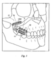
- the orthopedic system 10 generally consists of distraction assembly 11 and anchors in the form of proximal and distal bone plates 500 and 700, respectively.
- the distraction assembly 11 has a proximal, or adjustment end 12 and a distal end 13.
- the orthopedic system 10 is affixed to maxilla 21 and zygoma 22 by bone screws 14 which are inserted though screw-holes 15 in footplates 500 and 700.
- the entire orthopedic system 10 is implanted so that the distal bone plate 700 is attached to the zygoma 22 and the proximal bone plate 500 is attached to the maxilla 21, with the distraction assembly 11 nestled within the buccal sulcus.
- proximal is used to refer to the end of the device associated with the proximal end of the distraction assembly 12 that extends outwards away from the patient's zygoma 22.
- distal is used to refer to the other end of the device 13.
- the distraction assembly 11 generally consists of a lead screw 100, an inner sleeve 200, and an outer sleeve 300.
- lead screw 100 is journaled within outer sleeve 300, such that screw 100 can rotate, but not translate linearly (axially), relative to outer sleeve 300.
- Inner sleeve 200 has internal threading 202 which interacts with the external threading 104 on screw 100.
- the interaction of the inner and outer sleeves, as discussed below, is such that they can translate linearly with respect to each other, but cannot rotate relative to each other.
- Lead screw 100 has a distal shaft portion 102 provided with external screw threading 104, an enlarged-diameter intermediate portion 106, a proximal shaft portion 108, and a proximal, or adjustment end 110.
- Adjustment end 110 is provided with a tool interface 112, such as a hexagonal surface that can be driven by a standard hexagonal driving tool.
- Inner sleeve 200 is provided with internal threading 202 along at least part of its length.
- the internal threading matches the external threading 104 on screw 100.
- the inner sleeve 200 has an exterior surface 204 which is generally smooth except for longitudinal slot 206 (shown in FIG. 4 ) which extends from the proximal end 208 of the sleeve towards the distal end 210.
- the outer sleeve 300 has two different inside cavity portions.
- the proximal cavity portion 302 has an inside diameter sized so as to (rotatably) slidably accept the proximal shaft portion 108 of the screw 100.
- the distal cavity portion 304 has an inside diameter sized so as to (axially) slidably accept the inner sleeve 200.
- the external surface of the outer sleeve 306 is preferably threaded along most of its length except for the distal end 310.
- a mechanism is provided to prevent rotation but allow translation of the inner sleeve 200 in relation to the outer sleeve 300.
- this is accomplished by having a portion of the distal end of the outer sleeve 310 formed into a "key" 312 which is sized to fit the longitudinal slot 206 of inner sleeve 200.
- This can be accomplished by crimping the distal end by application of a force, by an appropriately-shaped tool, sufficient to permanently deform a portion of the distal end.
- a pin could be fixed in a though hole in the wall of the distal end, flush with the outer surface and extending radially inward, the inner end fitting in the longitudinal slot 206.
- Lead screw 100 is journaled within the outer sleeve 300, so as to allow rotation of the lead screw 100 in relation to outer sleeve 300 but preventing translational motion.
- the journaling is accomplished according to the following.
- the proximal shaft portion 108 of lead screw 100 is slidably received within the proximal cavity portion 302 of the outer sleeve 300, such that screw 100 is free to rotate relative to the outer sleeve 300.
- a collar 400 is attached to the screw on the extending region of the proximal shaft portion, for example, by inserting pin 402 through matching holes 406 and 114 in the collar and proximal shaft portion, respectively.
- the collar 400 and the enlarged-diameter intermediate shaft portion 106 "sandwich" the proximal end 308 of outer sleeve 300, thereby preventing axial translation of the screw 100 relative to outer sleeve 300. In this way, screw 100 is effectively journaled within the outer sleeve 300.
- the collar 400 also has a marking, such as an indentation, that acts as a visual reference mark 404. Since the collar rotates in conjunction with the advancement screw, the reference mark 404 gives the user of the device an easily usable visual means to measure the amount of rotation that the lead screw undergoes when it is adjusted. Knowing the thread pitch of the device, the user can easily convert angular displacement of the mark into linear advancement of the device. Other visual marking methods can be used, including the imprinting of marks on the surface of the collar.
- FIG. 5 illustrates how key 312 of the outer sleeve interacts with the longitudinal slot 206 to form a keyway. It will be appreciated that the interaction of longitudinal slot 206 and key 312 form a keyway which prevents relative rotation of the sleeves about the longitudinal axis X-X of the device (designated X-X in FIG. 3a ), while freely permitting sliding, telescoping movement of the inner sleeve 200 relative to the outer sleeve 300.
- the system provides a mechanism whereby the distractor is anchored or affixed to the patient, for example, by proximal and distal footplates 500 and 700, which are best understood by reference to FIG. 2 .
- the footplates are provided with screw holes 15 to accept the bone screws 14 (shown in FIG. 1 ) which affix the device to the bone on either side of the patient's bone repair site. These holes are preferably countersunk to reduce the height of projection of the screw heads above the footplate surface after the device is fully implanted.
- the footplates have bottom coupling surfaces 506 (shown in FIG. 6 ) and 710 (shown in FIG. 7 ) which may be flat or preferably may be shaped to conform to the contours of the bone to which it is being attached. As discussed in detail below, the coupling surfaces are bone-contacting surfaces when the footplates are attached directly to the patient's bone, or may be construct-contacting surfaces when the footplate is attached to a construct which is in turn mechanically coupled to the patient's bone
- Footplates 500 and 700 serve as the anchors, and can be made from any biocompatible material such as metal, plastic, or composites.
- the footplates may be made of titanium or titanium alloy.
- the choice of material from which to construct the footplates is a routine design matter which depends purely on the particular medical application in which the system according to this invention is used.
- the footplates are bone plates made of stainless steel. Experiments have shown that stainless steel provides the necessary strength while at the same time being malleable enough to (i) allow for adjustments to the footplates by bending them, and (ii) withstand the cyclic loading inherent in the jaw area.
- the proximal footplate 500 has a device-connecting portion 502 comprising an internally-threaded bore 504 which accepts the threading on the external surface 306 of the outer sleeve 300.
- the internally-threaded bore 504 of the proximal footplate interacts with the external surface 306 of outer sleeve 300, so that the orientation and separation of the two footplates in relation to each other can be modified as needed, by screwing the sleeve 300 into the bore 504.
- proximal footplate 500 is locked into position by tightening locking nut 600 (shown in FIG. 2 ) against it, providing sufficient frictional force to keep the footplate in place.
- the distal footplate 700 has a device-connecting portion 702 comprising a bore 704 with a diameter that will accept inner sleeve 200.
- the distal footplate is attached to the distal end of inner sleeve 210, for example, by pressing the two together, and inserting a pin 706 through holes 708 and 212.
- the proximal footplate 500 is oriented so that line P-P is generally parallel to axis X-X of the distraction assembly 11. It is also offset above and to either side of the distraction assembly 11, depending on which side of the patient the assembly is to be implanted. When placed on the right side of the patient, the footplate 500 is offset to the left of the distraction assembly 11, and vice-versa.
- FIG. 2 shows the right-side orientation of the footplate, while FIG. 6 shows the left-side orientation.
- the distal footplate 700 is oriented so that line D-D is generally orthogonal to and above axis X-X of the distraction assembly 11.
- footplates 500 and 700 has been found to provide a good combination of accessibility to the screws and holding strength when the device of the present invention is used in the distraction of the maxilla.
- the precise location of the screw holes and the contoured shape and orientation of plates 500 and 700 as seen in FIGS. 2 , 6, and 7 are not a critical aspect of the invention; other screw hole placements, plate shapes, and plate orientations could be used without departing from the scope of the present invention.
- the assembly kit for an orthopedic device is best understood by reference to FIGS. 8a through 8e .
- the lead screw 100 is first inserted into the outer sleeve 300, as shown in FIG. 8a .
- the collar 400 is then installed on the region of the proximal shaft portion 108 which extends out from the proximal end 308 of the outer sleeve 300, as shown in FIG. 8b .
- the collar 400 is captivated on the shaft by pressing pin 402 though matching holes in the collar 406 and proximal shaft portion 114.
- the distal footplate 700 is pressed onto the distal end 210 of inner sleeve 200, as shown in FIG 8c , and captivated on the shaft by pressing pin 706 through matching holes 708, 212 in the footplate and the distal shaft portion, respectively.
- the lead screw is then threaded into inner sleeve 200, as shown in FIG. 8d , care being taken that the longitudinal slot 206 on sleeve 200 is properly engaging key 312.
- Nut 600 and proximal footplate 500 are then threaded onto outer sleeve 300, as shown in FIG. 8e .
- the device of the present invention is normally used in pairs, one for each side of the patient's face.
- the surgeon makes an incision, fits the devices to the patient, temporarily removes the devices in order to perform a LeFort I osteotomy (the separation of the maxilla from the rest of the midface), attaches the devices, performs distraction and consolidation, then permanently removes the devices.
- LeFort I osteotomy the separation of the maxilla from the rest of the midface
- a maxillary vestibular incision is made on the side of the patient's mouth, so that the periosteum can be elevated to expose the maxillary and zygomatic bone.
- the assembled device is placed in the proper location and checked for the proper fit.
- the footplates are generally pre-shaped to be oriented in the proper manner, adjustments can be made to the footplates by bending them, for example, with a set of pliers.
- the distal footplate is then fastened to the zygoma with bone screws 14, using a number sufficient to provide the necessary stability and strength.
- the screws are self-tapping, so no pre-tapping of the bone is required. If needed, excess material in the footplate can be removed. For example, if not all of the screw holes need to be used, the portion of the footplate having the unused holes may be clipped off.
- the anterior footplate is then attached in the same manner. The same procedure is then repeated on the other side of the patient.
- the devices are removed, the osteotomy is performed, and the devices are put back into place.
- the incision is then closed, leaving the distraction assemblies exposed, but within the patient's mouth.
- the distraction osteogenesis procedure is performed by turning the lead screws on each device using the tool interface 112. It will be understood by reference to FIG. 1 (which does not illustrate soft tissue) that the distal end of the devices, where tool interface 112 is found, is easily accessible in the intra-oral region, between the patient's cheek and gum. Counter-clockwise rotation of the screw will result in axial lengthening of the device, resulting in a distraction force being communicated to the bones through the footplates.
- the reference mark 404 can be used to measure the changes in advancement precisely. Generally, distraction progresses at a rate of 1-2mm per day until full advancement is achieved. The advancement phase is followed by a consolidation phase, with a duration of at least twice as long as that of the advancement phase. The devices are then removed in a separate surgical procedure.
- the proximal footplates 500 of the devices are not attached to the patient's maxilla 21, but rather to a construct, such as a dental splint, which is attached to the maxilla 21.
- a typical dental splint may consist of a disk of acrylic fitted or wired to the patient's teeth.
- this alternative method of treatment is the same as that used in the normal course of treatment.
- This embodiment can be used when the maxilla 21 of the patient cannot support the bone screws 14 used to support the footplates 500. This is often the case with cleft-lip or -palate patients, who often have large voids in the maxilla 21 where bone should be present. It may also be the preferred embodiment for treating younger patients, due to the presence of un-erupted tooth buds which might be damaged by bone screws 14.
- the device footplates may be attached directly to the patient's bone. Alternatively, they may be attached to one or more constructs, which constructs are attached to the patient's bone. Indeed, the constructs do not necessarily need to be directly attached to the patient's zygoma or maxilla, but rather may be attached to the patient's teeth. What is important is that the device is mechanically coupled to the zygoma and the maxilla with sufficient rigidity in order to reliably perform the distraction. Alternately, the device may be implanted using circummaxillary wiring, in which wire is passed around the bony structure of the maxilla, to provide a firm anchorage for the device.
- FIGS. 9a and 9b shows the device as it would be implanted on the left side of a patient using this embodiment.
- the orientation of the proximal footplates 500 is mirrored from its normal orientation 30 about the horizontal plane denoted by Y-Y. That is, for the device used on the left side of the patient, the footplate 500 is positioned below and to the right of the distraction assembly 11, as seen in FIGS. 9a and 9b . In practice, this may be done by simply rotating the footplate 500 one hundred eighty degrees (180°) about the X-X axis (as described in FIG. 3a ), and switching the side of the patient's face to which the device is implanted.
- the footplate 500 used on the right side of the patient when attaching the device directly to the maxilla 21 is the same one used on the left side when attaching the device to a dental splint, and vice-versa.
- This orientation is preferred for the dental splint method because it places the footplate and screw holes closer to the horizontal plane created by the chewing surfaces of the teeth, which is the preferred position for attachment of the footplate to a dental splint.
- FIG. 9b shows a portion of the splint 3 in relation to the footplate 500.
- the footplates and/or bone screws may be made from a bioresorbable material, and are detachable from the distraction assembly. This allows easy shaping of the footplates (when heated prior to insertion, for example by soaking in hot water). After distraction and consolidation have been completed, the bioresorbable footplates are detached from the distraction assembly and the incisions are closed, leaving the footplates and bone screws in place, to eventually be absorbed into the body. This provides the advantage of not having to perform a second surgical procedure to access the screws to remove the footplates. By reducing the number of surgical procedures required, the unavoidable risk and possible complications associated with any surgery is reduced.
- the bone screws should be made of a material that takes at least as long to absorb as the material the footplates are made of, thus ensuring that the footplates are secured until absorbed fully by the body.
- Figs. 10 , 11 a and 11 b illustrate an alternative embodiment of a compact maxillary distractor in which activation of the device results in no overall change in the length "A" of the device 1000.
- the device 1000 of this embodiment generally comprises proximal and distal footplates 800, 900 connected by an actuator 1100 having a longitudinal axis "X-X.”
- the proximal footplate 800 connects to the patient's maxilla 21, while the distal footplate 900 connects to the patient's zygoma 22.
- Bone screws or other suitable fasteners may be used to fix the footplates to the respective bone segments.
- the proximal footplate 800 has a bone attachment portion 802 and an actuator engagement portion 810.
- the bone attachment portion 802 comprises at least one screw hole 804, and preferably multiple screw holes 804, suitable for the insertion of a bone screw or similar fastening device.
- the at least one screw hole 804 may be countersunk to reduce the height of projection of the screw head above the footplate surface after the device is implanted.
- the proximal footplate bone attachment portion 802 further has a bone contacting surface 806 that defines a plane "PP-PP" which is oriented substantially parallel to the patient's sagittal plane, and to the longitudinal axis "X-X" of the actuator 1100.
- the actuator engagement portion 810 comprises a threaded bore 812 configured to engage corresponding external threads 1306 of the actuator lead screw 1300.
- the bone attachment and actuator engagement portions 802, 810 are joined by an outer sleeve-engaging portion 814 which comprises a reduced thickness, or "necked,” region 816, configured to be received within a longitudinal slot 1210 in the actuator outer sleeve 1200.
- the distal footplate 900 has a bone attachment portion 902 and an actuator engagement portion 910.
- the bone attachment portion 902 comprises at least one screw hole 904, and preferably multiple screw holes 940, suitable for the insertion of a bone screw or similar fastening device.
- the at least one screw hole 904 may be countersunk to reduce the height of projection of the screw head above the footplate surface after the device is implanted.
- the distal footplate bone attachment portion 902 further has a bone contacting surface 906 that defines a plane "DP-DP" which is oriented substantially perpendicular to the patient's sagittal plane "SP-SP,” to the proximal footplate bone contacting surface plane "PP-PP" and to the longitudinal axis "X-X" of the actuator 1100.
- the distal footplate actuator engagement portion 910 comprises a bore 912 configured to engage the distal end 1206 of the actuator outer sleeve 1200.
- the actuator 1100 comprises a lead screw 1300 and an outer sleeve 1200, connected in a manner similar to that described for the actuator illustrated in Figs. 1-9 .
- the lead screw 1300 is journaled within the outer sleeve 1200 so that the screw can rotate, but not translate axially relative to the outer sleeve.
- the lead screw 1300 has proximal and distal ends 1302, 1304, and a length "SL.”
- a portion of the lead screw outer surface comprises external threads 1306 configured to engage the internally threaded bore 812 of the proximal footplate actuator attachment portion 810.
- the lead screw proximal end 1302 is unthreaded, and has a transverse hole 1308 suitable for the insertion of a pin 1310.
- An increased diameter portion 1312 is spaced a distance away from the hole 1308, such that the hole 1308 is located between the increased diameter portion 1312 and the proximal end 1302 of the lead screw 1300.
- the outer sleeve 1200 has proximal and distal ends 1204, 1206, with an internal cavity defined by outer sleeve proximal and distal end bores 1211, 1208 that may encompass the entire length "SL" of the lead screw 1300, with the exception of the proximal end 1302.
- the outer sleeve proximal end 1204 comprises a bore 1211 sized to allow the lead screw proximal end 1302 to extend therethrough when the lead screw proximal end 1302 is completely inserted into the distal end 1206 of the outer sleeve 1200.
- the outer sleeve proximal end bore 1211 is sized to be smaller than the increased diameter portion of the lead screw 1312, so that when the lead screw 1300 is fully inserted into the outer sleeve 1200, the lead screw proximal end 1302 may extend out from the bore 1211 in the outer sleeve proximal end 1204.
- a hex cap 1314 may be placed over the portion of the lead screw proximal end 1302 that extends beyond the outer sleeve proximal end 1204, and the cap and lead screw may be pinned together with a pin 1310 or dowel inserted through corresponding holes in the two pieces 1315, 1308.
- the hex cap 1314 is sized to be larger than the outer sleeve proximal end bore 1211, so that upon pinning, the lead screw proximal end 1302 may not retract into the outer sleeve.
- the outer sleeve proximal end bore 1211 is axially captured between the increased diameter portion of the lead screw 1312 and the hex cap 1314.
- This arrangement prevents axial movement of the lead screw 1300 with respect to the outer sleeve 1200, but permits relative rotational movement between the two.
- the distal footplate actuator engagement portion 910 comprises a bore 912 configured to engage the outside surface 1202 of the distal end 1206 of the outer sleeve 1200.
- the bore 912 may slide onto a portion of the outer sleeve distal end 1206.
- the outer surface 1202 of the outer sleeve distal end 1206 may have a keyed profile, and the bore 912 of distal footplate actuator engaging portion 910 may have a corresponding keyway profile, so that when the footplate bore 912 is slid onto the outer sleeve distal end 1206, the corresponding surface profiles engage to prevent rotational movement of the footplate 900 and outer sleeve 1200 with respect to each other.
- the outer sleeve distal end surface 1202 has a circular profile with at least one flat portion 1212 and the distal footplate bore 912 has a corresponding circular profile with at least one flat portion 913, so that when the sleeve distal end 1206 is slid onto the footplate bore 912 the flat portions 1212, 913 correspond, thereby preventing rotation of the footplate 900 and outer sleeve 1200 with respect to each other.
- the outer sleeve distal end surface 1202 may have a circular profile with two diametrically opposed flat portions 1213, 1214 ( i.e.
- the distal footplate bore 912 may have a corresponding internal profile with a single or two flat portions 915, 919.
- any other keyed profile known in the art e.g . corresponding slots, tabs, grooves, etc.
- other arrangements known to those of ordinary skill in the art which actually pin the inner sleeve within the outer sleeve are also contemplated.
- the distal footplate actuator attachment portion bore 912 may have a center axis "B-B" (shown if Fig. 11a ) that is substantially coincident with the actuator longitudinal axis "X-X.”
- the bore 912 further may be configured to accept the body 916 of an appropriately sized machine screw 914 such that the screw 914 may be freely inserted in the bore 912 so the distal footplate is axially restrained by the interaction of the bore 912 and the screw head 918.
- the outer sleeve distal end 1206 bore 1208 may comprise threads sized to engage the threaded body of the machine screw 916, so that, when the distal footplate 900 and the outer sleeve distal end 1206 are fit together, and the machine screw 914 is inserted through the distal footplate bore 912, tightening of the screw 914 may serve to axially fix the footplate 900 and outer sleeve 1200 together.
- the actuator outer sleeve 1200 may further comprise a slot 1210 having a longitudinal axis which is substantially coexistent with the longitudinal axis of the actuator X-X.
- the slot 1210 is configured to slidingly receive the proximal footplate outer sleeve-engaging portion 814 when the proximal footplate 800 is threaded onto the lead screw 1300.
- the interaction between the slot 1210 and the sleeve-engaging portion 814 prevents the proximal footplate 800 from rotating with the lead screw 1300 when the device 1000 is actuated, thus forcing the proximal footplate 800 to translate along the lead screw 1300.
- the slot/footplate interaction also prevents the proximal and distal footplates 800, 900 from twisting with respect to each other during actuation.
- the lead screw proximal end 1302 is introduced into the outer sleeve distal end 1206, and the lead screw 1300 is fully inserted into the outer sleeve 1200 so that the lead screw proximal end 1302 extends through the bore 1211 in the proximal end of the outer sleeve 1204.
- the hex cap 1314 is then installed over the lead screw proximal end 1302 and the pin 1310 is inserted to fix the two.
- the proximal footplate threaded bore 812 is aligned with the lead screw threads 1306, and the proximal footplate outer sleeve-engaging portion 814 is aligned with the outer sleeve slot 1210.
- Hand rotation of the hex cap 1314 then causes the lead screw 1300 to engage the proximal footplate threaded bore 812, drawing the proximal footplate 800 onto the lead screw 1300 so that the outer sleeve-engaging portion 814 engages the slot 1210 in the outer sleeve 1200.
- the hex cap 1314 is preferably rotated an amount sufficient to draw the proximal footplate actuator attachment portion 810 far enough into the outer sleeve distal end 1206 so that the attachment portion does not interfere with subsequent installation of the distal footplate machine screw 914.
- the distal footplate bore 912 is then aligned to correspond with outer surface 1202 of the outer sleeve distal end 1206, and the footplate 900 is slid onto the outer sleeve 1200.
- the machine screw 914 is then installed so its threads 916 engage the internally threaded bore 1208 of the outer sleeve distal end 1206.
- the machine screw is then tightened to fix the distal footplate 900 and the actuator 1100 tightly together.
- the machine screw 914 may comprise a bore 920 sized to accept the distal end 1304 of the lead screw 1300, so that when the distal footplate 900 is installed on the actuation assembly 1100, and the machine screw 914 is installed, the lead screw distal end 1304 may fit at least partially within the machine screw bore 920.
- This arrangement allows for maximum thread engagement between the machine screw 914 and the outer sleeve 1200 while maintaining the overall length "A" of the device as small as possible.
- the easy interconnectivity of the elements of the device of this embodiment allows a surgeon to select from several actuator lengths and several footplate sizes so as to customize the device to fit the specific anatomical proportions of an individual patient.
- the actuator 1100 and footplates 800, 900 are removably engageable so that the appropriately sized pieces may be selected by the surgeon at any time prior to installation of the device in the patient.
- the pieces are interchangeable simply by unthreading the appropriate connection (e.g . the proximal footplate threaded bore 812 from the lead screw 1300, or the distal footplate machine screw 914 from the outer sleeve internally threaded bore 1208), then rebuilding the device using the desired piece or pieces.
- the device of the current embodiment is installed at the osteotomy site (see Fig. 1 ) the same as the device of Fig. 2 .
- the proximal footplate 800 is attached to the patient's maxilla 21 and the distal footplate 900 is attached to the zygoma 22.
- rotation of the hex cap 1314 in the appropriate direction causes the lead screw 1300 to turn, which in turn causes the proximal footplate 800 to translate along the lead screw 1300 in the direction away from the distal footplate 900.
- the outer sleeve-engagement portion 814 slides within the slot 1210 in the outer sleeve 1200.
- a desired separation of the maxilla 21 and zygoma 22 is thereby established.
- Actuation of the distractor of this embodiment results in no overall change in the length "A" of the device 1000 because separation of the footplates 800, 900 is achieved merely by the change in position of the proximal footplate 800 along the fixed length of the lead screw 1300.
- the device of Fig. 10 may, in one embodiment, have a posterior footplate bone attachment portion 902 that is offset from the actuator engaging portion 910, thereby facilitating placement of the actuator 1100 farther back in the mouth compared to devices having no footplate offset.
- a distal footplate having such an offset configuration shown in Figs. 10 and 11a , allows placement of at least a portion of the actuator 1100 under the zygoma 22. This placement reduces the amount of space taken up by the device in the patient's mouth, and also facilitates the installation of longer actuator elements in patients whose anatomy or condition requires using a larger distraction vector.
- the distal footplate offset allows the use of an actuator 1100 capable of producing a distraction vector that is in a range of from between about 10 mm to about 25 mm.
- the distal footplate 900 of this embodiment comprises an actuator engagement portion 910 and a bone attachment portion 902.
- the bone attachment and actuator engagement portions 902, 910 are joined by a substantially horizontal intermediate portion 909 having a longitudinal axis "O-O" that is oriented substantially parallel to the longitudinal axis X-X of the actuator 1100.
- the bone attachment portion 902 has a bone contacting surface 906 that forms a plane which, as in the earlier described embodiments, is substantially perpendicular to the longitudinal axis "X-X" of the device 1000.
- the offset in the distal footplate attributable to the horizontal intermediate portion 909 causes the actuator engagement portion 910 to lie outside of the plane created by the footplate bone contacting surface 906. It also causes the bone attachment portion 902 to be located closer to the proximal end of the device 1000 than the actuator engagement portion 910.
- the intermediate portion 909 is sized so that the distance "C" between the distal end 911 of the distal footplate actuator engaging portion 910 and the distal footplate bone contacting surface 906 is in a range from between about 1 mm to about 25 mm; more preferably this range is from between about 7 mm to about 12 mm, depending on the size of the patient in whom the device will be installed.
- the vertical distance "B" between the actuator longitudinal axis "X-X" and the distal footplate screw holes 904 is in a range from between about 5 mm to about 35 mm; more preferably this range is from between about 16.5 mm to about 26.5 mm.
- the vertical distance "D" between the actuator longitudinal axis "X-X,” and the proximal footplate screw holes 804 is in a range from between 0 mm to about 20 mm; more preferably, this range is from between 6 mm to about 14 mm.
- the horizontal length "A" of the device 1000 is in a range from between 26 mm to about 43 mm.
- intermediate portion 909 comprises a substantially horizontal geometry
- the intermediate portion 909 may embrace various other geometries ( e.g . angled, curved, stepped, etc.) to provide the desired offset between the bone attachment and actuator engagement portions 902, 910.
- the proximal and distal footplates 800, 900 may be made of any biocompatible metal (e.g . titanium), plastic or composites.
- the footplates also may be made of a bioresorbable material.
- the bone screws used to attach the footplates to the patient's bone may also be made of bioresorbable material.
- the bone screws should be made of a material that takes at least as long to absorb as the footplate material, thus ensuring that the footplates are secured until absorbed fully by the body.
- the proximal and distal footplates 800, 900 may also be formable, to allow the surgeon to shape them to conform to the unique anatomy of the patient's bone.
- the device of the present embodiment need not be attached directly to the patient's maxilla 21, but instead may be attached to a construct, such as a dental splint, which is attached to the maxilla 21.
- a dental splint may consist of a disk of acrylic fitted or wired to the patient's teeth and can be used when the maxilla 21 of the patient cannot support the bone screws used to support the footplate 800.
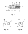
- FIGs. 15a, 15b show an adapter 1400 which may be used to extend the device actuation point (e.g . the hex cap 1314) forward to allow easy access with a tool such as a screwdriver.
- Such an adapter 1400 may have a proximal end 1402 comprising a hex or other similar tool head 1404, a distal end 1406 comprising a hex socket 1410 configured to engage hex cap 1314, and an intermediate universal joint 1408 configured to transmit a rotational input from the tool head 1404 to the hex socket 1410 while accommodating varying angles between the ends 1402, 1406.
- the adapter 1400 may be configured for permanent attachment to the device hex cap 1314, and as such would reside within the patient's mouth during the length of the distraction procedure.
- the adapter 1400 may be configured for temporary attachment to the hex cap 1314, and as such would be installed and used during the actual actuation process only.
- the adapter likewise may consist of various other temporary or permanent arrangements, for example the actuator may comprise a flexible rod attachment, or it could be a rigid adapter. It will be obvious that any kind of extension device known in the art may be used as appropriate to facilitate movement of the actuation point as far forward in the patient's mouth as practical for operation and to suit the comfort of the patient.
- actuation of the device may include the step of installing a universal or other type adapter which temporarily or permanently relocates the actuation point of the device
- the outer sleeve may be configured to accept a temporary alignment element for use in assuring proper fit and alignment of the device in a patient prior to final installation.
- the outer sleeve 1200 may incorporate external threads 1216 configured to engage corresponding internal threads of a temporary alignment element.
- the alignment element may comprise a tube or rod having a length, an engagement end having internal threads corresponding to the threads of the outer sleeve 1216, and a longitudinal axis coincident to the longitudinal axis "X-X" of the device actuator 1100 upon engagement with the outer sleeve.
- the alignment element should be long enough to allow a portion of the element to extend out from the patient's mouth when the device is initially fit to the patient. During this initial fitting step, the alignment element allows the surgeon to easily verify or take measurements of the expected distraction vector from outside the patient, prior to final attachment of the device to the maxilla and zygoma 21, 22.
- the alignment element may also be used by the surgeon as a convenient handle to hold the device during placement.
- the device of the above described embodiments may also be provided in the form of a kit.
- the kit comprises a plurality of proximal and distal footplates 800, 900, as well as a plurality of actuators 1100.
- the kit is provided with proximal footplates 800 having various individual or similar shapes, sizes, number of screw holes, material or other pertinent features.
- the kit is provided with distal footplates 900 having various individual or similar shapes, sizes, number of screw holes, material or other pertinent features.
- the plurality of distal footplates 900 each have a different sized intermediate portion 909 so that each distal footplate 900 may provide a different distance "C" between the distal end 911 of the distal footplate actuator engaging portion 910 and the distal footplate bone contacting surface 906.
- the kit may be provided with a plurality of actuation assemblies 1100, each configured to provide a unique distraction length.
- the footplates 800, 900 may attach to the actuation assembly 1100 using easily removable and connectable threaded connections.
- the pieces are interchangeable simply by unthreading the appropriate connection (e.g . the proximal footplate threaded bore 812 from the lead screw 1300, or the distal footplate machine screw 914 from the outer sleeve internally threaded bore 1208), then rebuilding the device using the desired piece or pieces.
- This easy interchangeability allows the surgeon to select from a wide variety of footplate sizes and geometries, as well as distraction vector lengths, to build a customized distractor to conform to the individual anatomy of a particular patient.
Landscapes
- Health & Medical Sciences (AREA)
- Orthopedic Medicine & Surgery (AREA)
- Life Sciences & Earth Sciences (AREA)
- Surgery (AREA)
- Medical Informatics (AREA)
- Engineering & Computer Science (AREA)
- Biomedical Technology (AREA)
- Heart & Thoracic Surgery (AREA)
- Nuclear Medicine, Radiotherapy & Molecular Imaging (AREA)
- Molecular Biology (AREA)
- Animal Behavior & Ethology (AREA)
- General Health & Medical Sciences (AREA)
- Public Health (AREA)
- Veterinary Medicine (AREA)
- Surgical Instruments (AREA)
- Orthopedics, Nursing, And Contraception (AREA)
Claims (26)
- Orthopädische Vorrichtung zum Separieren eines ersten und zweiten Knochensegments umfassend:eine erste Fussplatte (800) umfassend:einen Abschnitt (802) zur Befestigung an einem Knochen, der eine Knochenkontaktfläche (806) hat, wobei mindestens ein Abschnitt der Knochenkontaktfläche (806) eine erste Ebene definiert, und einen in ein Antriebsmittel eingreifenden Abschnitt (810);eine zweite Fussplatte (900) umfassend:einen Abschnitt (902) zur Befestigung an einem Knochen, der eine Knochenkontaktfläche (906) hat, wobei mindestens ein Abschnitt der Knochenkontaktfläche (906) eine zweite Ebene definiert, die im Wesentlichen nicht parallel zur ersten Ebene ist, und einen Abschnitt (910) zur Befestigung an einem Antriebsmittel; undAntriebsmittel (1100) mit einer Längsachse, einer Länge vor Betätigung und einer Länge nach Betätigung, wobei das Antriebsmittel so konfiguriert und angepasst ist,dass es unter Verwendung der ersten Fussplatte (800) an einem ersten Knochensegment und unter Verwendung der zweiten Fussplatte (900) an einem zweiten Knochensegment befestigbar ist, wobeidie Längsachse des Antriebsmittels im Wesentlichen nicht parallel zu der zweiten Ebene ist, der Abschnitt zur Befestigung an den Antriebsmitteln in einem vorbestimmten Abstand posterior zu der zweiten Ebene angeordnet ist; und die Längen des Antriebsmittels nach Betätigung und vor Betätigung im Wesentlichen gleich sind;dadurch gekennzeichnet, dassdie Antriebsmittel (1100) zusätzlich umfassen:eine Vortriebsschraube (1300) mit einem Aussengewinde, undeine äußere Hülse (1200), die einen axialen Schlitz und einen in die zweite Fussplatte eingreifenden Abschnitt hat, wobei die zweite Fussplatte (900) mit dem in die zweite Fussplatte eingreifenden Abschnitt verbunden ist; und wobei die erste Fussplatte zusätzlich einen in die Antriebsmittel eingreifenden Abschnitt (810) umfasst, der eine Bohrung mit Innengewinde und einen in den Schlitz der äußeren Hülse eingreifenden Abschnitt hat, wobei die Bohrung der ersten Fussplatte mit der Vortriebsschraube (1300) zusammenwirkt und der in den Schlitz der äusseren Hülse eingreifende Abschnitt der ersten Fussplatte mit dem axialen Schlitz der äußeren Hülse zusammenwirkt; wobeidie Vortriebsschraube (1300) und die äußere Hülse (1200) so verbunden sind, dass zwischen der Vortriebsschraube (1300) und der Hülse (1200) nur eine relative Rotationsbewegung um die Längsachse ermöglicht ist, so, dass ein Drehen der Vortriebsschraube (1300) eine Translationsbewegung der ersten Fussplatte relativ zu der äußeren Hülse (1200) entlang der Längsachse der Antriebsmittel verursacht.
- Orthopädische Vorrichtung nach Anspruch 1, dadurch gekennzeichnet, dass der vorbestimmte Abstand in einem Bereich von zwischen ungefähr 1 Millimeter (mm) bis ungefähr 25 mm liegt.
- Orthopädische Vorrichtung nach Anspruch 1, dadurch gekennzeichnet, dass der vorbestimmte Abstand in einem Bereich von zwischen ungefähr 7 mm bis ungefähr 12 mm liegt.
- Orthopädische Vorrichtung nach einem der Ansprüche 1-3, dadurch gekennzeichnet, dass mindestens eine Fussplatte deformierbar ist, um eine Formanpassung an die Oberfläche des entsprechenden Knochensegments zu ermöglichen.
- Orthopädische Vorrichtung nach einem der Ansprüche 1-4, dadurch gekennzeichnet, dass die Abschnitte zur Befestigung an einem Knochen der ersten und zweiten Fussplatte je mindestens ein Loch haben, das zur Aufnahme mindestens einer Knochenschraube für die Befestigung der jeweiligen Fussplatte am Knochen ausgebildet ist.
- Orthopädische Vorrichtung nach einem der Ansprüche 1-5, dadurch gekennzeichnet, dass mindestens ein Abschnitt mindestens einer Fussplatte aus einem bioresorbierbaren Material hergestellt ist.
- Orthopädische Vorrichtung nach Anspruch 6, dadurch gekennzeichnet, dass die mindestens eine Fussplatte durch mindestens ein bioresorbierbares Befestigungselement an dem entsprechenden Knochensegment angebracht wird.
- Orthopädische Vorrichtung nach einem der Ansprüche 1-7, dadurch gekennzeichnet, dass die erste Fussplatte so ausgebildet und angepasst ist, dass sie an einem Konstrukt anbringbar ist, wobei das Konstrukt mechanisch mit den Zähnen des Patienten verbunden ist.
- Orthopädische Vorrichtung nach einem der Ansprüche 1-8, zusätzlich umfassend ein Befestigungselement zur lösbaren Befestigung der zweiten Fussplatte an den Antriebsmitteln.
- Orthopädische Vorrichtung nach einem der Ansprüche 1-9, dadurch gekennzeichnet, dass der Befestigungsabschnitt der zweiten Fussplatte zusätzlich eine Bohrung mit einer Schulter umfasst und die Antriebsmittel zusätzlich ein distales Ende umfassen, das eine Gewindebohrung hat, und der Abschnitt zur Befestigung der Antriebsmittel an der zweiten Fussplatte in Eingriff mit den Antriebsmitteln ist, und der Gewindeabschnitt der Schraube in die Bohrung des Befestigungsabschnitts der zweiten Fussplatte eingesetzt ist und in die Gewindebohrung der Antriebsmittel eingreift.
- Orthopädische Vorrichtung nach einem der Ansprüche 1-10, dadurch gekennzeichnet, dass mindestens ein Abschnitt der ersten Fussplatte so ausgebildet ist, dass er an der Maxilla befestigbar ist und mindestens ein Abschnitt der zweiten Fussplatte so ausgebildet ist, dass er an dem Zygoma befestigbar ist.
- Orthopädische Vorrichtung nach einem der Ansprüche 1-11, dadurch gekennzeichnet, dass die Antriebsmittel eine Oberfläche haben, die ausgebildet ist, um in ein temporäres Ausrichtelement einzugreifen, um die Vorrichtung vor dem Anbringen an den Knochensegmenten auszurichten, und wobei die Vorrichtung so ausgebildet ist, dass sie intra-oral installierbar ist.
- Orthopädische Vorrichtung von Anspruch 12, dadurch gekennzeichnet, dass die Antriebsmittel eine ein Gewinde umfassende Oberfläche haben, das so ausgebildet ist, dass es in ein entsprechendes Gewinde des temporären Ausrichtelements eingreift.
- Orthopädische Vorrichtung von Anspruch 12, dadurch gekennzeichnet, dass die Antriebsmittel eine Oberfläche haben, die mit dem temporären Ausrichtelement verkeilt ist.
- Orthopädische Vorrichtung nach einem der Ansprüchen 1-14, dadurch gekennzeichnet, dass der in Eingriff mit den Antriebsmitteln stehende Abschnitt der zweiten Fussplatte zusätzlich so ausgebildet ist, dass der mit den Antriebsmitteln lösbar in Eingriff bringbar ist.
- Orthopädische Vorrichtung nach einem der Ansprüche 1-15, dadurch gekennzeichnet, dass mindestens eine der Fussplatten aus einem bioresorbierbaren Material hergestellt ist, und die Antriebsmittel aus einem nicht bioresorbierbaren Material hergestellt sind.
- Zusammenstellungs-Kit für eine orthopädisches Vorrichtung umfassend:(a) mindestens ein Antriebsmittel (110) nach einem der Ansprüche 1 - 16;(b) eine Mehrzahl von ersten Fussplatten (800) nach einem der Ansprüche 1 - 16, wobei jede einen Abschnitt für einen Eingriff in die Maxilla und einen in die Antriebsmittel eingreifenden Abschnitt hat, und wobei mindestens zwei der ersten Fussplatten (800) eine unterschiedliche Konfiguration haben; und(c) eine Mehrzahl von zweiten Fussplatten (900) nach einem der Ansprüche 1 - 16, wobei jede einen Abschnitt für einen Eingriff in das Zygoma und einen in die Antriebsmittel eingreifenden Abschnitt hat, wobei der Abschnitt für einen Eingriff in das Zygoma so ausgebildet ist, dass er ermöglicht, dass mindestens ein Abschnitt der Antriebsmittel in einem vorbestimmten Abstand posterior zum Zygoma angeordnet ist, und wobei mindestens zwei der zweiten Fussplatten (900) eine unterschiedliche Konfiguration haben,
dadurch gekennzeichnet, dass(d) mindestens je eine der ersten und der zweiten Fussplatten (800,900) austauschbar von den Antriebsmitteln entfernbar ist, um einem Chirurgen zu gestatten, eine angepasste Vorrichtung zusammenzustellen, die an die Anatomie eines bestimmten Patienten angepasst ist. - Kit nach Anspruch 17, dadurch gekennzeichnet, dass jeder Abschnitt für einen Eingriff in die Maxilla der ersten Fussplatte zusätzlich Schraubenlöcher umfasst, die zur Aufnahme von Knochenschrauben konfiguriert sind, und die Konfiguration solcher Schraubenlöcher für jede erste Fussplatte unterschiedlich ist.
- Kit nach Anspruch 17 oder 18, dadurch gekennzeichnet, dass die Abschnitte für einen Eingriff in die Maxilla von mindestens zwei der ersten Fussplatten eine unterschiedliche Form aufweisen.
- Kit nach einem der Ansprüche 17-19, dadurch gekennzeichnet, dass der Abschnitt für einen Eingriff in das Zygoma jeder der zweiten Fussplatten zusätzlich Schraubenlöcher umfasst, die zur Aufnahme von Knochenschrauben konfiguriert sind, und die Konfiguration solcher Schraubenlöcher für jede zweite Fussplatte unterschiedlich ist.
- Kit nach einem der Ansprüche 17-20, dadurch gekennzeichnet, dass die Abschnitte für einen Eingriff in das Zygoma von mindestens zwei der zweiten Fussplatten eine unterschiedliche Form aufweisen.
- Kit nach einem der Ansprüche 17-21, dadurch gekennzeichnet, dass mindestens eine zweite Fussplatte so konfiguriert ist, dass ermöglicht wird, den Antriebsaufbau verglichen mit mindestens einer anderen zweiten Fussplatte um einen unterschiedlichen Betrag posterior zum Zygoma anzuordnen.
- Kit nach einem der Ansprüche 17-22, dadurch gekennzeichnet, dass der vorbestimmte Abstand im Bereich von ungefähr 1 mm bis ungefähr 25 mm liegt.
- Kit nach einem der Ansprüche 17-22, dadurch gekennzeichnet, dass der vorbestimmte Abstand im Bereich von ungefähr 7 mm bis ungefähr 12 mm liegt.
- Kit einem der Ansprüche 17-24, dadurch gekennzeichnet, dass der in die Antriebsmittel eingreifende Abschnitt jeder zweiten Fussplatte konfiguriert ist, um in ein distales Ende der mindestens einen Antriebsmittel einzugreifen, und der mindestens eine Antriebsaufbau zusätzlich umfasst:eine Vortriebsschraube mit einem Aussengewinde, und eine äußere Hülse, die einen axialen Schlitz und einen in die zweite Fussplatte eingreifenden Abschnitt hat; wobei die zweite Fussplatte mit dem in die zweite Fussplatte eingreifenden Abschnitt verbunden ist; undjede erste Fussplatte zusätzlich einen in die Antriebsmittel eingreifenden Abschnitt umfasst, der eine Bohrung mit Innengewinde und einen in den Schlitz der äusseren Hülse eingreifenden Abschnitt hat, wobei die Bohrung der ersten Fussplatte mit der Vortriebsschraube zusammenwirkt und der in den Schlitz der äusseren Hülse eingreifende Abschnitt der ersten Fussplatte mit dem axialen Schlitz der äusseren Hülse zusammenwirkt;wobei die Vortriebsschraube und die äußere Hülse so verbunden sind, dass zwischen der Schraube und der Hülse nur eine relative Rotationsbewegung um die Längsachse möglich ist, so, dass eine Umdrehung der Vortriebsschraube eine Translationsbewegung der ersten Fussplatte relativ zu der äußeren Hülse entlang der Längsachse der Antriebsmittel verursacht.
- Kit nach einem der Ansprüche 17-25, zusätzlich umfassend eine Mehrzahl von temporären Ausrichtelementen, die so konfiguriert sind, dass sie mit der orthopädischen Vorrichtung lösbar in Eingriff bringbar sind, um eine in-situ Ausrichtung der orthopädischen Vorrichtung zu ermöglichen.
Priority Applications (1)
| Application Number | Priority Date | Filing Date | Title |
|---|---|---|---|
| EP10006527A EP2229901A1 (de) | 2002-04-30 | 2003-04-29 | Kompakte Kieferknochen-Distraktionsvorrichtung |
Applications Claiming Priority (3)
| Application Number | Priority Date | Filing Date | Title |
|---|---|---|---|
| US135281 | 1980-03-31 | ||
| US10/135,281 US6908469B2 (en) | 2000-10-04 | 2002-04-30 | Compact maxillary distractor |
| PCT/US2003/013238 WO2003092519A1 (en) | 2002-04-30 | 2003-04-29 | Compact maxillary distractor |
Related Child Applications (1)
| Application Number | Title | Priority Date | Filing Date |
|---|---|---|---|
| EP10006527.5 Division-Into | 2010-06-23 |
Publications (2)
| Publication Number | Publication Date |
|---|---|
| EP1499250A1 EP1499250A1 (de) | 2005-01-26 |
| EP1499250B1 true EP1499250B1 (de) | 2011-02-02 |
Family
ID=29399217
Family Applications (2)
| Application Number | Title | Priority Date | Filing Date |
|---|---|---|---|
| EP03728593A Expired - Lifetime EP1499250B1 (de) | 2002-04-30 | 2003-04-29 | Kompakte kieferknochen-distraktionsvorrichtung |
| EP10006527A Withdrawn EP2229901A1 (de) | 2002-04-30 | 2003-04-29 | Kompakte Kieferknochen-Distraktionsvorrichtung |
Family Applications After (1)
| Application Number | Title | Priority Date | Filing Date |
|---|---|---|---|
| EP10006527A Withdrawn EP2229901A1 (de) | 2002-04-30 | 2003-04-29 | Kompakte Kieferknochen-Distraktionsvorrichtung |
Country Status (11)
| Country | Link |
|---|---|
| US (1) | US6908469B2 (de) |
| EP (2) | EP1499250B1 (de) |
| JP (1) | JP4594079B2 (de) |
| AR (1) | AR039513A1 (de) |
| AT (1) | ATE497369T1 (de) |
| AU (1) | AU2003234280A1 (de) |
| BR (1) | BR0309723A (de) |
| CA (1) | CA2483583C (de) |
| DE (1) | DE60335944D1 (de) |
| MX (1) | MXPA04010743A (de) |
| WO (1) | WO2003092519A1 (de) |
Families Citing this family (58)
| Publication number | Priority date | Publication date | Assignee | Title |
|---|---|---|---|---|
| US6972020B1 (en) * | 2001-06-01 | 2005-12-06 | New York University | Multi-directional internal distraction osteogenesis device |
| US7097645B2 (en) * | 2001-06-04 | 2006-08-29 | Sdgi Holdings, Inc. | Dynamic single-lock anterior cervical plate system having non-detachably fastened and moveable segments |
| CA2443429C (en) | 2001-06-04 | 2010-08-10 | Gary Karlin Michelson | Anterior cervical plate system having vertebral body engaging anchors, connecting plate, and method for installation thereof |
| CA2443425C (en) * | 2001-06-04 | 2009-09-15 | Gary Karlin Michelson | Dynamic anterior cervical plate system having moveable segments and instrumentation therefor |
| US7186256B2 (en) * | 2001-06-04 | 2007-03-06 | Warsaw Orthopedic, Inc. | Dynamic, modular, single-lock anterior cervical plate system having assembleable and movable segments |
| US7041105B2 (en) * | 2001-06-06 | 2006-05-09 | Sdgi Holdings, Inc. | Dynamic, modular, multilock anterior cervical plate system having detachably fastened assembleable and moveable segments |
| US7044952B2 (en) * | 2001-06-06 | 2006-05-16 | Sdgi Holdings, Inc. | Dynamic multilock anterior cervical plate system having non-detachably fastened and moveable segments |
| US7621922B2 (en) * | 2001-11-20 | 2009-11-24 | Osteomed L.P. | Facial osteodistraction device |
| US7892241B2 (en) * | 2001-11-20 | 2011-02-22 | Osteomed, L.P. | Method and system for facial osteodistraction using a cannulated device |
| GB0405386D0 (en) * | 2004-03-10 | 2004-04-21 | Depuy Int Ltd | Device |
| US7182785B2 (en) * | 2004-03-11 | 2007-02-27 | Craniotech Acr Devices, Llc | Mandibular bone transport reconstruction plate |
| JP4980881B2 (ja) * | 2004-03-26 | 2012-07-18 | ジンテーズ ゲゼルシャフト ミト ベシュレンクテル ハフツング | 継手付き骨ねじ |
| US7485121B2 (en) * | 2004-05-04 | 2009-02-03 | Synthes (Usa) | Midface distractor |
| US7686836B2 (en) * | 2004-05-13 | 2010-03-30 | Kls-Martin, L.P. | Bone distractor and method |
| US7875033B2 (en) * | 2004-07-19 | 2011-01-25 | Synthes Usa, Llc | Bone distraction apparatus |
| US7901409B2 (en) * | 2006-01-20 | 2011-03-08 | Canaveral Villegas Living Trust | Intramedullar devices and methods to reduce and/or fix damaged bone |
| CN100384383C (zh) * | 2006-07-17 | 2008-04-30 | 中国人民解放军第二炮兵总医院 | 一种用于眶下壁骨折复位固定的医疗器械 |
| US7909610B1 (en) | 2006-12-21 | 2011-03-22 | Amato Craniofacial Engineering, LLC | Computer-aided system of orthopedic surgery |
| US8029523B2 (en) * | 2007-03-30 | 2011-10-04 | Innovative Implant Technology, Llc | Maxillary bone cutting system, kit, and method of using the same |
| US20090192514A1 (en) * | 2007-10-09 | 2009-07-30 | Feinberg Stephen E | Implantable distraction osteogenesis device and methods of using same |
| JP5404635B2 (ja) * | 2007-10-25 | 2014-02-05 | ノベル バイオケア サーヴィシィズ アーゲー | 伸延装置 |
| US20090186314A1 (en) * | 2008-01-17 | 2009-07-23 | Richard Pober | Dental distractor |
| US20100075270A1 (en) * | 2008-09-19 | 2010-03-25 | Figueroa Alvaro A | Angularly adjustable maxillary distractor and method of distraction |
| US20100104999A1 (en) * | 2008-10-23 | 2010-04-29 | Bulloch Scott E | Apparatus, System, and Method for Intra-Oral Distraction |
| KR101154612B1 (ko) | 2009-10-23 | 2012-06-08 | 지웰전자 주식회사 | 턱뼈 신장 장치 |
| WO2011095956A2 (en) * | 2010-02-08 | 2011-08-11 | Rajiv Agarwal | System and methods for bone distraction |
| US9066733B2 (en) * | 2010-04-29 | 2015-06-30 | DePuy Synthes Products, Inc. | Orthognathic implant and methods of use |
| US8764441B2 (en) * | 2010-07-21 | 2014-07-01 | John W. Polley | Method and internal apparatus for determining final position of dentate skeleton in orthognathic surgery |
| KR101154618B1 (ko) | 2011-03-16 | 2012-06-08 | 동국대학교 산학협력단 | 교정용 하악 유도 악기능 장치 |
| US9308026B2 (en) * | 2011-04-20 | 2016-04-12 | Ramon L. Ruiz | Distractor device including multiple diameter internal post and related methods |
| WO2012149087A1 (en) * | 2011-04-26 | 2012-11-01 | Synthes Usa, Llc | Hinged fixation devices for combined upper jaw correction |
| AU2012202977B2 (en) | 2011-05-23 | 2016-02-11 | Coceancig, Paul Lloyd G. | A distractor device and a method for distracting a jaw bone |
| EP2768412A1 (de) * | 2011-10-18 | 2014-08-27 | Biomet Manufacturing Corp. | Kompressives plattierungsverfahren für den distalen teil des oberarmknochens |
| KR200467239Y1 (ko) * | 2012-01-05 | 2013-06-03 | 주식회사 제일메디칼코퍼레이션 | 골신장기 |
| RU2489981C1 (ru) * | 2012-04-02 | 2013-08-20 | федеральное государственное бюджетное учреждение "Центральный научно-исследовательский институт стоматологии и челюстно-лицевой хирургии" Министерства здравоохранения Российской Федерации | Минипластина l-образной формы для остеосинтеза верхней челюсти после остеотомии |
| RU2489982C1 (ru) * | 2012-04-02 | 2013-08-20 | федеральное государственное бюджетное учреждение "Центральный научно-исследовательский институт стоматологии и челюстно-лицевой хирургии" Министерства здравоохранения Российской Федерации (ФГБУ "ЦНИИС и ЧЛХ" Минздрава России) | Мини-пластина для остеосинтеза после мультисегментной остеотомии верхней челюсти |
| KR101207130B1 (ko) | 2012-04-27 | 2012-11-30 | 지웰전자 주식회사 | 턱뼈 신장 시스템 및 그 제어방법 |
| US10709482B2 (en) * | 2012-05-30 | 2020-07-14 | Globus Medical, Inc. | Laminoplasty system |
| EP2735276B1 (de) | 2012-11-27 | 2018-09-05 | Stryker European Holdings I, LLC | Pädiatrischer interner Mandibulardistraktor |
| EP2742883B1 (de) | 2012-12-12 | 2016-07-27 | Stryker European Holdings I, LLC | Chirurgieabstandseinstellungsbaugruppe für Knochendistraktor |
| WO2015187123A1 (en) * | 2014-06-02 | 2015-12-10 | Albany Medical College | Dynamic decompressive craniotomy fixation devices and related methods |
| DE102014014096A1 (de) * | 2014-09-23 | 2016-03-24 | Celgen Ag | Distraktionsimplantat mit verbessertem Mechanismus |
| US9931138B2 (en) * | 2014-10-15 | 2018-04-03 | Globus Medical, Inc. | Orthopedic extendable rods |
| JP6445711B2 (ja) * | 2014-11-05 | 2018-12-26 | ジュニア, トーマス, エス. ジョンストン, | 延長装置用の取り外し可能なアクチュエータアーム |
| US10166053B2 (en) | 2014-12-30 | 2019-01-01 | Stryker European Holdings I, Llc | Distractor with bidirectional rotation control |
| JP2016174659A (ja) * | 2015-03-19 | 2016-10-06 | タキロン株式会社 | 骨固定用プレート |
| AU2015101689B4 (en) | 2015-03-20 | 2016-04-28 | Lambert, Geoffrey James MR | Mandibular reposition device and coupling therefor |
| US9649132B1 (en) | 2015-04-20 | 2017-05-16 | Donald W. Linck | Bone distractor |
| CN109069187B (zh) * | 2016-07-14 | 2022-01-18 | Amdt控股公司 | 骨外固定系统 |
| WO2019104255A1 (en) | 2017-11-24 | 2019-05-31 | Craniofacial Technologies Inc. | Improved maxillary expander and protraction device |
| US10575926B2 (en) | 2017-11-24 | 2020-03-03 | Craniofacial Technologies, Inc. | Maxillary expander |
| WO2019178008A1 (en) * | 2018-03-11 | 2019-09-19 | Craniofacial Technologies Inc. | System and method for treating maxillary deficiencies |
| IL260367A (en) * | 2018-07-02 | 2018-08-30 | Osteophile Ltd | Devices, systems and methods for bone lengthening |
| BR112021003874A2 (pt) * | 2018-08-29 | 2021-05-18 | Amdt Holdings, Inc. | conjuntos de suporte ajustáveis para sistemas de fixação externos |
| US11141245B2 (en) * | 2019-02-07 | 2021-10-12 | Dan Rosen | Angled dental implant with angled anchor point |
| CN113180810B (zh) * | 2021-04-06 | 2023-04-07 | 四川大学 | 颧骨颧弓切开内推整形手术用接骨板 |
| US11553948B2 (en) | 2021-05-20 | 2023-01-17 | University Of Utah Research Foundation | Bone fixation devices, systems, and methods |
| CN113558794B (zh) * | 2021-07-26 | 2022-07-08 | 首都医科大学附属北京口腔医院 | 一种牙骨混合支持式外置口内牵张成骨器及使用方法 |
Family Cites Families (55)
| Publication number | Priority date | Publication date | Assignee | Title |
|---|---|---|---|---|
| US4144643A (en) | 1977-01-19 | 1979-03-20 | Krygier Stanley J | Maxillary orthopedic suture separating orthodontic appliance |
| US4187841A (en) | 1978-07-07 | 1980-02-12 | Knutson Richard A | Bone compression or distraction device |
| DE3301753C2 (de) | 1982-04-08 | 1985-01-31 | Bernhard Förster GmbH, 7530 Pforzheim | Dehnschraube zur Zahnregulierung |
| CH657037A5 (fr) | 1984-02-13 | 1986-08-15 | Rodam Sa | Verin orthodontique pour appareil d'expansion des arcades dentaires. |
| DE3601715A1 (de) * | 1986-01-22 | 1987-07-23 | Heinl Thomas | Chirurgisches instrumentenset zum verbinden von knochenfragmenten |
| DE8807909U1 (de) | 1988-06-18 | 1988-10-20 | Howmedica Gmbh, 2314 Schoenkirchen, De | |
| DE4018273A1 (de) | 1989-07-06 | 1991-01-17 | Schwestka Rainer Dr Med Dent | Verfahren zur herstellung von operationssplinten und vorrichtung zum positionieren von kieferteilen bei zentriertem kiefergelenk |
| DE4007306C1 (en) | 1990-03-08 | 1991-05-23 | Eska Medical Luebeck Medizintechnik Gmbh & Co, 2400 Luebeck, De | Implant for use in bone surgery - comprises two plates geared to allow relative external adjustment after fixture |
| US5147358A (en) | 1990-10-23 | 1992-09-15 | Remmler Daniel J | Cranial fixation-distraction and positioning apparatus and method |
| CA2093828A1 (en) | 1992-04-16 | 1993-10-17 | Anthony Philip Pohl | External bone fixation device |
| DE4219156A1 (de) | 1992-06-11 | 1993-12-16 | Leibinger Gmbh | Vorrichtung zum Fixieren der Relativstellung von Knochen |
| US5885283A (en) | 1992-08-04 | 1999-03-23 | Gittleman; Neal B. | Osteogenic mandibular distention apparatus and method |
| US5364396A (en) | 1993-03-29 | 1994-11-15 | Robinson Randolph C | Distraction method and apparatus |
| DE4316794C1 (de) | 1993-05-19 | 1994-10-13 | Joerg Bischof | Vorrichtung zur Distraktion von Knochen |
| US6187004B1 (en) | 1993-07-14 | 2001-02-13 | Jeffrey A. Fearon | Subcutaneous bone expansion device |
| US5328364A (en) | 1993-10-15 | 1994-07-12 | Doyle Walter A | Dental clamp |
| FR2715291B1 (fr) | 1994-01-21 | 1996-06-07 | Michel Allard | Dispositif d'ostéosynthèse. |
| US5829971A (en) | 1994-04-04 | 1998-11-03 | Razdolsky; Yan | Osteodistraction device for use in mandibular distraction osteogenesis and a method of making the device |
| US5616142A (en) | 1994-07-20 | 1997-04-01 | Yuan; Hansen A. | Vertebral auxiliary fixation device |
| DE29501880U1 (de) | 1995-02-06 | 1995-05-24 | Leibinger Medizintech | Vorrichtung zur Knochenverlängerung |
| EP0770359A1 (de) | 1995-10-05 | 1997-05-02 | Medicon e.G. Chirurgiemechaniker-Genossenschaft | Distraktionsvorrichtung für Knochensegmente |
| DE19538323A1 (de) | 1995-10-14 | 1997-04-17 | Mueller Paul A | Zugapparat zur Korrektur eines Oberkiefers |
| AU715921B2 (en) | 1995-12-01 | 2000-02-10 | Gurkan Altuna | Telescopic bone plate for use in bone lengthening by distraction osteogenesis |
| US5700263A (en) | 1996-06-17 | 1997-12-23 | Schendel; Stephen A. | Bone distraction apparatus |
| US5906644A (en) * | 1996-08-30 | 1999-05-25 | Powell; Douglas Hunter | Adjustable modular orthopedic implant |
| BE1010602A4 (nl) | 1996-09-04 | 1998-11-03 | Mommaerts Maurice Yves | Apparaat voor intraorale distractieosteotomie. |
| US5895387A (en) | 1996-10-09 | 1999-04-20 | Romulo Guerrero | Method of craniofacial bone distraction |
| US5769850A (en) | 1996-10-16 | 1998-06-23 | Chin; Martin | Apparatus and method for submergible, self-retaining distraction osteogenesis |
| US5976142A (en) | 1996-10-16 | 1999-11-02 | Chin; Martin | Apparatus and method for distraction osteogenesis of small alveolar bone |
| US5885290A (en) * | 1996-12-09 | 1999-03-23 | Guerrero; Cesar A. | Intra-oral bone distraction device |
| IT1298413B1 (it) * | 1997-05-21 | 2000-01-05 | Orthofix Srl | Dispositivo minifissatore esterno per il trattamento di ossa piccole |
| US6113599A (en) | 1997-06-04 | 2000-09-05 | Kalpa Engineering, Inc. | Apparatus for internal mandibular distraction |
| EP0998237B1 (de) | 1997-07-21 | 2003-10-01 | Roger Minoretti | Intraoraler distraktor für kallusdistraktion im unterkiefer |
| DE19731921C2 (de) | 1997-07-25 | 2000-04-20 | Eska Implants Gmbh & Co | Bidirektionaler Unterkieferdistraktor |
| DE29716635U1 (de) | 1997-09-16 | 1997-10-30 | Leibinger Medizintech | Distraktionsvorrichtung zur Behandlung von Knochendefekten |
| DE19741757A1 (de) | 1997-09-22 | 1999-03-25 | Sachse Hans E | Hydraulisches, implantierbares Knochenexpansionsgerät |
| US6086365A (en) | 1998-02-02 | 2000-07-11 | Walter Lorenz Surgical, Inc. | Bonded intermaxillary fixation splint |
| US6241517B1 (en) | 1998-04-23 | 2001-06-05 | Michael O. Williams | Mandibular and maxillary arch expander |
| US6171313B1 (en) | 1998-07-02 | 2001-01-09 | Yan Razdolsky | Distraction apparatus for subapical osteotomy and vertical segment distraction and ridge augmentation |
| US5873715A (en) | 1998-07-20 | 1999-02-23 | Liou; Eric Jein-Wein | Dental distractor |
| DE29813087U1 (de) | 1998-07-22 | 1998-12-24 | Leibinger Medizintech | Distraktionsvorrichtung |
| FR2787698B1 (fr) | 1998-10-27 | 2001-05-18 | Obl | Distracteur mandibulaire intraoral |
| DE19856062A1 (de) | 1998-12-04 | 2000-06-15 | Wittenstein Gmbh & Co Kg | Distraktionsvorrichtung |
| US6139316A (en) | 1999-01-26 | 2000-10-31 | Sachdeva; Rohit C. L. | Device for bone distraction and tooth movement |
| EP1027868A1 (de) | 1999-02-09 | 2000-08-16 | Paul A. Dr. med. Müller | Zugapparat zur Korrektur eines Kiefers |
| US6423069B1 (en) | 1999-03-23 | 2002-07-23 | Synthes (Usa) | Orthopedic system having detachable bone anchors |
| US6217323B1 (en) | 1999-08-18 | 2001-04-17 | Eric Jein-Wein Liou | Dental distractor |
| DE29921046U1 (de) | 1999-11-30 | 2000-05-11 | Leibinger Medizintech | Knochendistraktor |
| US7771427B2 (en) | 1999-12-09 | 2010-08-10 | Macropore | Partially resorbable connective tissue distraction devices and techniques |
| US6293947B1 (en) | 2000-01-28 | 2001-09-25 | Daniel Buchbinder | Distraction osteogenesis device and method |
| US6471706B1 (en) * | 2000-04-18 | 2002-10-29 | Walter Lorenz Surgical, Inc. | Resorbable bone distractor and method |
| DE20008797U1 (de) | 2000-05-16 | 2000-08-03 | Leibinger Medizintech | Knochendistraktor |
| DE20008796U1 (de) | 2000-05-16 | 2000-08-03 | Leibinger Medizintech | Knochendistraktor |
| DE20012536U1 (de) | 2000-07-19 | 2001-01-11 | Leibinger Medizintech | Vorrichtung zur Distraktion von mindestens zwei Knochensegmenten |
| AR033840A1 (es) * | 2000-10-04 | 2004-01-07 | Synthes Ag | Un aparato ortopedico para modificar la distancia entre el maxilar y el cigoma de un paciente |
-
2002
- 2002-04-30 US US10/135,281 patent/US6908469B2/en not_active Expired - Lifetime
-
2003
- 2003-04-29 DE DE60335944T patent/DE60335944D1/de not_active Expired - Lifetime
- 2003-04-29 MX MXPA04010743A patent/MXPA04010743A/es not_active Application Discontinuation
- 2003-04-29 AT AT03728593T patent/ATE497369T1/de not_active IP Right Cessation
- 2003-04-29 CA CA2483583A patent/CA2483583C/en not_active Expired - Fee Related
- 2003-04-29 EP EP03728593A patent/EP1499250B1/de not_active Expired - Lifetime
- 2003-04-29 JP JP2004500709A patent/JP4594079B2/ja not_active Expired - Fee Related
- 2003-04-29 BR BR0309723-4A patent/BR0309723A/pt not_active IP Right Cessation
- 2003-04-29 WO PCT/US2003/013238 patent/WO2003092519A1/en active Application Filing
- 2003-04-29 EP EP10006527A patent/EP2229901A1/de not_active Withdrawn
- 2003-04-29 AU AU2003234280A patent/AU2003234280A1/en not_active Abandoned
- 2003-04-30 AR ARP030101526A patent/AR039513A1/es unknown
Also Published As
| Publication number | Publication date |
|---|---|
| MXPA04010743A (es) | 2005-03-07 |
| JP4594079B2 (ja) | 2010-12-08 |
| EP2229901A1 (de) | 2010-09-22 |
| US6908469B2 (en) | 2005-06-21 |
| ATE497369T1 (de) | 2011-02-15 |
| AU2003234280A1 (en) | 2003-11-17 |
| CA2483583A1 (en) | 2003-11-13 |
| EP1499250A1 (de) | 2005-01-26 |
| AR039513A1 (es) | 2005-02-23 |
| DE60335944D1 (de) | 2011-03-17 |
| WO2003092519A1 (en) | 2003-11-13 |
| US20020156485A1 (en) | 2002-10-24 |
| JP2005523765A (ja) | 2005-08-11 |
| BR0309723A (pt) | 2005-02-09 |
| CA2483583C (en) | 2012-07-03 |
Similar Documents
| Publication | Publication Date | Title |
|---|---|---|
| EP1499250B1 (de) | Kompakte kieferknochen-distraktionsvorrichtung | |
| US11751911B2 (en) | Intermaxillary fixation device and method of using same | |
| US10433887B2 (en) | Hinged fixation devices for combined upper jaw correction | |
| US5954769A (en) | Surgical drill positioning guide | |
| US5885290A (en) | Intra-oral bone distraction device | |
| CA2424108C (en) | Maxillary distractor | |
| JP4230697B2 (ja) | 骨セグメントの歯止め調節のための方法及び装置 | |
| EP1162919B1 (de) | Orthopädisches system mit ablösbaren knochenankern | |
| US7235077B1 (en) | Bone fixation device and method | |
| WO2011053520A1 (en) | Compression plate kit and methods for repairing bone discontinuities | |
| JP2012528677A (ja) | 髄内固定具アセンブリ及び関連方法 | |
| US7347687B2 (en) | Distraction apparatus for orthodontic, orthognathic and oral/maxillofacial surgery applications on the mandible |
Legal Events
| Date | Code | Title | Description |
|---|---|---|---|
| PUAI | Public reference made under article 153(3) epc to a published international application that has entered the european phase |
Free format text: ORIGINAL CODE: 0009012 |
|
| 17P | Request for examination filed |
Effective date: 20040930 |
|
| AK | Designated contracting states |
Kind code of ref document: A1 Designated state(s): AT BE BG CH CY CZ DE DK EE ES FI FR GB GR HU IE IT LI LU MC NL PT RO SE SI SK TR |
|
| AX | Request for extension of the european patent |
Extension state: AL LT LV MK |
|
| RAP1 | Party data changed (applicant data changed or rights of an application transferred) |
Owner name: SYNTHES GMBH |
|
| 17Q | First examination report despatched |
Effective date: 20100324 |
|
| GRAP | Despatch of communication of intention to grant a patent |
Free format text: ORIGINAL CODE: EPIDOSNIGR1 |
|
| GRAS | Grant fee paid |
Free format text: ORIGINAL CODE: EPIDOSNIGR3 |
|
| GRAA | (expected) grant |
Free format text: ORIGINAL CODE: 0009210 |
|
| GRAL | Information related to payment of fee for publishing/printing deleted |
Free format text: ORIGINAL CODE: EPIDOSDIGR3 |
|
| GRAS | Grant fee paid |
Free format text: ORIGINAL CODE: EPIDOSNIGR3 |
|
| AK | Designated contracting states |
Kind code of ref document: B1 Designated state(s): AT BE BG CH CY CZ DE DK EE ES FI FR GB GR HU IE IT LI LU MC NL PT RO SE SI SK TR |
|
| REG | Reference to a national code |
Ref country code: GB Ref legal event code: FG4D |
|
| REG | Reference to a national code |
Ref country code: CH Ref legal event code: NV Representative=s name: DR. LUSUARDI AG Ref country code: CH Ref legal event code: EP |
|
| REG | Reference to a national code |
Ref country code: IE Ref legal event code: FG4D |
|
| REF | Corresponds to: |
Ref document number: 60335944 Country of ref document: DE Date of ref document: 20110317 Kind code of ref document: P |
|
| REG | Reference to a national code |
Ref country code: DE Ref legal event code: R096 Ref document number: 60335944 Country of ref document: DE Effective date: 20110317 |
|
| REG | Reference to a national code |
Ref country code: NL Ref legal event code: VDEP Effective date: 20110202 |
|
| PG25 | Lapsed in a contracting state [announced via postgrant information from national office to epo] |
Ref country code: ES Free format text: LAPSE BECAUSE OF FAILURE TO SUBMIT A TRANSLATION OF THE DESCRIPTION OR TO PAY THE FEE WITHIN THE PRESCRIBED TIME-LIMIT Effective date: 20110513 Ref country code: GR Free format text: LAPSE BECAUSE OF FAILURE TO SUBMIT A TRANSLATION OF THE DESCRIPTION OR TO PAY THE FEE WITHIN THE PRESCRIBED TIME-LIMIT Effective date: 20110503 Ref country code: SE Free format text: LAPSE BECAUSE OF FAILURE TO SUBMIT A TRANSLATION OF THE DESCRIPTION OR TO PAY THE FEE WITHIN THE PRESCRIBED TIME-LIMIT Effective date: 20110202 Ref country code: PT Free format text: LAPSE BECAUSE OF FAILURE TO SUBMIT A TRANSLATION OF THE DESCRIPTION OR TO PAY THE FEE WITHIN THE PRESCRIBED TIME-LIMIT Effective date: 20110602 |
|
| PG25 | Lapsed in a contracting state [announced via postgrant information from national office to epo] |
Ref country code: BE Free format text: LAPSE BECAUSE OF FAILURE TO SUBMIT A TRANSLATION OF THE DESCRIPTION OR TO PAY THE FEE WITHIN THE PRESCRIBED TIME-LIMIT Effective date: 20110202 Ref country code: CY Free format text: LAPSE BECAUSE OF FAILURE TO SUBMIT A TRANSLATION OF THE DESCRIPTION OR TO PAY THE FEE WITHIN THE PRESCRIBED TIME-LIMIT Effective date: 20110202 Ref country code: AT Free format text: LAPSE BECAUSE OF FAILURE TO SUBMIT A TRANSLATION OF THE DESCRIPTION OR TO PAY THE FEE WITHIN THE PRESCRIBED TIME-LIMIT Effective date: 20110202 Ref country code: FI Free format text: LAPSE BECAUSE OF FAILURE TO SUBMIT A TRANSLATION OF THE DESCRIPTION OR TO PAY THE FEE WITHIN THE PRESCRIBED TIME-LIMIT Effective date: 20110202 Ref country code: BG Free format text: LAPSE BECAUSE OF FAILURE TO SUBMIT A TRANSLATION OF THE DESCRIPTION OR TO PAY THE FEE WITHIN THE PRESCRIBED TIME-LIMIT Effective date: 20110502 Ref country code: SI Free format text: LAPSE BECAUSE OF FAILURE TO SUBMIT A TRANSLATION OF THE DESCRIPTION OR TO PAY THE FEE WITHIN THE PRESCRIBED TIME-LIMIT Effective date: 20110202 Ref country code: NL Free format text: LAPSE BECAUSE OF FAILURE TO SUBMIT A TRANSLATION OF THE DESCRIPTION OR TO PAY THE FEE WITHIN THE PRESCRIBED TIME-LIMIT Effective date: 20110202 |
|
| PG25 | Lapsed in a contracting state [announced via postgrant information from national office to epo] |
Ref country code: DK Free format text: LAPSE BECAUSE OF FAILURE TO SUBMIT A TRANSLATION OF THE DESCRIPTION OR TO PAY THE FEE WITHIN THE PRESCRIBED TIME-LIMIT Effective date: 20110202 Ref country code: EE Free format text: LAPSE BECAUSE OF FAILURE TO SUBMIT A TRANSLATION OF THE DESCRIPTION OR TO PAY THE FEE WITHIN THE PRESCRIBED TIME-LIMIT Effective date: 20110202 |
|
| PG25 | Lapsed in a contracting state [announced via postgrant information from national office to epo] |
Ref country code: RO Free format text: LAPSE BECAUSE OF FAILURE TO SUBMIT A TRANSLATION OF THE DESCRIPTION OR TO PAY THE FEE WITHIN THE PRESCRIBED TIME-LIMIT Effective date: 20110202 Ref country code: MC Free format text: LAPSE BECAUSE OF NON-PAYMENT OF DUE FEES Effective date: 20110430 Ref country code: CZ Free format text: LAPSE BECAUSE OF FAILURE TO SUBMIT A TRANSLATION OF THE DESCRIPTION OR TO PAY THE FEE WITHIN THE PRESCRIBED TIME-LIMIT Effective date: 20110202 Ref country code: SK Free format text: LAPSE BECAUSE OF FAILURE TO SUBMIT A TRANSLATION OF THE DESCRIPTION OR TO PAY THE FEE WITHIN THE PRESCRIBED TIME-LIMIT Effective date: 20110202 |
|
| PLBE | No opposition filed within time limit |
Free format text: ORIGINAL CODE: 0009261 |
|
| STAA | Information on the status of an ep patent application or granted ep patent |
Free format text: STATUS: NO OPPOSITION FILED WITHIN TIME LIMIT |
|
| 26N | No opposition filed |
Effective date: 20111103 |
|
| REG | Reference to a national code |
Ref country code: IE Ref legal event code: MM4A |
|
| REG | Reference to a national code |
Ref country code: DE Ref legal event code: R097 Ref document number: 60335944 Country of ref document: DE Effective date: 20111103 |
|
| PG25 | Lapsed in a contracting state [announced via postgrant information from national office to epo] |
Ref country code: IE Free format text: LAPSE BECAUSE OF NON-PAYMENT OF DUE FEES Effective date: 20110429 |
|
| PG25 | Lapsed in a contracting state [announced via postgrant information from national office to epo] |
Ref country code: LU Free format text: LAPSE BECAUSE OF NON-PAYMENT OF DUE FEES Effective date: 20110429 |
|
| PG25 | Lapsed in a contracting state [announced via postgrant information from national office to epo] |
Ref country code: TR Free format text: LAPSE BECAUSE OF FAILURE TO SUBMIT A TRANSLATION OF THE DESCRIPTION OR TO PAY THE FEE WITHIN THE PRESCRIBED TIME-LIMIT Effective date: 20110202 |
|
| PG25 | Lapsed in a contracting state [announced via postgrant information from national office to epo] |
Ref country code: HU Free format text: LAPSE BECAUSE OF FAILURE TO SUBMIT A TRANSLATION OF THE DESCRIPTION OR TO PAY THE FEE WITHIN THE PRESCRIBED TIME-LIMIT Effective date: 20110202 |
|
| REG | Reference to a national code |
Ref country code: FR Ref legal event code: PLFP Year of fee payment: 14 |
|
| REG | Reference to a national code |
Ref country code: FR Ref legal event code: PLFP Year of fee payment: 15 |
|
| PGFP | Annual fee paid to national office [announced via postgrant information from national office to epo] |
Ref country code: FR Payment date: 20170313 Year of fee payment: 15 |
|
| PGFP | Annual fee paid to national office [announced via postgrant information from national office to epo] |
Ref country code: CH Payment date: 20170412 Year of fee payment: 15 Ref country code: GB Payment date: 20170426 Year of fee payment: 15 Ref country code: DE Payment date: 20170426 Year of fee payment: 15 |
|
| PGFP | Annual fee paid to national office [announced via postgrant information from national office to epo] |
Ref country code: IT Payment date: 20170420 Year of fee payment: 15 |
|
| REG | Reference to a national code |
Ref country code: DE Ref legal event code: R119 Ref document number: 60335944 Country of ref document: DE |
|
| REG | Reference to a national code |
Ref country code: CH Ref legal event code: PL |
|
| GBPC | Gb: european patent ceased through non-payment of renewal fee |
Effective date: 20180429 |
|
| PG25 | Lapsed in a contracting state [announced via postgrant information from national office to epo] |
Ref country code: DE Free format text: LAPSE BECAUSE OF NON-PAYMENT OF DUE FEES Effective date: 20181101 |
|
| PG25 | Lapsed in a contracting state [announced via postgrant information from national office to epo] |
Ref country code: CH Free format text: LAPSE BECAUSE OF NON-PAYMENT OF DUE FEES Effective date: 20180430 Ref country code: GB Free format text: LAPSE BECAUSE OF NON-PAYMENT OF DUE FEES Effective date: 20180429 Ref country code: LI Free format text: LAPSE BECAUSE OF NON-PAYMENT OF DUE FEES Effective date: 20180430 |
|
| PG25 | Lapsed in a contracting state [announced via postgrant information from national office to epo] |
Ref country code: IT Free format text: LAPSE BECAUSE OF NON-PAYMENT OF DUE FEES Effective date: 20180429 Ref country code: FR Free format text: LAPSE BECAUSE OF NON-PAYMENT OF DUE FEES Effective date: 20180430 |