EP1493877B1 - Waterproof structure of building - Google Patents
Waterproof structure of building Download PDFInfo
- Publication number
- EP1493877B1 EP1493877B1 EP04015422.1A EP04015422A EP1493877B1 EP 1493877 B1 EP1493877 B1 EP 1493877B1 EP 04015422 A EP04015422 A EP 04015422A EP 1493877 B1 EP1493877 B1 EP 1493877B1
- Authority
- EP
- European Patent Office
- Prior art keywords
- portions
- end edge
- roof
- waterproof structure
- edge portions
- Prior art date
- Legal status (The legal status is an assumption and is not a legal conclusion. Google has not performed a legal analysis and makes no representation as to the accuracy of the status listed.)
- Active
Links
- 238000007789 sealing Methods 0.000 claims description 66
- XLYOFNOQVPJJNP-UHFFFAOYSA-N water Substances O XLYOFNOQVPJJNP-UHFFFAOYSA-N 0.000 claims description 45
- 238000011144 upstream manufacturing Methods 0.000 claims description 25
- 239000000463 material Substances 0.000 claims description 6
- 239000000853 adhesive Substances 0.000 claims description 4
- 230000001070 adhesive effect Effects 0.000 claims description 4
- 239000002184 metal Substances 0.000 description 22
- 238000010276 construction Methods 0.000 description 12
- 230000006866 deterioration Effects 0.000 description 10
- 229910000831 Steel Inorganic materials 0.000 description 9
- 239000010959 steel Substances 0.000 description 9
- BZHJMEDXRYGGRV-UHFFFAOYSA-N Vinyl chloride Chemical compound ClC=C BZHJMEDXRYGGRV-UHFFFAOYSA-N 0.000 description 7
- 230000032683 aging Effects 0.000 description 7
- 239000011347 resin Substances 0.000 description 7
- 229920005989 resin Polymers 0.000 description 7
- 229910001220 stainless steel Inorganic materials 0.000 description 7
- 239000010935 stainless steel Substances 0.000 description 7
- 125000000484 butyl group Chemical group [H]C([*])([H])C([H])([H])C([H])([H])C([H])([H])[H] 0.000 description 3
- 241000587161 Gomphocarpus Species 0.000 description 2
- 239000010426 asphalt Substances 0.000 description 2
- 229920005549 butyl rubber Polymers 0.000 description 2
- 239000013013 elastic material Substances 0.000 description 2
- HQQADJVZYDDRJT-UHFFFAOYSA-N ethene;prop-1-ene Chemical group C=C.CC=C HQQADJVZYDDRJT-UHFFFAOYSA-N 0.000 description 2
- 229920001296 polysiloxane Polymers 0.000 description 2
- 229920001897 terpolymer Polymers 0.000 description 2
- 229920002943 EPDM rubber Polymers 0.000 description 1
- 239000011358 absorbing material Substances 0.000 description 1
- 238000004378 air conditioning Methods 0.000 description 1
- 230000015556 catabolic process Effects 0.000 description 1
- 238000004939 coking Methods 0.000 description 1
- 239000000470 constituent Substances 0.000 description 1
- 238000006731 degradation reaction Methods 0.000 description 1
- 229920001971 elastomer Polymers 0.000 description 1
- 230000002349 favourable effect Effects 0.000 description 1
- 230000008014 freezing Effects 0.000 description 1
- 238000007710 freezing Methods 0.000 description 1
- 230000009545 invasion Effects 0.000 description 1
- 238000004519 manufacturing process Methods 0.000 description 1
- 230000008018 melting Effects 0.000 description 1
- 238000002844 melting Methods 0.000 description 1
- 238000000034 method Methods 0.000 description 1
- 239000000203 mixture Substances 0.000 description 1
- 239000000565 sealant Substances 0.000 description 1
- 241000894007 species Species 0.000 description 1
Images


Classifications
-
- E—FIXED CONSTRUCTIONS
- E04—BUILDING
- E04D—ROOF COVERINGS; SKY-LIGHTS; GUTTERS; ROOF-WORKING TOOLS
- E04D3/00—Roof covering by making use of flat or curved slabs or stiff sheets
- E04D3/38—Devices for sealing spaces or joints between roof-covering elements
-
- E—FIXED CONSTRUCTIONS
- E04—BUILDING
- E04D—ROOF COVERINGS; SKY-LIGHTS; GUTTERS; ROOF-WORKING TOOLS
- E04D3/00—Roof covering by making use of flat or curved slabs or stiff sheets
- E04D3/36—Connecting; Fastening
- E04D3/366—Connecting; Fastening by closing the space between the slabs or sheets by gutters, bulges, or bridging elements, e.g. strips
-
- E—FIXED CONSTRUCTIONS
- E04—BUILDING
- E04B—GENERAL BUILDING CONSTRUCTIONS; WALLS, e.g. PARTITIONS; ROOFS; FLOORS; CEILINGS; INSULATION OR OTHER PROTECTION OF BUILDINGS
- E04B1/00—Constructions in general; Structures which are not restricted either to walls, e.g. partitions, or floors or ceilings or roofs
- E04B1/62—Insulation or other protection; Elements or use of specified material therefor
- E04B1/66—Sealings
- E04B1/68—Sealings of joints, e.g. expansion joints
-
- E—FIXED CONSTRUCTIONS
- E04—BUILDING
- E04D—ROOF COVERINGS; SKY-LIGHTS; GUTTERS; ROOF-WORKING TOOLS
- E04D3/00—Roof covering by making use of flat or curved slabs or stiff sheets
- E04D3/36—Connecting; Fastening
-
- E—FIXED CONSTRUCTIONS
- E04—BUILDING
- E04D—ROOF COVERINGS; SKY-LIGHTS; GUTTERS; ROOF-WORKING TOOLS
- E04D3/00—Roof covering by making use of flat or curved slabs or stiff sheets
- E04D3/36—Connecting; Fastening
- E04D3/361—Connecting; Fastening by specially-profiled marginal portions of the slabs or sheets
- E04D3/362—Connecting; Fastening by specially-profiled marginal portions of the slabs or sheets by locking the edge of one slab or sheet within the profiled marginal portion of the adjacent slab or sheet, e.g. using separate connecting elements
Definitions
- the present invention relates to a waterproof structure of a building using a cover member.
- an outside joint portion of a building of a roof, a balcony floor, an outer wall, a surrounding of an opening or the like is provided with a sealing member to constitute a waterproof structure.
- Patent document US 4,139,974 discloses side-by-side panels of a standing T-rib roof.
- An improved clip for attaching the roof panels to underlying purlins has a vertical standoff space.
- Laterally adjacent panels are joined by longitudinal cleats placed over the top flanges of each side-by-side pair of panels with a sealant strip arranged between the cleat and the top flanges.
- Patent document FR 1.112.579 B discloses a roof covering structure comprising clamps for engaging into respective grooves of adjacent roof covering panels.
- a sealing member described in Japanese Patent No. 2519660 is arranged at inside of a joiner for connecting to engage roof sheets and constituted by forming a sealing member main body in an inverse U-like shape by an elastic material and forming a single or a plurality of fin-like sealing valves at positions on an inner side of the sealing member main body opposed thereto.
- the sealing valve squeezes the roof sheet members to eliminate a clearance therebetween to thereby prevent invasion of water.
- a waterproof structure of the folded sheet roof attaching a drip or the like to an attaching member installed above bulged shape head portions of contiguous ridge portions and an attaching apparatus constituted by integrally connecting a locking member fit to attach to constrained portions between valley portions interposed by the contiguous ridge portions and the attaching member.
- the attaching apparatus is formed integrally therewith and therefore, fabrication cost can be reduced, there is not a concern of breaking joint between constituent members of the attaching apparatus even when a strong wind of typhoon or the like is brought about and the drip or the like can solidly be fixed to the folded sheet roof.
- the invention provides a waterproof structure according to appended claim 1.
- the waterproof structure further includes an anchor clip extending along the end edge portions; wherein the anchor clip is inserted into the gap being engaged with the end edge portions to be pressed and fitted on a backing member that is disposed on a back side of the face member.
- the waterproof structure further includes an attaching clip for attaching an attached obj ect to be disposed on the face member; wherein the attaching clip is attached to pinch the joint cover member from an outer side thereof.
- the waterproof structure includes: a cover member having a plate portion and a fitting portion integrated to a lower face of the plate portion; wherein the fitting portion is attached to the constrained portions.
- At least a part of the constrained portions are disposed at an eave side of the building; and the cover member covers an eave of the building.
- At least a part of the constrained portions are disposed on a water upstream side of the building; and the cover member covers the water upstream side of the building.
- the waterproof structure includes: an adhesive material attached on the sealing member, for adhering to the end edge portions.
- the fitting portion includes a cross section having a substantially U-like shape with a narrowed opening.
- the invention may provide a building, including: a roof; a supporting member that supports the roof; at least two face members each having an end edge portion, the at least two face members disposed on an exterior of the building so that the end edge portions are opposed to each other; a sealing member disposed between the end edge portions; and a joint covering member that is elastically deformable and disposed between the end edge portions; wherein the end edge portions are folded to protrude exteriorly and have constrained portions for narrowing a gap therebetween; the sealing member is disposed between the end edge portions to close the gap between the end edge portions; the joint covering member covers and presses the sealing member from an exterior side; and the joint covering member is attached to the constrained portions acting elastic force between the constrained portions.
- the sealing member is attached to close the gap between the end edge portions of the face members, and the joint cover member is formed by the elastic deformable member to press the sealing member to cover from the outer side and fit to attach to between the constrained portions by operating the elastic force.
- the sealing member is brought into close contact with the end edge portions of the press members and therefore, there is constituted a highly reliable waterproof structure which is difficult to leak water. Further, waterproof construction operation is facilitated.
- the anchor clip is inserted to between the end edge portions of the face members along the longitudinal direction of the end edge portion, the anchor clip is made to be able to be pressed to attach to the backing member at the back face of the face member by being locked by the two end edge portions of the face members and therefore, when the anchor clip is fixedly attached to the backing member by using the screw or the like after tackedly laying the face members the face members can actually be fixed to the backing member.
- the attaching clip is attached to pinch the joint cover member from an outer side, the attached object provided above the face member is attached by the attaching metal piece and therefore, the attached object can easily be attached while ensuring the waterproof structure.
- the cover member includes the plate portion and the fitting portion integrated to the low face, having the section substantially in the inverse U-like shape and having the shape narrowing the opening side, and the fitting portion is made to be fit to attach to the constrained portion.
- the cover member is fit to attach to the constrained portion and therefore, there is constituted a highly reliable waterproof structure which is difficult to leak water. Further, waterproof construction operation is facilitated.
- the cover member is the eaves side cover member and therefore, the cover member may only be fit to attach to between the member on the eaves side and the member including the projected portion having the constrained portion provided at the joint portion of the face members and waterproof construction operation is facilitated. Further, a nail head is not exposed, which is excellent in design performance.
- the cover member is on the water upstream side and therefore, the cover member may only be fit to attach to between the member on the water upstream side and the member including the projected portion having the constrained portion provided at the joint portion of the face members and waterproof construction operation is facilitated.
- Fig. 1 through Fig. 6 show Embodiment 1 of the invention
- Fig. 1A is a perspective view showing a waterproof structure of a roof
- Fig. 1B is a sectional view taken along a line Ib-Ib of Fig. 1A
- Fig. 2A is a perspective view of a roof face member
- Fig. 2A is a sectional view thereof.
- Fig. 3 is a perspective view of a joint cover member.
- Fig. 4 is a perspective view of a sealing member.
- Fig. 5 is a perspective view of an anchor clip.
- Fig. 6 is a disassembled perspective view of an attaching metal piece.
- Embodiment 1 is a waterproof structure of a building constituted by contiguously attaching roof face members 1, 1, 1, ⁇ on an exterior side of an upper face of the building and providing a sealing member 3 and a joint cover member 4 between end edge members of the roof face members 1 opposed to each other.
- both of the end edge members of the roof face members 1, 1 contiguous to each other are folded to bend to project to the exterior side, roots of the two projected end edge portions are bulged from front end sides thereof and the roots of the two end edge portions are formed with constricted portions 5 for narrowing an interval between the end edge portions.
- the roof face member 1 is formed by a metal sheet (sheet thickness: 0. 3 through 0. 6 mm) of a stainless steel sheet or a vinyl chloride resin coated steel sheet or the like and is formed by a flat roof main body 11, folded to bend portions 12 constituted by folding to bend both side end edge portions of the roof main body 11 in right angle, fold to bend portions 13 constituted by folding to bend front ends of the folded to bend portions 12, and fold to bend portions 14 constituted by further folding to bend front ends of the fold to bend portions 13 substantially upwardly.
- a metal sheet sheet thickness: 0. 3 through 0. 6 mm
- fold to bend portions 12 constituted by folding to bend both side end edge portions of the roof main body 11 in right angle
- fold to bend portions 13 constituted by folding to bend front ends of the folded to bend portions 12
- fold to bend portions 14 constituted by further folding to bend front ends of the fold to bend portions 13 substantially upwardly.
- a width between the end edge portions is made to be 300 through 450 mm and a height dimension from the fold to bend portion 12 to an upper end of the fold to bend portion 14 is made to be 20 through 30 mm.
- the sealing member 3 is attached to close an interval between the end edge portions of the roof face members 1, 1.
- the sealing member 3 is formed byEPDM (ethylene-propylene terpolymer) foamed material, butyl species rubber, denatured silicone or the like.
- EPDM ethylene-propylene terpolymer
- the sealing member 3 comprises a main body 31 having a long D-like shape, and a pair of leg portions 32, 32 hung from both sides of a bottom portion of the main body 31 and the leg portions 32, 32 are fit to attach to outer sides of the fold to bend portions 14 of the roof face member 1.
- the joint cover member 4 is formed by a metal sheet (sheet thickness: 0.3 through 0. 6 mm) of a stainless steel sheet, vinyl chloride resin coated steel sheet or the like which is an elastic member and comprises a main body 41 having a long substantially cylindrical shape a lower side of which is opened and fold to bend portions 42 constituted by folding to bend lower end portions of the main body 41 to outer sides as shown by Fig. 3 .
- the joint cover member 4 presses the sealing member 3 to cover from an outer side and the above-described fold to bend portions 42, 42 are fit to attach to between the above-described constricted portions 5, 5 by operating an elastic force.
- a through anchor clip 6 is inserted into between the end edge portions of the roof face members 1, 1 along a longitudinal direction of the end edge portion (refer to Fig. 1 ).
- the through anchor clip 6 is formed by a metal sheet of a stainless steel sheet, a vinyl chloride resin coated steel sheet or the like similar to the joint cover member 4 and comprises a main body 61 having a section substantially in a channel-like shape an upper side of which is opened and fold to bend portions 62, 62 constituted by folding to bend front ends of both sides of the main body 61 substantially in an angle-like shape.
- the through anchor clip 6 is locked by the fold to bend portions 13, 13 formed at the two end edge portions of the roof face members 1, 1, a screw 7 is inserted into a screw hole 63 of the main body 61 and the screw 7 is screwed to a backing member 2 provided at a back face of the roof member 1 to press to attach thereto.
- an attaching metal piece 8 is attached to pinch the joint cover member 4 from outer sides.
- An attached object 200 provided above the roof face member 1 is attached by the attaching metal piece 8.
- a solar panel integrated with a solar cell module, a balcony rail, an exterior machine of an air conditioning apparatus, a hot water supply machine or the like can be pointed out.
- the attaching metal piece 8 comprises a pair of metal piece main bodies 81, 81 each having a section in a channel-like shape, two pieces of bolts 83 and two piece of nuts 84 attached to fold to bend pieces 82, 82 opposed to each other at an upper portion of the metal piece main body 81.
- a number of pieces of the attaching metal pieces 8 necessary for attaching the attached object are attached.
- four pieces of the attaching metal pieces 8 are attached per one sheet of the panel.
- the sealing member 3 is attached to close the interval between the end edge portions of the roof base members 1, 1, and the joint cover member 4 is formed by an elastic material and presses the sealing member 3 to cover from the outer side to fit to attach to between the above-described constricted portions 5, 5 by operating an elastic force.
- the sealing member 3 is brought into close contact with the end edge portions of the roof face members 1, 1 and therefore, there is constituted a highly reliable waterproof structure which is difficult to leak water.
- sealing member 3 is made to be watertight by only fitting the joint cover member 4 to the constrained portions 5, 5 and therefore, waterproof construction operation is facilitated and high construction reliability is achieved without special technique.
- the through anchor clip 6 is inserted into between the end edge portions of the roof face members 1, 1 along the longitudinal direction of the end edge portion and the through anchor clip 6 is locked by the two end edge portions of the roof members 1, 1 and is pressed to attach to the backing member 2 by the screw 7.
- the roof face members 1, 1 are tackedly laid to adjust positions thereof and thereafter, the through anchor clip 6 is fixedly attached, the roof face member 1 can actually be fixed to the backing member 2 and a number of construction steps can be reduced.
- the screw 7 for fixedly attaching the through anchor clip 6 is covered by the joint cover member 4 and the sealing member 3 and therefore, water is not leaked from the screw hole 63.
- the attaching metal piece 8 is attached thereto to pinch the joint cover member 4 from the outer side, the attached object provided above the roof face member 1 is attached by the attaching metal piece 8 and therefore, the attached member can easily be attached while ensuring the waterproof structure. Further, the attached object can easily be attached after construction.
- Fig. 7 through Fig. 9 are sectional views of waterproof structures of a roof according to modified examples of Embodiment 1.
- the roof member 1 shown in Fig. 7 is formed by a flat roofmainbody 11, fold to bend portions 12 constitutedby folding to bend both side end edge portions of the roof main body 11 in right angle and fold to bend portion 13 having a semicircular arc shape constituted by being folded to bend to bulge to inner sides at front ends of the fold to bend portions 12.
- the sealing member is formed in a shape of a thick-walled sheet and disposed a back face of the joint cover member 4 and may integrally formed with the joint cover member 4 or separately therefrom.
- the shape of the joint cover member 4 and the shape of the anchor clip 6 are formed to fix to the shape of the fold to bend portion 13 in the semicircular arc shape of the face member 1, the shapes remain unchanged essentially from the shapes of Fig. 1 .
- the roof face member 1 is formed by the flat roof main body 11, the fold to bend portion 12 constituted by folding to bend the both side end edge portions of the roof main body 1 in right angle, the fold to bend portion 13 folded to bend to bulge substantially in a U-like shape to an inner side at the front end of the fold to bend portion 12 and a fold to bend portion 14 folded to bend from the fold to bend portion 13 in the U-like shape in right angle to direct to the upper side.
- the sealing member 3 is constituted by a thick-walled section substantially in C-like shape a lower side of which is opened, inner sides of front ends of both sides thereof are constituted by a fin-like shape to be brought into contact with the inner side of the fold to bend portion 14 of the roof face member 1.
- the joint cover member 4 is constituted by a section substantially in a C-like shape a lower side of which is opened and an opening end portion thereof is locked by the fold to bend portion 13 in the U-like shape of the roof face member.
- the anchor clip 6 is constitutedby a section substantially in a channel-like shape an upper side of which is opened, front end portions on both sides thereof are folded to bend to outer sides in a hook-like shape and the anchor clip 6 is locked by catching front end portions thereof in the hook-like shape by front ends of the fold to bend portions 14 of the roof face member 1 different from those of Embodiment 1 and Modified Example 1 thereof, mentioned above.
- the sealing member 3 of Fig. 9 is constituted by a thick-wall section substantially in a C-like shape inner sides of front ends of both sides of which are constitutedby a fin-like shape and is brought into contact with inner sides of the fold to bend portions 14 of the roof face member 1.
- Modified Examples 1 through 3 shown in Fig. 7 through Fig. 9 are constructed by constitutions essentially similar to that of Embodiment 1 and achieve operation the same as that of Embodiment 1 and therefore, an explanation thereof will be omitted.
- Fig. 10 shows Embodiment 2 of the invention
- Fig. 10A is a sectional view of a roof for attaching a sealing member
- Fig. 10B is a sectional view showing a waterproof structure of a roof.
- Embodiment 2 is a waterproof structure of a building provided with the sealing member 3 between the contiguous roof face members 1, 1 of the building.
- the sealing member 3 is constituted by a section substantially in a shape of a square cylinder and includes a hollow portion 30 and is attached to between the end edge portions of the roof face members 1, 1 by being deformed to press to crush the hollow portion 30 to make the interval between the end edge portions of the roof face members 1, 1 watertight.
- the roof face member 1 is constituted by a shape similar to that of Embodiment 1 and is formed by the flat roof main body 11, the fold to bend portions 12 constituted by folding to bend the both side end edge portions of the roof main body 11 in right angle and the fold to bend portions 13 constituted by folding to bend front ends of the fold to bend portions 12 substantially in a U-like shape.
- the end edge portion (joint portion) between the roof face members 1, 1 is provided with the sealing member 3 and the joint cover member 4, the joint cover member 4 covers the sealing member 3 from the outer side to press to crush the hollow portion 30 and is fixed to the constrained portions 5 between the end edge portions of the contiguous roof face members 1, 1.
- the through anchor clip 6 is inserted to between the end edge portions of the roof face members 1, 1 along the longitudinal direction of the end edge portion similar to Embodiment 1 (refer to Fig. 10 ).
- the through anchor clip 6 is constituted by a section substantially in a channel-like shape the upper side of which is opened, front ends of both sides thereof are folded to bend substantially in an angle-like shape and locked by the fold to bend portions 13, 13 in the U-like shape formed at the both end edge portions of the roof face members 1, 1 and the anchor clip 6 is screwed to press to attach to the backing member 2 provided at the back face of the face member 1 by using the screw 7.
- the sealing member 3 includes the hollow portion 30 and is attached to between the roof face members 1, 1 by being deformed to press to crush the follow portion 30 to make the interval between the roof face members 1, 1 watertight and therefore, there is constructed a highly reliable waterproof structure which is difficult to leak water.
- the sealingmember 3 can deal therewith by the same member, further, even when a stepped difference is produced between the roof face members 1, 1 by construction error or the like, the stepped difference can be absorbed thereby.
- the sealing member 3 and the joint cover member 4 are provided at the end edge portions between the roof face members 1, 1, the joint cover member 4 covers the sealing member 3 from the outer side and is fit to between the end edge portions of the contiguous roof face members 1, 1 and therefore, the sealing member 3 is not exposed directly to outer air. Therefore, a deterioration by the sealing member 3 by direct sunlight or the like is prevented and durability thereof is improved.
- Fig. 11 and Figs. 12A-D show Embodiment 3 of the invention
- Fig. 11 is an explanatory view of attaching an eaves side cover provided between a roof and a cover above a gutter
- Fig. 12A is a sectional view of an eaves of the roof
- Fig. 12B is a sectional view enlarging aportionb
- Fig. 12C is a sectional view enlarging a portion c
- Fig. 12D is a sectional view enlarging a portion d .
- roof face members 101, 101, 101 ⁇ are contiguously attached to an exterior side of an upper face of a building and a joint cover member 103 is provided between end edge portions of the roof face member 101 opposed to each other.
- a cover member of the invention is an eaves side cover member 102, the eaves side cover member 102 includes a flat plate portion 121 and fitting portions 122, 122 integrated to a lower face of one end side thereof, having a section substantially in an inverse U-like shape and having a shape of narrowing an opening side thereof, and opposed sides of the fitting portions 122, 122 are provided with a jointing portion 124 folded to bend downwardly in a channel-like shape, and notches 125, 125 in a channel-like shape as a space for jointing with a cover 104 above a gutter by using a rivet 105.
- end portions of the eaves side cover member 2 orthogonal to the fitting portions 122, 122 and the jointing portion 124 and the like include raised portions 123
- the jointing portion 124 of the eaves side cover member 102 is positioned between a flat plate portion 141 and a raised portion 142 of the cover 104 above a gutter, and the fitting portions 122, 122 integrated to the lower face of the eaves side cover member 102, having the section substantially in the inverse U-like shape and narrowing the opening side are fit to constrained portions 132, 132 of the joint cover members 103 of the roof face members 101.
- the roof face member 101 and the joint cover member 103 are formed by metal sheets (sheet thickness: 0.1 through 0.6 mm) of stainless steel sheets, vinyl chloride resin coated steel sheets or the like.
- the eaves side cover member 2 and the fitting portions 122, 122 integrated to the lower face, having the section substantially in the inverse U-like shape and narrowing the opening side are formed by metal sheets (sheet thickness: 0.3 through 0.6mm) of stainless steel sheets, vinyl chloride resin coated steel sheet or the like which are elastic members, and as shown by Fig. 11 , and as shown by Fig. 11 , fold to bend portions 221, 221 are fit to attach between the constrained portions 132, 132 of the joint cover members 3 by operating an elastic force.
- Figs. 12A-D are sectional views showing an eaves side on a downstream side of water as shown by an arrow mark of a flow direction in the drawing, the roof face member 101 is formed by the above-described steel sheet above a backing member 112 comprising a roof board having a plate thickness of 12mm and a waterproof layer 111 of asphalt roofing and is supported by a ceiling joist 115 and a rafter 114.
- a gutter 143 is attached to a side of the end edge portion (downstream side of water on the left side of the drawing) of the roof face member 101 and a parapet 106 which is an eaves side decorative sheet is attached thereto.
- An eptsealer (sound absorbing material) 146 is laid at a lower portion of the gutter 143 and an eaves side panel 147 is attached further therebelow.
- eaves side cover 102 of the invention on the side of the end edge portion of the roof face member 101, one end side of the gutter 143 is sealed by a butyl tape 107 to prevent water and fixed to the end edge portion of the roof face member 101 by the rivet 105. Further, the fitting portion 122 of the eaves side cover member 102 is fit to attach to the joint cover member 103 of an inner side (right side of Fig. 12 ) of an eaves side cap 131 from thereabove. Further, as shown by Fig.
- the eaves side cover member 102 comprises the flat plate portion 121 and the fitting portions 122, 122 integrated to the lower face, having the section substantially in the inverse U-like shape and having the shape narrowing the opening side, and the fitting portions 122, 122 are fit to attach to the constrained portions 132, 132 of the joint cover members 103 provided between the end edge portions of the roof face members 101, 101, 101 ⁇ attached contiguously and opposed to each other and having projected portions having constrained portions.
- the eaves side cover member 102 is fitted to attach to the constrained portions of the joint cover member 103 provided at the joint portion of the roof face member 101 an therefore, there is constituted a highly reliable waterproof structure which is difficult to leak water. Further, waterproof construction operation is facilitated.
- the fitting portion 122, 122 are constituted by metal elastic members and therefore, there is not an opening or the like which is brought about in the fin-like sealing member by an ageing deterioration as in the prior art, which is excellent in durability.
- eaves side cover member 102 and the cover member 104 are fixed by the rivet 105, a nail head thereof is not exposed, which is excellent in design performance and waterproof performance.
- Figs. 13A-B and Figs. 14A-B show Embodiment 4 of the invention
- Fig. 13A-B illustrate explanatory views of attaching a cover on an upstream side of water provided between a roof on an upstream side of water and a joint cover
- Fig. 14A is a sectional view of the roof on the upstream side of water
- Fig. 14B is a sectional view enlarging a portion b .
- the roof face members 101, 101, 101, ⁇ are contiguously attached to the exterior side of the upper face of a building and the joint cover member 103 is providedbetween the end edge portions of the roof face members 101, 101 opposed to each other.
- a cover member of the invention is a cover member 102b on an upstream side of water, and the cover member 102b on the upstream side of water is provided with a section in an L-like shape by a flat plate portion 121b and a raised portion 123b and includes fitting portions 122b, 122b integrated to the lower face thereof, having a section substantially in an inverse U-like shape and having a shape narrowing an opening side thereof.
- a sealing member 108 of denatured silicone or the like is coked by a coking gun 108a at a butting portion 101c of butting raised portions 132b on the upstream side of water of the joint cover member 103 provided between the end edge portions of the roof face members 101, 101 opposed to each other and raised portions 101b of the roof face members 101.
- Fitting portions 122b, 122b of the cover members 102b on the upstream side of water are fit to the constrained portions 132, 132 of the joint cover members 103 thereabove.
- the cover member 102b on the upstream side of water is formed by a metal sheet (sheet thickness: 0.3 through 0. 6 mm) of a stainless steel sheet, a vinyl chloride resin coated steel sheet or the like similar to the roof facemember 101.
- the fitting portions 122b, 122b integrated to the lower face of the cover 102 on the upstream side of water, having the section substantially in the inverse U-like shape and narrowing the opening side are formed by metal sheets (sheet thickness: 0. 3 through 0. 6 mm) of stainless steel sheets, vinyl chloride resin coated steel sheets or the like which are elastic members and as shown by Fig. 13 , fold to bend portions 221b, 221b are fit to attach to the constrained portions 131, 131 of the joint cover member 3 by operating an elastic force.
- Figs. 14A-B are sectional views showing the eaves side on the upstream side of water as shown by an arrow mark of a flow direction of the drawing, the roof face member 1 is formed by the above-described steel sheet above the backing member 112 comprising the roof board having the plate thickness of 12mm and the waterproof layer 111 of asphalt roofing and supported by the ceiling joist 115 and the rafter 114.
- the side of the end edge portion (upstream side of water on the left side of the drawing) of the roof face member 101 is attached with the parapet 106 which is the eaves side decorative member.
- the eaves side panel 147 is attached therebelow.
- the cover member 102 on the upstream side of water of the invention on the side of the end edge portion of the roof face member 101, as shown by enlarging the portion a in Fig. 14B , the raised portion of the roof face member 101, the raised portion 123b of the cover member 102b on the upstream side of water, and the upper end portion 161 of the parapet 106 are pinched by the trim 145 above the eaves to seal to prevent water.
- the cover member 102b on the upstream side of water comprises the flat plate portion 121b and the fitting portions 122b, 122b integrated to the lower face, having the section substantially in the inverse U-like shape and having the shape narrowing the opening side and the fitting portions 122b, 122b are fit to attach to the constrained portions 132, 132 of the joint cover members 3 provided between the end edge portions of the roof face members 101, 101, 101 ⁇ attached contiguously and including projected portions having constrained portions.
- the cover member 2b on the upstream side of water is fit to attach to the constrained portions 132, 132 of the joint cover member 103 provided at the jointing portion of the roof face member 101 and therefore, there is constituted a highly reliable waterproof structure which is difficult to leak water. Further, waterproof construction operation is facilitated.
- the fittingportions 122b, 122b are constituted by metal elasticmembers and therefore, there is not an opening or the like brought about at the fin-like sealing member by an ageing deterioration as in the prior art, which is excellent in durability.
- the contiguous face members are the roof face members 1, 1, that is arranged on a roof 300 of a building 310 as shown in Fig. 17
- the face members may form joint portions outside of the building 310 of an outer wall 320, a balcony floor 330, a surrounding of an opening 340 and the like.
- the building 310 may be a simple structure having a roof 350 and pillars 360 for supporting the roof 350, such as a barn or a depository.
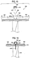
- the roof structure may be a structure as shown in Figs. 15 and 16 .
- the roof structure 500 shown in Figs. 15 and 16 includes face members 502 having end edge portions 504, an anchor clip 506, a sealing member 508, and a joint covering member 510.
- the sealingmember 508 is integrally attached on an inner surface of the joint covering member 510.
- the sealing member 508 is made of a mixture of an EPDM (ethylene-propylene terpolymer) foamed material and a butyl rubber.
- An adhesive material 512 made of a butyl rubber is attached on the lower side of the joint covering member 510.
- the anchor clip 506 is inserted into a gap between the end edge portions 504 so as to fit with constrained portions 504a of the end edge portions 504.
- Fig. 16 shows an assembled state of the roof structure 500.
- the face members 502 are disposed onto the roof plate 514 together with the anchor clip 506.
- the face members 502 are arranged so that the joint portion therebetween extends along a beam member 516 for supporting the roof plate 514.
- the anchor clip 506 sandwiched between the end edge portions 504 is disposed along the beam member 516 and is fixed to the beam member 516 by using a bolt 518.
- the joint cover member 510 is disposed on the joint portion between the end edge portions 504 engaging with the constrained portions 504a from the exterior acting elastic force between the end edge portions 504.
- the roof structure 500 can attain a favorable sealing performance and also prevent a degradation of the sealing performance resulting from thermal deterioration of the sealing member 508 by sunlight or deterioration of the sealing member 508 by repeated freezing and melting due to a snow coverage.
- the joint cover member covers the sealing member from the outer side to fit to between the constrained portions of the face members by operating the elastic force and therefore, the sealing member is pressed to the end edge portions of the face members, there is constituted a highly reliable waterproof structure which is difficult to leak water and also waterproof construction operation is facilitated.
- the anchor clip is covered by the joint cover and the sealingmember and therefore, water is not leaked from the screw hole of the anchor clip.
- the attaching metal piece is attached to pinch the joint cover member from the outer side, the attached object provided above the face member is attached by the attachingmetal piece and therefore, the attached object can easily be attached while ensuring the waterproof structure.
Applications Claiming Priority (4)
| Application Number | Priority Date | Filing Date | Title |
|---|---|---|---|
| JP2003188370A JP4153837B2 (ja) | 2003-06-30 | 2003-06-30 | 建物の防水構造 |
| JP2003188370 | 2003-06-30 | ||
| JP2003391020 | 2003-11-20 | ||
| JP2003391020A JP2005155032A (ja) | 2003-11-20 | 2003-11-20 | カバー材及びカバー材を用いた建物の防水構造 |
Publications (3)
| Publication Number | Publication Date |
|---|---|
| EP1493877A2 EP1493877A2 (en) | 2005-01-05 |
| EP1493877A3 EP1493877A3 (en) | 2010-09-01 |
| EP1493877B1 true EP1493877B1 (en) | 2016-05-25 |
Family
ID=33436464
Family Applications (1)
| Application Number | Title | Priority Date | Filing Date |
|---|---|---|---|
| EP04015422.1A Active EP1493877B1 (en) | 2003-06-30 | 2004-06-30 | Waterproof structure of building |
Country Status (6)
| Country | Link |
|---|---|
| US (1) | US7690166B2 (ko) |
| EP (1) | EP1493877B1 (ko) |
| KR (1) | KR101134232B1 (ko) |
| CN (1) | CN100532753C (ko) |
| AU (1) | AU2004202991A1 (ko) |
| TW (1) | TW200508465A (ko) |
Cited By (1)
| Publication number | Priority date | Publication date | Assignee | Title |
|---|---|---|---|---|
| EP4008854A1 (en) * | 2020-12-03 | 2022-06-08 | CWL Patent AB | An attachment arrangement |
Families Citing this family (6)
| Publication number | Priority date | Publication date | Assignee | Title |
|---|---|---|---|---|
| US8646228B2 (en) | 2009-03-24 | 2014-02-11 | Certainteed Corporation | Photovoltaic systems, methods for installing photovoltaic systems, and kits for installing photovoltaic systems |
| US20110036039A1 (en) * | 2009-08-13 | 2011-02-17 | Chen-Lu Wang | Combinatory board |
| CN103741892B (zh) * | 2014-01-10 | 2016-03-09 | 河南省建筑业协会 | 一种金属屋面锁扣及夹锁扣用的夹钳 |
| CN108832871A (zh) * | 2018-08-13 | 2018-11-16 | 广东汉能薄膜太阳能有限公司 | 防水构件及光伏发电系统 |
| AU2018442679A1 (en) * | 2018-09-28 | 2021-04-08 | Cc Wizard Oy | A building system and method |
| TWI758089B (zh) * | 2021-02-08 | 2022-03-11 | 廣懋材料科技股份有限公司 | 高性能抗風建築系統裝置 |
Family Cites Families (28)
| Publication number | Priority date | Publication date | Assignee | Title |
|---|---|---|---|---|
| US1963583A (en) * | 1930-12-15 | 1934-06-19 | Patrick E Tabor | Metal roofing |
| US2574937A (en) * | 1947-10-22 | 1951-11-13 | William E Sampson | Device for fastening metal roof to buildings |
| FR1112579A (fr) * | 1954-10-15 | 1956-03-15 | Perfectionnements aux couvertures métalliques | |
| US3375621A (en) * | 1967-01-06 | 1968-04-02 | Lexsuco Inc | Prefabricated foam expansion joints |
| US4139974A (en) * | 1976-09-07 | 1979-02-20 | Atlanta Metal Products, Inc. | Standing T-rib roof system |
| US4271651A (en) * | 1979-06-01 | 1981-06-09 | Mm Systems Corporation | Batten and paneling system |
| US4351140A (en) * | 1980-09-19 | 1982-09-28 | The Wickes Corporation | End lap seam construction for standing seam roof panels |
| US4400924A (en) * | 1980-10-21 | 1983-08-30 | Andrews Charles F | Metal roofing system |
| JPS58190528U (ja) | 1981-11-05 | 1983-12-17 | 吉兼 正男 | 組立式折板屋根 |
| JPS5919717U (ja) | 1982-07-27 | 1984-02-06 | 金田 五郎 | 笠木材 |
| CA1206719A (en) * | 1984-05-08 | 1986-07-02 | Minialoff, Edward P. | Panel and gutter assembly |
| US4586301A (en) * | 1984-08-06 | 1986-05-06 | W. P. Hickman Company | Retainer clamp membrane fastening system |
| JPS6246732Y2 (ko) | 1986-08-29 | 1987-12-19 | ||
| JPH031943A (ja) | 1989-05-30 | 1991-01-08 | Eishin Kogyo Kk | 耐熱水性に優れた御影調成形体 |
| JP2940566B2 (ja) | 1991-03-13 | 1999-08-25 | 積水化学工業株式会社 | 板材と板材を接続する方法 |
| US5272849A (en) * | 1991-06-27 | 1993-12-28 | A. Zahner Sheet Metal Company | Roof covering system |
| JPH0762374B2 (ja) * | 1992-09-14 | 1995-07-05 | 元旦ビューティ工業株式会社 | 縦葺き屋根板 |
| JPH0762375B2 (ja) * | 1992-09-14 | 1995-07-05 | 元旦ビューティ工業株式会社 | 縦葺き屋根構造及びその施工法 |
| JPH06306963A (ja) * | 1993-04-23 | 1994-11-01 | Sekisui Chem Co Ltd | 外壁目地部の防水構造 |
| JP3061702B2 (ja) | 1993-06-18 | 2000-07-10 | 積水化学工業株式会社 | 建物の雨仕舞構造 |
| JPH0734609A (ja) | 1993-07-20 | 1995-02-03 | Sekisui Chem Co Ltd | 折板屋根への構造物等取付装置 |
| JP2519660B2 (ja) | 1993-08-20 | 1996-07-31 | 一郎 大本 | 止水材 |
| JPH07279393A (ja) | 1994-04-11 | 1995-10-27 | Daiwa House Ind Co Ltd | 外壁の横目地防水構造 |
| JPH08232415A (ja) | 1995-02-24 | 1996-09-10 | Sekisui Chem Co Ltd | 軒樋水はね防止構造 |
| JP3608127B2 (ja) * | 1995-12-13 | 2005-01-05 | 東邦シートフレーム株式会社 | 鋼板屋根構造 |
| US6164021A (en) * | 1998-02-06 | 2000-12-26 | Polyfoam Products, Inc. | Hip and ridge sealing and attachment system and method of using same |
| JP2001140416A (ja) | 1999-11-18 | 2001-05-22 | Sekisui Chem Co Ltd | 屋根上太陽電池モジュ−ルの取付け金具及び取付け構造並びに太陽電池モジュ−ル搭載屋根 |
| JP2001295423A (ja) | 2000-04-14 | 2001-10-26 | Sekisui Chem Co Ltd | 折板の接続固定構造 |
-
2004
- 2004-06-29 TW TW093119007A patent/TW200508465A/zh unknown
- 2004-06-30 EP EP04015422.1A patent/EP1493877B1/en active Active
- 2004-06-30 KR KR1020040049916A patent/KR101134232B1/ko active IP Right Grant
- 2004-06-30 US US10/880,324 patent/US7690166B2/en not_active Expired - Fee Related
- 2004-06-30 CN CNB2004100550188A patent/CN100532753C/zh active Active
- 2004-06-30 AU AU2004202991A patent/AU2004202991A1/en not_active Abandoned
Cited By (1)
| Publication number | Priority date | Publication date | Assignee | Title |
|---|---|---|---|---|
| EP4008854A1 (en) * | 2020-12-03 | 2022-06-08 | CWL Patent AB | An attachment arrangement |
Also Published As
| Publication number | Publication date |
|---|---|
| US20050016102A1 (en) | 2005-01-27 |
| CN100532753C (zh) | 2009-08-26 |
| AU2004202991A1 (en) | 2005-01-20 |
| EP1493877A2 (en) | 2005-01-05 |
| EP1493877A3 (en) | 2010-09-01 |
| KR101134232B1 (ko) | 2012-04-09 |
| TW200508465A (en) | 2005-03-01 |
| US7690166B2 (en) | 2010-04-06 |
| CN1576494A (zh) | 2005-02-09 |
| KR20050002636A (ko) | 2005-01-07 |
Similar Documents
| Publication | Publication Date | Title |
|---|---|---|
| US9450534B2 (en) | Protective covering for roof mounted systems | |
| US4860511A (en) | Standing seam roof skylight systems | |
| US4649680A (en) | Standing seam roof skylight | |
| CA2085499C (en) | Building panel assembly | |
| US11814846B1 (en) | Methods of forming a leakproof pitched roof section or wall with the use of solar panels | |
| US4977721A (en) | Rigid covering for roofs and supports therefor | |
| US10900232B2 (en) | Load support structure for use on roof | |
| FI87387B (fi) | Takpanel. | |
| US6079167A (en) | Continuous ridge skylight system | |
| US9127461B2 (en) | Thermal barrier about roof support structure | |
| EP1493877B1 (en) | Waterproof structure of building | |
| JP4913621B2 (ja) | 横葺き段付金属屋根部材 | |
| JPH11107472A (ja) | 太陽電池付き屋根パネルおよび屋根構造 | |
| US9187905B2 (en) | Roof or window panel to metal roofing or siding interface securement system | |
| JP2005023590A (ja) | 建物の防水構造 | |
| JP3392379B2 (ja) | 二重葺き屋根構造 | |
| JPH0433301Y2 (ko) | ||
| JP3568492B2 (ja) | 横葺型の屋根構造 | |
| CA2156478A1 (en) | Snap-on coping holddown | |
| JP2000110309A (ja) | 横葺き外装パネルの接続構造 | |
| CA1264519A (en) | Standing seam roof skylight | |
| JPS6039381Y2 (ja) | 外囲体 | |
| JPH051526Y2 (ko) | ||
| JP2513511B2 (ja) | ユニット型横葺き屋根構造及びその施工法 | |
| JPH08120841A (ja) | 内部連結型の縦葺き屋根 |
Legal Events
| Date | Code | Title | Description |
|---|---|---|---|
| PUAI | Public reference made under article 153(3) epc to a published international application that has entered the european phase |
Free format text: ORIGINAL CODE: 0009012 |
|
| AK | Designated contracting states |
Kind code of ref document: A2 Designated state(s): AT BE BG CH CY CZ DE DK EE ES FI FR GB GR HU IE IT LI LU MC NL PL PT RO SE SI SK TR |
|
| AX | Request for extension of the european patent |
Extension state: AL HR LT LV MK |
|
| PUAL | Search report despatched |
Free format text: ORIGINAL CODE: 0009013 |
|
| AK | Designated contracting states |
Kind code of ref document: A3 Designated state(s): AT BE BG CH CY CZ DE DK EE ES FI FR GB GR HU IE IT LI LU MC NL PL PT RO SE SI SK TR |
|
| AX | Request for extension of the european patent |
Extension state: AL HR LT LV MK |
|
| 17P | Request for examination filed |
Effective date: 20110121 |
|
| 17Q | First examination report despatched |
Effective date: 20110223 |
|
| AKX | Designation fees paid |
Designated state(s): DE FR GB |
|
| GRAP | Despatch of communication of intention to grant a patent |
Free format text: ORIGINAL CODE: EPIDOSNIGR1 |
|
| INTG | Intention to grant announced |
Effective date: 20151211 |
|
| GRAS | Grant fee paid |
Free format text: ORIGINAL CODE: EPIDOSNIGR3 |
|
| GRAA | (expected) grant |
Free format text: ORIGINAL CODE: 0009210 |
|
| AK | Designated contracting states |
Kind code of ref document: B1 Designated state(s): DE FR GB |
|
| REG | Reference to a national code |
Ref country code: GB Ref legal event code: FG4D |
|
| REG | Reference to a national code |
Ref country code: DE Ref legal event code: R096 Ref document number: 602004049351 Country of ref document: DE |
|
| REG | Reference to a national code |
Ref country code: FR Ref legal event code: PLFP Year of fee payment: 13 |
|
| REG | Reference to a national code |
Ref country code: DE Ref legal event code: R097 Ref document number: 602004049351 Country of ref document: DE |
|
| PLBE | No opposition filed within time limit |
Free format text: ORIGINAL CODE: 0009261 |
|
| STAA | Information on the status of an ep patent application or granted ep patent |
Free format text: STATUS: NO OPPOSITION FILED WITHIN TIME LIMIT |
|
| 26N | No opposition filed |
Effective date: 20170228 |
|
| REG | Reference to a national code |
Ref country code: FR Ref legal event code: PLFP Year of fee payment: 14 |
|
| REG | Reference to a national code |
Ref country code: FR Ref legal event code: PLFP Year of fee payment: 15 |
|
| PGFP | Annual fee paid to national office [announced via postgrant information from national office to epo] |
Ref country code: GB Payment date: 20220512 Year of fee payment: 19 Ref country code: FR Payment date: 20220510 Year of fee payment: 19 Ref country code: DE Payment date: 20220505 Year of fee payment: 19 |
|
| REG | Reference to a national code |
Ref country code: DE Ref legal event code: R119 Ref document number: 602004049351 Country of ref document: DE |
|
| GBPC | Gb: european patent ceased through non-payment of renewal fee |
Effective date: 20230630 |