EP1493569B1 - Tete d'injection de liquide - Google Patents
Tete d'injection de liquide Download PDFInfo
- Publication number
- EP1493569B1 EP1493569B1 EP03745991A EP03745991A EP1493569B1 EP 1493569 B1 EP1493569 B1 EP 1493569B1 EP 03745991 A EP03745991 A EP 03745991A EP 03745991 A EP03745991 A EP 03745991A EP 1493569 B1 EP1493569 B1 EP 1493569B1
- Authority
- EP
- European Patent Office
- Prior art keywords
- liquid
- piezoelectric layer
- generating portion
- pressure chamber
- pressure generating
- Prior art date
- Legal status (The legal status is an assumption and is not a legal conclusion. Google has not performed a legal analysis and makes no representation as to the accuracy of the status listed.)
- Expired - Lifetime
Links
- 239000007788 liquid Substances 0.000 title claims abstract description 55
- 238000002347 injection Methods 0.000 title 1
- 239000007924 injection Substances 0.000 title 1
- 238000004891 communication Methods 0.000 claims description 32
- 239000010410 layer Substances 0.000 description 42
- 230000015572 biosynthetic process Effects 0.000 description 24
- 239000000758 substrate Substances 0.000 description 24
- 238000004519 manufacturing process Methods 0.000 description 9
- 239000000919 ceramic Substances 0.000 description 8
- 239000000463 material Substances 0.000 description 8
- 230000005684 electric field Effects 0.000 description 7
- 239000004973 liquid crystal related substance Substances 0.000 description 6
- 230000005499 meniscus Effects 0.000 description 5
- 239000002243 precursor Substances 0.000 description 5
- 238000004040 coloring Methods 0.000 description 4
- 238000005520 cutting process Methods 0.000 description 3
- 238000006073 displacement reaction Methods 0.000 description 3
- 238000004904 shortening Methods 0.000 description 3
- MCMNRKCIXSYSNV-UHFFFAOYSA-N Zirconium dioxide Chemical compound O=[Zr]=O MCMNRKCIXSYSNV-UHFFFAOYSA-N 0.000 description 2
- 239000000853 adhesive Substances 0.000 description 2
- 230000001070 adhesive effect Effects 0.000 description 2
- 230000008602 contraction Effects 0.000 description 2
- 230000000694 effects Effects 0.000 description 2
- 229910052451 lead zirconate titanate Inorganic materials 0.000 description 2
- 229910052751 metal Inorganic materials 0.000 description 2
- 239000002184 metal Substances 0.000 description 2
- 238000005192 partition Methods 0.000 description 2
- BASFCYQUMIYNBI-UHFFFAOYSA-N platinum Chemical compound [Pt] BASFCYQUMIYNBI-UHFFFAOYSA-N 0.000 description 2
- 239000002356 single layer Substances 0.000 description 2
- 238000005245 sintering Methods 0.000 description 2
- PNEYBMLMFCGWSK-UHFFFAOYSA-N aluminium oxide Inorganic materials [O-2].[O-2].[O-2].[Al+3].[Al+3] PNEYBMLMFCGWSK-UHFFFAOYSA-N 0.000 description 1
- 239000004020 conductor Substances 0.000 description 1
- 238000010276 construction Methods 0.000 description 1
- 230000006866 deterioration Effects 0.000 description 1
- 230000003292 diminished effect Effects 0.000 description 1
- 230000003467 diminishing effect Effects 0.000 description 1
- PCHJSUWPFVWCPO-UHFFFAOYSA-N gold Chemical compound [Au] PCHJSUWPFVWCPO-UHFFFAOYSA-N 0.000 description 1
- 239000010931 gold Substances 0.000 description 1
- 229910052737 gold Inorganic materials 0.000 description 1
- 238000005304 joining Methods 0.000 description 1
- HFGPZNIAWCZYJU-UHFFFAOYSA-N lead zirconate titanate Chemical compound [O-2].[O-2].[O-2].[O-2].[O-2].[Ti+4].[Zr+4].[Pb+2] HFGPZNIAWCZYJU-UHFFFAOYSA-N 0.000 description 1
- 238000003754 machining Methods 0.000 description 1
- 239000002075 main ingredient Substances 0.000 description 1
- 239000011159 matrix material Substances 0.000 description 1
- 229910001092 metal group alloy Inorganic materials 0.000 description 1
- 239000000203 mixture Substances 0.000 description 1
- 230000010355 oscillation Effects 0.000 description 1
- 239000011295 pitch Substances 0.000 description 1
- 229910052697 platinum Inorganic materials 0.000 description 1
- 230000010287 polarization Effects 0.000 description 1
- 238000003825 pressing Methods 0.000 description 1
- 238000004080 punching Methods 0.000 description 1
- 239000002994 raw material Substances 0.000 description 1
- 238000001454 recorded image Methods 0.000 description 1
- 238000007789 sealing Methods 0.000 description 1
- 238000000638 solvent extraction Methods 0.000 description 1
- 239000010935 stainless steel Substances 0.000 description 1
- 229910001220 stainless steel Inorganic materials 0.000 description 1
- 239000000126 substance Substances 0.000 description 1
Images


Classifications
-
- B—PERFORMING OPERATIONS; TRANSPORTING
- B41—PRINTING; LINING MACHINES; TYPEWRITERS; STAMPS
- B41J—TYPEWRITERS; SELECTIVE PRINTING MECHANISMS, i.e. MECHANISMS PRINTING OTHERWISE THAN FROM A FORME; CORRECTION OF TYPOGRAPHICAL ERRORS
- B41J2/00—Typewriters or selective printing mechanisms characterised by the printing or marking process for which they are designed
- B41J2/005—Typewriters or selective printing mechanisms characterised by the printing or marking process for which they are designed characterised by bringing liquid or particles selectively into contact with a printing material
- B41J2/01—Ink jet
- B41J2/135—Nozzles
- B41J2/14—Structure thereof only for on-demand ink jet heads
- B41J2/14201—Structure of print heads with piezoelectric elements
- B41J2/14233—Structure of print heads with piezoelectric elements of film type, deformed by bending and disposed on a diaphragm
-
- B—PERFORMING OPERATIONS; TRANSPORTING
- B41—PRINTING; LINING MACHINES; TYPEWRITERS; STAMPS
- B41J—TYPEWRITERS; SELECTIVE PRINTING MECHANISMS, i.e. MECHANISMS PRINTING OTHERWISE THAN FROM A FORME; CORRECTION OF TYPOGRAPHICAL ERRORS
- B41J2/00—Typewriters or selective printing mechanisms characterised by the printing or marking process for which they are designed
- B41J2/005—Typewriters or selective printing mechanisms characterised by the printing or marking process for which they are designed characterised by bringing liquid or particles selectively into contact with a printing material
- B41J2/01—Ink jet
- B41J2/135—Nozzles
- B41J2/14—Structure thereof only for on-demand ink jet heads
- B41J2/14201—Structure of print heads with piezoelectric elements
-
- B—PERFORMING OPERATIONS; TRANSPORTING
- B41—PRINTING; LINING MACHINES; TYPEWRITERS; STAMPS
- B41J—TYPEWRITERS; SELECTIVE PRINTING MECHANISMS, i.e. MECHANISMS PRINTING OTHERWISE THAN FROM A FORME; CORRECTION OF TYPOGRAPHICAL ERRORS
- B41J2/00—Typewriters or selective printing mechanisms characterised by the printing or marking process for which they are designed
- B41J2/005—Typewriters or selective printing mechanisms characterised by the printing or marking process for which they are designed characterised by bringing liquid or particles selectively into contact with a printing material
- B41J2/01—Ink jet
- B41J2/135—Nozzles
- B41J2/16—Production of nozzles
- B41J2/1607—Production of print heads with piezoelectric elements
- B41J2/161—Production of print heads with piezoelectric elements of film type, deformed by bending and disposed on a diaphragm
-
- B—PERFORMING OPERATIONS; TRANSPORTING
- B41—PRINTING; LINING MACHINES; TYPEWRITERS; STAMPS
- B41J—TYPEWRITERS; SELECTIVE PRINTING MECHANISMS, i.e. MECHANISMS PRINTING OTHERWISE THAN FROM A FORME; CORRECTION OF TYPOGRAPHICAL ERRORS
- B41J2/00—Typewriters or selective printing mechanisms characterised by the printing or marking process for which they are designed
- B41J2/005—Typewriters or selective printing mechanisms characterised by the printing or marking process for which they are designed characterised by bringing liquid or particles selectively into contact with a printing material
- B41J2/01—Ink jet
- B41J2/135—Nozzles
- B41J2/14—Structure thereof only for on-demand ink jet heads
- B41J2/14201—Structure of print heads with piezoelectric elements
- B41J2/14233—Structure of print heads with piezoelectric elements of film type, deformed by bending and disposed on a diaphragm
- B41J2002/14258—Multi layer thin film type piezoelectric element
-
- B—PERFORMING OPERATIONS; TRANSPORTING
- B41—PRINTING; LINING MACHINES; TYPEWRITERS; STAMPS
- B41J—TYPEWRITERS; SELECTIVE PRINTING MECHANISMS, i.e. MECHANISMS PRINTING OTHERWISE THAN FROM A FORME; CORRECTION OF TYPOGRAPHICAL ERRORS
- B41J2/00—Typewriters or selective printing mechanisms characterised by the printing or marking process for which they are designed
- B41J2/005—Typewriters or selective printing mechanisms characterised by the printing or marking process for which they are designed characterised by bringing liquid or particles selectively into contact with a printing material
- B41J2/01—Ink jet
- B41J2/135—Nozzles
- B41J2/14—Structure thereof only for on-demand ink jet heads
- B41J2002/14419—Manifold
Definitions
- the invention relates to a liquid ejection head which causes pressure fluctuations in liquid stored in a pressure chamber by distortion of a piezoelectric vibrator, thereby ejecting the liquid from a nozzle orifice in the form of a droplet.
- a liquid ejection head which ejects liquid from a nozzle orifice in the form of a droplet by causing a pressure fluctuation in the liquid stored in a pressure chamber, includes a recording head, a liquid crystal ejection head, and a coloring material ejection head, for example.
- the recording head is to be provided in an image recording apparatus such as a printer or a plotter and ejects liquid ink in the form of ink droplets.
- the liquid crystal ejection head is to be used with a display manufacturing system for manufacturing a liquid crystal display.
- liquid crystal which has been ejected from a liquid crystal ejection head and assumes the form of a droplet is ejected toward a predetermined grid of a display substrate having a plurality of grids.
- the coloring material ejection head is to be used with a filter manufacturing system for manufacturing a color filter and ejects a coloring material on the surface of a filter substrate.
- Such a liquid ejection head comes in various types.
- One type of such a liquid ejection heads ejects a droplet by flexural deformation of a piezoelectric vibrator formed on the surface of a vibration plate.
- the liquid ejection head comprises an actuator unit having, e.g., a pressure chamber and a piezoelectric vibrator; and a channel unit having nozzle orifices and a common liquid chamber.
- the liquid ejection head varies the volume of the pressure chamber by deforming the piezoelectric vibrator, which is provided on a vibration plate, thereby causing pressure fluctuations in the liquid stored in the pressure chamber.
- a droplet is ejected from the nozzle orifice. For instance, liquid is compressed by contraction of the pressure chamber, thereby squeezing the liquid out of the nozzle orifice.
- the above piezoelectric vibrator has a single-layer structure comprising: a piezoelectric layer; a drive electrode formed on one surface of the piezoelectric layer and electrically connected to a supply source of a drive signal; and a common electrode formed on the other surface of the piezoelectric layer. Since the size of the piezoelectric vibrator is determined in accordance with an area of the pressure chamber, the deformable amount of the piezoelectric vibrator in the liquid ejection head is approximately 0.11 ⁇ m at most.
- the voltage applied between the electrodes is increased to increase the deformed amount of the piezoelectric vibrator, the stress is concentrated to the joining face of the piezoelectric vibrator and the vibration plate, so that the piezoelectric layer is peeled off the vibration plate.
- the thickness of the piezoelectric vibrator may be increased.
- it is impractical because more time would be necessary for fabricating such a thick piezoelectric vibrator, thereby increasing costs.
- EP-A-1 024 003 discloses an inkjet head where the inertance of the nozzle, the ink supply channel and the pressure generating element of the head is discussed and how the oscillation frequency of ink in a pressure chamber is a function of said inertances.
- pressure vibrations of the natural period Tc arise in the liquid, for reasons of fluctuation of the volume of the pressure chamber.
- a meniscus (free surface of liquid exposed in a nozzle orifice) also vibrates at the natural period Tc.
- the meniscus reciprocally moves between an ejecting direction and a direction toward the pressure chamber.
- the quantity of a droplet to be ejected and the flight velocity of the droplet vary in accordance with the state of the meniscus (i.e., the position and moving direction of the meniscus) achieved when the pressure chamber contracts and expands.
- the state of the meniscus achieved at the time of contraction and expansion of the pressure chamber must be made uniform.
- the timing at which the droplets are to be ejected is defined as "n" times the natural period Tc. Shortening the natural period Tc is indispensable for effecting high-frequency ejection of a droplet.
- the invention has been conceived in view of the circumstances and aims at providing a liquid ejection head capable of ejecting a droplet at a higher frequency.
- a liquid ejection head will be described by taking, as an example, an inkjet recording head (hereinafter referred to as a "recording head") to be provided on an image recording apparatus such as a printer or a plotter.
- the recording head is essentially constituted of a channel unit 2, an actuator unit 3, and a film-shaped wiring board 4.
- a plurality of actuator units 3 are arranged side by side on and joined to the surface of the channel unit 2.
- the wiring board 4 is provided on the other surface of the actuator units 3 opposite the surface having the channel unit 2 provided thereon.
- the channel unit 2 is fabricated from a supply port formation substrate 7 in which are formed an ink supply port 5 (a liquid supply port according to the invention) and through holes to constitute portions of nozzle communication ports 6; an ink chamber formation substrate 9 in which are formed through holes to act as a common ink chamber 8 and through holes to constitute a portion of the nozzle communication port 6; and a nozzle plate 11 in which are formed nozzle orifices 10 in a secondary scanning direction.
- the supply port formation substrate 7, the ink chamber formation substrate 9, and the nozzle plate 11 are formed by pressing, for example, a stainless steel plate.
- the supply port formation substrate 7 assumes a thickness of 100 ⁇ m
- the ink chamber formation substrate 9 assumes a thickness of 150 ⁇ m
- the nozzle plate 11 assumes a thickness of 80 ⁇ m.
- the drawings show a portion of the channel unit 2. Specifically, the portion corresponds to one actuator unit 3.
- three actuator units 3 are joined to one channel unit 2.
- the ink supply port 5, the nozzle communication port 6, the supply port formation substrate 7, the common ink chamber 8, and the like are formed for each actuator unit. Hence, they are provided in a total of three sets.
- the channel unit 2 is fabricated by placing the nozzle plate 11 on one surface of the ink chamber formation substrate 9 (e.g., a lower surface in the drawing) and the supply port formation substrate 7 on the other surface of the same (e.g., an upper surface in the drawing), and bonding together the supply port formation substrate 7, the ink chamber formation substrate 9, and the nozzle plate 11.
- the channel unit 2 is fabricated by bonding together the members 7, 9, and 11 by use of, e.g., a sheet-shaped adhesive.
- the nozzle orifice 10 is a circular passage having a very small diameter.
- the nozzle orifice is a tapered passage which becomes smaller in diameter toward a nozzle surface (i.e., the exterior surface of the nozzle plate 11).
- a nozzle surface i.e., the exterior surface of the nozzle plate 11.
- an external opening of the nozzle orifice 10 facing the nozzle surface assumes a diameter of 20 ⁇ m, and the length of the passage is identical with the thickness of the nozzle plate 11; that is, 80 ⁇ m.
- the nozzle orifice has a cone angle of 35 degrees.
- the nozzle orifices 10 are formed in a plurality of rows at predetermined pitches. Rows of nozzles 12 are formed from the plurality of nozzle orifices 10 arranged in rows. For example, a row of nozzles 12 is formed from 92 nozzle orifices 10. Two rows of nozzles 12 are formed for one actuator unit 3. Therefore, in the embodiment, a total of six rows of nozzles 12 are formed side by side for one channel unit 2.
- the ink supply port 5 is a circular passage having a very small diameter, as in the case of the nozzle orifice 10, and acts as an orifice.
- An opening of the ink supply port 5 facing the pressure chamber i.e., a feeding-side communication port
- the ink supply port 5 is a tapered passage which becomes smaller in diameter toward the common ink chamber 8.
- the external opening of the ink supply port 5 facing the common ink chamber 8 assumes a diameter of 20 ⁇ m, and the passage length of the ink supply port is identical with the thickness of the supply port formation substrate 7; that is, 100 ⁇ m.
- the ink supply port 5 assumes a cone angle of 35 degrees.
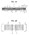
- the actuator unit 3 is also called a head chip and is a kind of piezoelectric actuator. As shown in Fig. 2A , the actuator unit 3 comprises a pressure chamber formation substrate 14 in which a through hole to constitute a pressure chamber 13 is formed; a vibration plate 15 which partitions a part of the pressure chamber 13; a cover member 17 in which are formed a through hole to constitute a supply-side communication port 16 and a through hole to constitute a portion of the nozzle communication port 6; and a piezoelectric vibrator 18.
- the pressure chamber formation substrate 14 and the cover member 17 preferably assume a thickness of 50 ⁇ m or more each, more preferably, 100 ⁇ m or more.
- the thickness of the pressure chamber formation substrate 14 is set to 80 ⁇ m, and the thickness of the cover member 17 is set to 150 ⁇ m.
- the vibration plate 15 preferably assumes a thickness of 50 ⁇ m or less, more preferably 3 to 12 ⁇ m or thereabouts. In the embodiment, the vibration plate 15 is set to a thickness of 6 ⁇ m.
- the actuator unit 3 is made by placing the cover member 17 on one surface of the pressure chamber formation substrate 14 and the vibration plate 15 on the other surface of the same, and by bonding together the members 14, 15, and 17.
- the pressure chamber formation substrate 14, the vibration plate 15, and the cover member 17 are made from ceramics, such as alumina or zirconia, and are integrated together by sintering.
- a green sheet (a sheet member which has not yet been sintered) is subjected to processing, such as cutting or punching, thereby forming required through holes.
- processing such as cutting or punching
- sheet-shaped precursors for use in forming the pressure chamber formation substrate 14, the vibration plate 15, and the cover member 17 are formed.
- the sheet-shaped precursors are laminated and sintered, thereby integrating the sheet-shaped precursors into a single ceramic sheet.
- special bonding operation is not required.
- a high sealing characteristic can also be achieved at joined surfaces between the respective sheet-shaped precursors.
- the pressure chambers 13 and the nozzle communication ports 6, which are equal in number to units, are formed in one ceramic sheet.
- a plurality of actuator units (head chips) 3 are formed from one ceramic sheet.
- a plurality of chip areas, which are to become single actuator units 3 respectively, are set in a matrix pattern within one ceramic sheet.
- the ceramic sheet is sliced for each chip area, thereby fabricating a plurality of actuator units 3.
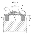
- the pressure chamber 13 is a rectangular-parallelepiped hollow section which is elongated in the direction orthogonal to the row of nozzles 12, and a plurality of pressure chambers 13 are formed so as to correspond to the nozzle orifices 10. Specifically, as shown in Fig. 2B , the pressure chambers 13 are arranged in rows aligned with the row of nozzles. As shown in Figs. 3 and 4 , the pressure chamber 13 of the embodiment has a height hc of 80 ⁇ m, a width wc of 160 ⁇ m, and a length Lc of 1.1 mm. In other words, the ratio between a height, a width, and a length is set to about 1:2:14.
- each of pressure chambers 13 is in communication with the corresponding nozzle orifice 10 by way of the nozzle communication port 6.
- the other longitudinal end of each of the pressure chambers 13 is in communication with the common ink chamber 8 by way of the supply-side communication port 16 and the ink supply port 5.
- a part of the pressure chamber 13 i.e., an upper surface thereof is partitioned by the vibration plate 15.
- the piezoelectric vibrator 18 is a piezoelectric vibrator of so-called flexural vibration mode and is provided, for each pressure chamber 13, on the surface of the vibration plate opposite the pressure chamber 13. As shown in Figs. 3 and 4 , the piezoelectric vibrator 18 assumes the form of a block which is elongated in the longitudinal direction of the pressure chamber. In the embodiment, the piezoelectric element 18 has a width substantially equal to that of the pressure chamber 13, and a length of 160 ⁇ m. Further, the piezoelectric vibrator 18 is somewhat greater in length than the pressure chamber 13, and both ends of the piezoelectric vibrator 18 are arranged so as to extend beyond longitudinal ends of the pressure chamber 13.
- the piezoelectric vibrator 18 of the embodiment is formed from a piezoelectric layer 21, a common electrode 22, and a drive electrode 23 (an individual electrode), or the like.
- the piezoelectric layer 21 is sandwiched between the common electrode 22 and the drive electrode 23.
- a supply source of a drive signal (not shown) is electrically connected to the drive electrode 23 via the individual terminal.
- the common electrode 22 is controlled to, e.g., an earth potential.
- an electric field whose intensity is related to a potential difference between the drive electrode 23 and the common electrode 22 develops.
- the piezoelectric layer 21 becomes distorted in accordance with the intensity of the imparted electric field.
- the piezoelectric layer 21 is constituted by an upper (outer) piezoelectric layer 24 and a lower (inner) piezoelectric layer 25.
- the common electrode 22 is formed from an upper common electrode (an external common electrode) 26 and a lower common electrode (an internal common electrode) 27.
- the common electrode 22 and the drive electrode 23 i.e., the individual electrode) constitute an electrode layer.
- orientations “up (external)” and “down (internal)” indicate positional relationships defined with reference to the vibration plate 15. Specifically, the term “up (external)” indicates a position distant from the vibration plate 15, and the term “down (internal)” indicates a position close to the vibration plate 15.
- the drive electrode 23 is formed along a boundary between the upper piezoelectric layer 24 and the lower piezoelectric layer 25.
- the lower common electrode 27 is formed between the lower piezoelectric layer 25 and the vibration plate 15.
- the upper common electrode 26 is formed on the surface of the upper piezoelectric layer 24 opposite the lower piezoelectric layer 25. More specifically, the piezoelectric vibrator 18 is of a multilayer structure into which the lower common electrode 27, the lower piezoelectric layer 25, the drive electrode 23, the upper piezoelectric layer 24, and the upper common electrode 26 are stacked, in this sequence from the vibration plate 15.
- the thickness of the upper piezoelectric layer 24 and that of the lower piezoelectric layer 25 are set to a value of 10 ⁇ m or less.
- the thickness of the upper piezoelectric layer 24 is set to 8 ⁇ m
- the thickness of the lower piezoelectric layer 25 is set to 9 ⁇ m.
- the total thickness of the piezoelectric layer 21 is set to 17 ⁇ m.
- the overall thickness of the piezoelectric vibrator 18, including the common electrode 22, is set to a value of about 20 ⁇ m. The thickness of the piezoelectric vibrator 18 can be set in this way, and hence required rigidity can be obtained, thereby diminishing the compliance of the vibration plate 15.
- the upper common electrode 26 and the lower common electrode 27 are controlled to a given potential regardless of the drive signal.
- the upper common electrode 26 and the lower common electrode 27 are electrically connected together and controlled to the earth potential.
- the drive electrode 23 is electrically connected to the drive signal supply source and, hence, changes a potential in accordance with a supplied drive signal. Accordingly, supply of the drive signal induces an electric field between the drive electrode 23 and the upper common electrode 26 and an electric field between the drive electrode 23 and the lower common electrode 27, wherein the electric fields are opposite in direction to each other.
- Various conductors e.g., a single metal substance, a metal alloy, or a mixture consisting of electrically insulating ceramics and metal, are selected as materials which constitute the electrodes 23, 26, and 27.
- the materials are required not to cause any deterioration at a sintering temperature.
- gold is used for the upper common electrode 26, and platinum is used for the lower common electrode 27 and the drive electrode 23.
- the upper piezoelectric layer 24 and the lower piezoelectric layer 25 are formed from piezoelectric material containing lead zirconate titanate (PZT) as the main ingredient.
- PZT lead zirconate titanate
- the direction of polarization of the upper piezoelectric layer 24 is opposite that of the lower piezoelectric layer 25. Therefore, when the drive signal is applied to the upper piezoelectric layer 24 and the lower piezoelectric layer 25, the layers expand and contract in the same direction and can become deformed without any problem.
- the upper piezoelectric layer 24 and the lower piezoelectric layer 25 deform the vibration plate 15 such that the volume of the pressure chamber 13 is reduced with an increase in the potential of the drive electrode 23 and such that the volume of the pressure chamber 13 is increased with a decrease in the potential of the drive electrode 23.
- the amount of displacement of the piezoelectric vibrator 18 stemming from supply of a drive signal is set to a value of 0.16 ⁇ m or more by use of the piezoelectric vibrator 18 of multilayer structure. In this embodiment, it is set to a value of 0.17 ⁇ m. As a result, ink droplets of quantity required to perform recording operation can be ejected from the nozzle orifice 10.
- the compliance of the piezoelectric vibrator 18 is set to a value equal to or smaller than the compliance of ink (Ci which will be described later) by use of the piezoelectric vibrator 18 of a multilayer structure. As a result, the influence of variations in compliance of the piezoelectric vibrator 18 stemming from manufacturing operation can be diminished. Ink droplets can be ejected with the pressure chambers 13 being set to a uniform flying speed and a uniform quantity.
- an electric field which is determined in accordance with an interval between the drive electrode 23 and each of the common electrodes 26, 27 (i.e., the thickness of each piezoelectric layer) and a potential difference between the drive electrode 23 and each of the common electrodes 26, 27, is applied to each of the piezoelectric layers 24, 25.
- the thickness of each of the piezoelectric layers 24, 25 can be reduced in comparison with the piezoelectric vibrator of the single layer structure in which a single piezoelectric layer is sandwiched by a drive electrode and a common electrode.
- the stress can be also reduced.
- the actuator unit 3 and the channel unit 2 are joined together.
- a sheet-shaped adhesive is interposed between the supply port formation substrate 7 and the cover member 17. In this state, pressure is applied to the actuator unit 3 toward the channel unit 2, whereupon the actuator unit 3 and the channel unit 2 are bonded together.
- the nozzle communication port 6 and the supply-side communication port 16 are formed from passages, each assuming a circular cross-sectional profile.
- the nozzle communication port 6 of the embodiment is formed from a passage which has a diameter of 125 ⁇ m and a length of 400 ⁇ m.
- the supply-side communication port 16 is formed from a passage which has a diameter of 125 ⁇ m and a length of 150 ⁇ m.
- a string of ink flow passages are formed for each nozzle orifice 10 so as to extend from the common ink chamber 8 to the nozzle orifice 10 by way of the ink supply port 5, the supply-side communication port 16, the pressure chamber 13, and the nozzle communication port 6.
- the inside of each ink flow passage is filled with ink.
- a corresponding pressure chamber 13 expands or contracts by deforming the piezoelectric vibrator 18, thereby causing pressure fluctuations in the ink stored in the pressure chamber 13.
- the nozzle orifice 10 can eject an ink droplet. For instance, if the pressure chamber 13 having a fixed volume is once expanded to fill the pressure chamber 13 with ink.
- the pressure chamber 13 is rapidly contracted to eject an ink droplet.
- new ink is supplied into the ink flow passage from the common ink chamber 8, so that ink droplets can be ejected continuously.
- the natural period Tc of the ink stored in the pressure chamber 13 must be set as small as possible.
- the natural period Tc can be expressed by Equation 1.
- Tc 2 ⁇ ⁇ ⁇ Ci + Cv ⁇ Mn + M Mc / 2 ⁇ Ms + Mc / 2 / Mn + Ms + Mc
- Ci denotes compliance of the ink stored in the pressure generating portion
- Cv denotes rigidity compliance of the pressure chamber formation substrate 14
- Mn denotes the inertance of the nozzle orifice 10
- Ms denotes the inertance of the ink supply port 5
- Mc denotes the inertance of the pressure generating portion.
- the pressure generating portion is constituted by hollow sections formed between the nozzle orifice 10 and the ink supply port 5.
- the pressure generating portion is constituted by hollow sections including the pressure chamber 13, the nozzle communication port 6, and the supply-side communication port 16. Since the pressure chamber 13, the nozzle communication port 6, and the supply-side communication port 16 are substantially equal in cross sectional area, the inertance Mc of the pressure generating portion can be expressed by Equation 2. Mc ⁇ ⁇ Lc / Sc where ⁇ denotes the density of ink; Lc denotes the length of the pressure chamber 13; and Sc denotes the cross section of the pressure chamber 13.
- the inertance Ms of the ink supply port 5 can be expressed by Equation 3.
- Ms ⁇ ⁇ Ls / Ss where ⁇ denotes the density of ink; Ls denotes the length of the ink supply port 5; and Ss denotes the cross section of the ink supply, port 5.
- Mn of the nozzle orifice 10 can be expressed by Equation 4. Mn ⁇ ⁇ Ln / Sn where ⁇ denotes the density of ink; Ln denotes the length of the nozzle orifice 10; and Sn denotes the cross section of the nozzle orifice 10.
- the thickness of each substrate is essentially limited to a predetermined thickness.
- the length of the supply-side communication port 6 and that of the nozzle communication port 16 assume a substantially constant value.
- the inertance Mc of the pressure generating portion is substantially dominated by the length Lc of the pressure chamber 13.
- the rigidity compliance Cv of the pressure chamber formation substrate 14 is an element for dominantly defining the compliance of the pressure chamber 13.
- the rigidity compliance Cv is a volume change ⁇ V with respect to a pressure change ⁇ P and hence can be expressed as Equation (5).
- Cv ⁇ V / ⁇ P
- the rigidity compliance Cv is set to become equal to or less than the compliance Ci of the ink.
- the proportion of the compliance Ci of the ink accounting for the compliance of the pressure chamber 13 becomes relatively greater than the proportion of the rigidity compliance Cv. Therefore, variations in the machining precision of a pressure chamber constituting member, such as a partition partitioning adjacent pressure chambers 13 and the vibration plate 15, become less likely to affect the ejection characteristic of an ink droplet.
- the inertance Mn of the nozzle orifice 10 and the inertance Ms of the ink supply port 5 are set so as to become greater than the inertance Mc of the pressure generating portion.
- the length Lc of the pressure chamber 13 is made as small as possible, and the inertance Mc of the pressure generating portion is made so as to become smaller than the inertance Mn of the nozzle orifice 10 and the inertance Ms of the ink supply port 5.
- the inertance Mc has become small, the compliance Ci of ink and the rigidity compliance Cv change in direct proportion to the length Lc of the pressure chamber 13.
- the compliance Ci of the ink and the rigidity compliance Cv also become smaller. Consequently, the natural period Tc can be shortened.
- Another measure for increasing the cross section Sc of the pressure chamber 13 so as to become larger than that achieved hitherto is also conceivable for reducing the inertance Mc. In this case, the compliance Ci of the ink and the rigidity compliance Cv also become greater, and hence the natural period Tc cannot be shortened.
- the diameter of the nozzle orifice 10 is set to a value smaller than the conventional value (e.g., 25 ⁇ m); that is, 20 ⁇ m, thereby increasing the inertance Mn of the nozzle orifice 10. Hence, an ink droplet can be ejected at high speed.
- the inertance Mn of the nozzle orifice 10 and the inertance Ms of the ink supply port 5 are each set to a value which is double or more the inertance Mc of the pressure generating portion. The reason for this is that the influence of the natural period Tc due to the pressure generating portion is made ineffective without fail.
- the length of the pressure chamber 13 is set such that relationships, that is, Mn ⁇ 2Mc and Ms ⁇ 2Mc; more specifically, the length of the pressure chamber 13 is set to a length of 1.1 mm or less, the natural period Tc is defined in terms of the inertance Mn of the nozzle orifice 10 and the inertance Ms of the ink supply port 5.
- the inertance Mc is reduced by shortening the length Lc of the pressure chamber 13. Hence, the amount of displacement (distortion) of the piezoelectric vibrator 18 is reduced correspondingly.
- the piezoelectric vibrator 18 of a multilayer structure is used in the embodiment in the manner as mentioned previously, thereby increasing the force developing in the piezoelectric vibrator 18. Even in this regard, an ink droplet of very small quantity (e.g., an ink droplet of 3 pL to 6 pL) can be ejected at high speed.
- the natural period Tc can be shortened to a value of 7 ⁇ s or less (6.5 ⁇ s in the embodiment).
- an ink droplet of 6 pL or more can be ejected at a frequency of 50 kHz or higher.
- an ink droplet of 3 pL or less can be ejected at a frequency of 30 kHz or higher.
- the quantity of one ink droplet can be made smaller than that of a conventional ink droplet.
- a frequency at which an ink droplet is to be ejected can be made higher than a conventional frequency, and hence high image quality of a recorded image and high-speed recording can be achieved simultaneously at a higher level.
- the length of the pressure chamber 13 can be shortened when compared with the length of a conventional pressure chamber, cost reduction can also be attempted. Specifically, the length of the pressure chamber 13 is shorter than that of a conventional pressure chamber, and hence the number of actuator units 3 which can be laid out in one ceramic sheet can be increased. Hence, the actuator units 3 can be manufactured in greater number than those manufactured conventionally even by employment of the same manufacturing process (i.e., the same operations). The actuator units 3, can be manufactured from the same quantity of raw material in greater number than those manufactured conventionally. As mentioned above, an attempt can be made to improve a manufacturing efficiency and saving of material costs, and hence cost-cutting of the recording head 1 can be realized.
- the invention has been described by taking the recording head 1 as an example of the liquid ejection head. However, the invention can also be applied to another liquid ejection head, such as a liquid-crystal ejection head or a coloring material ejection head.
Landscapes
- Particle Formation And Scattering Control In Inkjet Printers (AREA)
- Fuel-Injection Apparatus (AREA)
Claims (10)
- Tête d'éjection de liquide, comprenant :une chambre de liquide (8) ;un orifice de buse (10) ;une partie de génération de pression (13), prévue dans un canal de liquide communiquant avec la chambre de liquide et l'orifice de buse ;un vibrateur piézoélectrique (18), prévu afin de faire varier le volume de la partie de génération de pression afin que le liquide situé dans la partie de génération de pression soit éjecté de l'orifice de buse comme une gouttelette de liquide en déformant le vibrateur ; etun port d'alimentation en liquide (16), disposé entre la chambre de liquide et la partie de génération de pression afin de servir d'orifice, caractérisée en ce quele vibrateur piézoélectrique possède une structure multicouches qui comprend :dans laquelle la première électrode commune et la seconde électrode commune sont électriquement reliées à un potentiel commun ;une première électrode commune (27) ;une première couche piézoélectrique (25) formée sur la première électrode commune ;une électrode de commande (23), formée sur la première couche piézoélectrique, et électriquement reliée à une source d'alimentation d'un signal de commande ;une seconde couche piézoélectrique (24) formée sur l'électrode de commande ; etune seconde électrode commune (26), formée sur la seconde couche piézoélectrique ; et
dans laquelle une inertance de l'orifice de buse et une inertance du port d'alimentation en liquide sont supérieures à une inertance de la partie de génération de pression. - Tête d'éjection de liquide selon la revendication 1, dans laquelle une épaisseur de la seconde couche piézoélectrique et une épaisseur de la première couche piézoélectrique sont de 10 µm ou moins.
- Tête d'éjection de liquide selon la revendication 1 ou 2, dans laquelle l'inertance de l'orifice de buse et l'inertance du port d'alimentation en liquide sont chacune définies de façon à être supérieures à 2 fois l'inertance de la partie de génération de pression.
- Tête d'éjection de liquide selon l'une quelconque des revendications 1 à 3, dans laquelle la partie de génération de pression comprend :une chambre de pression allongée (13), dont un volume est variable par la déformation du vibrateur ;un port de communication avec la buse (6), communiquant avec une extrémité longitudinale de la chambre de pression et l'orifice de buse ; etun port de communication avec le côté alimentation (16), communiquant avec l'autre extrémité longitudinale de la chambre de pression et le port d'alimentation en liquide ; etdans laquelle une longueur de la chambre de pression est de 1,1 mm ou moins.
- Tête d'éjection de liquide selon l'une quelconque des revendications 1 à 4, dans laquelle une quantité de déformation du vibrateur piézoélectrique est de 0,16 µm ou plus.
- Tête d'éjection de liquide selon l'une quelconque des revendications 1 à 5, dans laquelle une élasticité du vibrateur piézoélectrique est définie selon une élasticité du liquide ou moins.
- Tête d'éjection de liquide selon l'une quelconque des revendications 1 à 6, dans laquelle un volume de la gouttelette de liquide éjectée par l'orifice de buse est de 6 pL ou plus, et une fréquence d'éjection de la gouttelette de liquide est de 50 kHz ou plus.
- Tête d'éjection de liquide selon l'une quelconque des revendications 1 à 6, dans laquelle un volume de la gouttelette de liquide éjectée par l'orifice de buse est de 3 pL ou moins, et une fréquence d'éjection de la gouttelette de liquide est de 30 kHz ou plus.
- Tête d'éjection de liquide selon l'une quelconque des revendications 1 à 8, dans laquelle une période naturelle de la partie de génération de pression est de 7 µs ou moins.
- Tête d'éjection de liquide selon l'une quelconque des revendications précédentes, comprenant une plaque de vibration (15), qui définit une partie de la partie de génération de pression, dans laquelle le vibrateur piézoélectrique est prévu sur une surface de la plaque de vibration qui est opposée à une surface tournée vers la partie de génération de pression, la plaque de vibration étant agencée afin que le volume de la partie de génération de pression soit varié pour éjecter du liquide dans la partie de génération de pression depuis l'orifice de buse ou une gouttelette de liquide en déformant la plaque de vibration en déformant le vibrateur.
Priority Applications (1)
| Application Number | Priority Date | Filing Date | Title |
|---|---|---|---|
| EP08171066A EP2047995B1 (fr) | 2002-04-09 | 2003-04-09 | Tête d'éjection de liquide |
Applications Claiming Priority (3)
| Application Number | Priority Date | Filing Date | Title |
|---|---|---|---|
| JP2002106567 | 2002-04-09 | ||
| JP2002106567 | 2002-04-09 | ||
| PCT/JP2003/004535 WO2003084758A1 (fr) | 2002-04-09 | 2003-04-09 | Tete d'injection de liquide |
Related Child Applications (1)
| Application Number | Title | Priority Date | Filing Date |
|---|---|---|---|
| EP08171066A Division EP2047995B1 (fr) | 2002-04-09 | 2003-04-09 | Tête d'éjection de liquide |
Publications (3)
| Publication Number | Publication Date |
|---|---|
| EP1493569A1 EP1493569A1 (fr) | 2005-01-05 |
| EP1493569A4 EP1493569A4 (fr) | 2008-02-13 |
| EP1493569B1 true EP1493569B1 (fr) | 2009-07-08 |
Family
ID=28786432
Family Applications (2)
| Application Number | Title | Priority Date | Filing Date |
|---|---|---|---|
| EP08171066A Expired - Fee Related EP2047995B1 (fr) | 2002-04-09 | 2003-04-09 | Tête d'éjection de liquide |
| EP03745991A Expired - Lifetime EP1493569B1 (fr) | 2002-04-09 | 2003-04-09 | Tete d'injection de liquide |
Family Applications Before (1)
| Application Number | Title | Priority Date | Filing Date |
|---|---|---|---|
| EP08171066A Expired - Fee Related EP2047995B1 (fr) | 2002-04-09 | 2003-04-09 | Tête d'éjection de liquide |
Country Status (7)
| Country | Link |
|---|---|
| US (7) | US7140554B2 (fr) |
| EP (2) | EP2047995B1 (fr) |
| JP (2) | JP4604490B2 (fr) |
| CN (2) | CN101054020B (fr) |
| AT (1) | ATE435749T1 (fr) |
| DE (2) | DE60332569D1 (fr) |
| WO (1) | WO2003084758A1 (fr) |
Families Citing this family (18)
| Publication number | Priority date | Publication date | Assignee | Title |
|---|---|---|---|---|
| US7140554B2 (en) | 2002-04-09 | 2006-11-28 | Seiko Epson Corporation | Liquid ejection head |
| US20050068379A1 (en) * | 2003-09-30 | 2005-03-31 | Fuji Photo Film Co., Ltd. | Droplet discharge head and inkjet recording apparatus |
| EP1707369B1 (fr) * | 2005-03-30 | 2011-03-23 | Brother Kogyo Kabushiki Kaisha | Appareil de transport de liquide et procédé pour la production de l'appareil de transport de liquide |
| KR100694132B1 (ko) * | 2005-06-28 | 2007-03-12 | 삼성전자주식회사 | 잉크 카트리지의 잉크 채널 유닛과 그 제조 방법 |
| US7722165B2 (en) * | 2005-12-07 | 2010-05-25 | Brother Kogyo Kabushiki Kaisha | Liquid-droplet jetting apparatus |
| EP2006111B1 (fr) * | 2006-03-29 | 2014-02-26 | Kyocera Corporation | Dispositif de distribution de liquide |
| GB0606685D0 (en) * | 2006-04-03 | 2006-05-10 | Xaar Technology Ltd | Droplet Deposition Apparatus |
| EP2140507B1 (fr) * | 2007-03-27 | 2014-02-26 | Kyocera Corporation | Elément piézoélectrique multicouche et son procédé de production |
| JP5100243B2 (ja) * | 2007-08-07 | 2012-12-19 | キヤノン株式会社 | 液体吐出ヘッド |
| JP2009045786A (ja) * | 2007-08-17 | 2009-03-05 | Seiko Epson Corp | 液体噴射ヘッドおよびその製造方法 |
| JP4662084B2 (ja) * | 2008-07-25 | 2011-03-30 | セイコーエプソン株式会社 | 液体吐出ヘッドおよび液体噴射装置 |
| WO2010089822A1 (fr) * | 2009-02-09 | 2010-08-12 | 株式会社村田製作所 | Organe d'atomisation et atomiseur équipé de celui-ci |
| US8177338B2 (en) * | 2009-12-10 | 2012-05-15 | Xerox Corporation | High frequency mechanically actuated inkjet |
| US9067221B2 (en) * | 2013-03-29 | 2015-06-30 | Bowles Fluidics Corporation | Cup-shaped nozzle assembly with integral filter structure |
| EP2716460B1 (fr) * | 2011-05-28 | 2019-07-03 | Kyocera Corporation | Tête de sortie de liquide et dispositif d'enregistrement utilisant celle-ci |
| JP6136217B2 (ja) * | 2011-12-27 | 2017-05-31 | 株式会社リコー | 通信管理システム、通信システム、プログラム、及びメンテナンスシステム |
| JP5983252B2 (ja) * | 2012-09-28 | 2016-08-31 | ブラザー工業株式会社 | 液体吐出装置、基板の接続構造、及び、液体吐出装置の製造方法 |
| JP2018069715A (ja) * | 2016-11-04 | 2018-05-10 | セイコーエプソン株式会社 | 印刷装置および印刷方法 |
Family Cites Families (30)
| Publication number | Priority date | Publication date | Assignee | Title |
|---|---|---|---|---|
| JPS58187365A (ja) * | 1982-04-27 | 1983-11-01 | Seiko Epson Corp | オンデマンド型インクジエツト記録ヘツド |
| JPS61141566A (ja) | 1985-11-13 | 1986-06-28 | Seiko Epson Corp | インクジエツトヘツド |
| JP3317308B2 (ja) | 1992-08-26 | 2002-08-26 | セイコーエプソン株式会社 | 積層型インクジェット記録ヘッド、及びその製造方法 |
| JP3144948B2 (ja) | 1992-05-27 | 2001-03-12 | 日本碍子株式会社 | インクジェットプリントヘッド |
| JP3144949B2 (ja) | 1992-05-27 | 2001-03-12 | 日本碍子株式会社 | 圧電/電歪アクチュエータ |
| JPH08152618A (ja) * | 1994-11-29 | 1996-06-11 | Alps Electric Co Ltd | カラー液晶表示装置 |
| JP3422349B2 (ja) | 1995-02-23 | 2003-06-30 | セイコーエプソン株式会社 | インクジェット式記録ヘッド |
| JP3491187B2 (ja) * | 1996-02-05 | 2004-01-26 | セイコーエプソン株式会社 | インクジェット式記録装置による記録方法 |
| JP3666125B2 (ja) | 1996-06-05 | 2005-06-29 | 株式会社村田製作所 | 圧電型インクジェットヘッド |
| JPH10146967A (ja) * | 1996-11-18 | 1998-06-02 | Seiko Epson Corp | インクジェット式記録ヘッド |
| JPH11129468A (ja) | 1997-10-27 | 1999-05-18 | Seiko Epson Corp | アクチュエータ及びインクジェット式記録ヘッド |
| US6126277A (en) | 1998-04-29 | 2000-10-03 | Hewlett-Packard Company | Non-kogating, low turn on energy thin film structure for very low drop volume thermal ink jet pens |
| JP4032338B2 (ja) * | 1998-06-10 | 2008-01-16 | セイコーエプソン株式会社 | インクジェット式記録装置、及び、インクジェット式記録ヘッドの駆動方法 |
| JP3185981B2 (ja) | 1998-06-10 | 2001-07-11 | セイコーエプソン株式会社 | インクジェット式記録装置、及び、インクジェット式記録ヘッドの駆動方法 |
| JP3250530B2 (ja) * | 1998-10-14 | 2002-01-28 | 日本電気株式会社 | インクジェット記録ヘッド及びインクジェット記録装置 |
| EP1737054B1 (fr) * | 1999-01-29 | 2012-04-11 | Seiko Epson Corporation | Transducteur piézoélectrique |
| JP2000218787A (ja) | 1999-01-29 | 2000-08-08 | Seiko Epson Corp | インクジェット式記録ヘッド及び画像記録装置 |
| JP3454218B2 (ja) * | 1999-01-29 | 2003-10-06 | セイコーエプソン株式会社 | インクジェット式記録ヘッド及びこれを用いた画像記録装置 |
| EP1024003B1 (fr) * | 1999-01-29 | 2002-10-16 | Seiko Epson Corporation | Tête d'impression par jet d'encre avec canaux d'arrivé d'encre améliorés |
| JP2001047621A (ja) * | 1999-08-09 | 2001-02-20 | Seiko Epson Corp | 静電式インクジェットヘッド |
| DE19983994T5 (de) * | 1999-12-13 | 2004-07-08 | Fujitsu Ltd., Kawasaki | Tintenstrahlkopf und Herstellungsverfahren dafür |
| US6352330B1 (en) | 2000-03-01 | 2002-03-05 | Eastman Kodak Company | Ink jet plate maker and proofer apparatus and method |
| JP2002052713A (ja) * | 2000-08-14 | 2002-02-19 | Seiko Epson Corp | インクジェット式記録ヘッド及びその製造方法並びにインクジェット式記録装置 |
| JP2002103595A (ja) * | 2000-10-05 | 2002-04-09 | Fuji Photo Film Co Ltd | 記録装置および記録ヘッド |
| WO2002073710A1 (fr) * | 2001-03-12 | 2002-09-19 | Ngk Insulators,Ltd. | Actionneur a films piezo-electriques/electrostrictifs et son procede de fabrication |
| JP3903936B2 (ja) * | 2002-03-18 | 2007-04-11 | セイコーエプソン株式会社 | 圧電素子、圧電アクチュエータ、及び、液体噴射ヘッド |
| US7140554B2 (en) * | 2002-04-09 | 2006-11-28 | Seiko Epson Corporation | Liquid ejection head |
| US6796637B2 (en) * | 2002-05-28 | 2004-09-28 | Ngk Insulators, Ltd. | Piezoelectric/electrostrictive film type actuator and method for manufacturing the same |
| EP1518679B1 (fr) * | 2003-09-25 | 2008-09-10 | FUJIFILM Corporation | Méthode et appareil d'éjection de goutellettes |
| JP2009234253A (ja) * | 2008-03-07 | 2009-10-15 | Seiko Epson Corp | 液体吐出方法、液体吐出ヘッド、及び、液体吐出装置 |
-
2003
- 2003-04-09 US US10/509,737 patent/US7140554B2/en not_active Expired - Lifetime
- 2003-04-09 DE DE60332569T patent/DE60332569D1/de not_active Expired - Lifetime
- 2003-04-09 WO PCT/JP2003/004535 patent/WO2003084758A1/fr active Application Filing
- 2003-04-09 EP EP08171066A patent/EP2047995B1/fr not_active Expired - Fee Related
- 2003-04-09 DE DE60328271T patent/DE60328271D1/de not_active Expired - Lifetime
- 2003-04-09 AT AT03745991T patent/ATE435749T1/de not_active IP Right Cessation
- 2003-04-09 EP EP03745991A patent/EP1493569B1/fr not_active Expired - Lifetime
- 2003-04-09 JP JP2003581980A patent/JP4604490B2/ja not_active Expired - Fee Related
- 2003-04-09 CN CN200710103033.9A patent/CN101054020B/zh not_active Expired - Fee Related
- 2003-04-09 CN CNB038079992A patent/CN100340404C/zh not_active Expired - Fee Related
-
2006
- 2006-11-08 US US11/557,902 patent/US7708388B2/en not_active Expired - Lifetime
-
2010
- 2010-01-27 JP JP2010015194A patent/JP4609594B2/ja not_active Expired - Fee Related
- 2010-03-11 US US12/722,091 patent/US7997693B2/en not_active Expired - Fee Related
-
2011
- 2011-07-27 US US13/191,816 patent/US8182074B2/en not_active Expired - Fee Related
-
2012
- 2012-04-30 US US13/460,192 patent/US8449085B2/en not_active Expired - Fee Related
-
2013
- 2013-04-29 US US13/872,628 patent/US8740358B2/en not_active Expired - Fee Related
- 2013-12-27 US US14/141,944 patent/US8840228B2/en not_active Expired - Fee Related
Also Published As
| Publication number | Publication date |
|---|---|
| EP2047995B1 (fr) | 2010-05-12 |
| DE60332569D1 (de) | 2010-06-24 |
| EP1493569A4 (fr) | 2008-02-13 |
| WO2003084758A1 (fr) | 2003-10-16 |
| US7708388B2 (en) | 2010-05-04 |
| US8182074B2 (en) | 2012-05-22 |
| JP4604490B2 (ja) | 2011-01-05 |
| US8449085B2 (en) | 2013-05-28 |
| US20050205687A1 (en) | 2005-09-22 |
| JPWO2003084758A1 (ja) | 2005-08-11 |
| US20140111580A1 (en) | 2014-04-24 |
| US7140554B2 (en) | 2006-11-28 |
| JP2010089518A (ja) | 2010-04-22 |
| JP4609594B2 (ja) | 2011-01-12 |
| CN101054020B (zh) | 2010-09-29 |
| CN1646322A (zh) | 2005-07-27 |
| ATE435749T1 (de) | 2009-07-15 |
| US20070085882A1 (en) | 2007-04-19 |
| EP2047995A1 (fr) | 2009-04-15 |
| US8840228B2 (en) | 2014-09-23 |
| EP1493569A1 (fr) | 2005-01-05 |
| US20130235124A1 (en) | 2013-09-12 |
| US20100165049A1 (en) | 2010-07-01 |
| US20110279553A1 (en) | 2011-11-17 |
| US8740358B2 (en) | 2014-06-03 |
| CN101054020A (zh) | 2007-10-17 |
| US20120218353A1 (en) | 2012-08-30 |
| US7997693B2 (en) | 2011-08-16 |
| CN100340404C (zh) | 2007-10-03 |
| DE60328271D1 (de) | 2009-08-20 |
Similar Documents
| Publication | Publication Date | Title |
|---|---|---|
| US7708388B2 (en) | Liquid ejection head | |
| CA1306899C (fr) | Appareil de projection de gouttelettes d'encre | |
| US5751318A (en) | Elongated ink jet printhead using joined piezoelectric actuator | |
| EP1486331B1 (fr) | Actionneur piezo-electrique et tete d'injection de fluide equipee de celui-ci | |
| KR0144654B1 (ko) | 잉크 제트 헤드 | |
| US6923528B2 (en) | Liquid-jet head and liquid-jet apparatus | |
| US6299295B1 (en) | Ink jet printing head having ink chambers arranged in succession by lamination | |
| JPH08164607A (ja) | インクジェットヘッド | |
| JP3232632B2 (ja) | インクジェット式印字ヘッド | |
| JP2002205405A (ja) | インクジェット式記録ヘッド及びインクジェット式記録装置 | |
| JP2001010065A (ja) | インクジェット式記録ヘッド及びインクジェット式記録装置並びにノズルプレートの製造方法及びインクジェット式記録ヘッドの製造方法 | |
| JPH09277524A (ja) | インクジェットヘッドおよびその製造方法 | |
| JP2003300317A (ja) | インクジェット式記録ヘッド及びその駆動方法並びにインクジェット式記録装置 | |
| JPH07137259A (ja) | インクジェットヘッドおよびその製造方法 | |
| JPH11138802A (ja) | インクジェット式記録ヘッド | |
| JPH1134317A (ja) | インクジェット記録ヘッド | |
| JP2003347615A (ja) | 圧電素子、及び、電歪アクチュエータ |
Legal Events
| Date | Code | Title | Description |
|---|---|---|---|
| PUAI | Public reference made under article 153(3) epc to a published international application that has entered the european phase |
Free format text: ORIGINAL CODE: 0009012 |
|
| 17P | Request for examination filed |
Effective date: 20041005 |
|
| AK | Designated contracting states |
Kind code of ref document: A1 Designated state(s): AT BE BG CH CY CZ DE DK EE ES FI FR GB GR HU IE IT LI LU MC NL PT RO SE SI SK TR |
|
| A4 | Supplementary search report drawn up and despatched |
Effective date: 20080110 |
|
| GRAP | Despatch of communication of intention to grant a patent |
Free format text: ORIGINAL CODE: EPIDOSNIGR1 |
|
| GRAS | Grant fee paid |
Free format text: ORIGINAL CODE: EPIDOSNIGR3 |
|
| GRAA | (expected) grant |
Free format text: ORIGINAL CODE: 0009210 |
|
| AK | Designated contracting states |
Kind code of ref document: B1 Designated state(s): AT BE BG CH CY CZ DE DK EE ES FI FR GB GR HU IE IT LI LU MC NL PT RO SE SI SK TR |
|
| REG | Reference to a national code |
Ref country code: GB Ref legal event code: FG4D |
|
| REG | Reference to a national code |
Ref country code: CH Ref legal event code: EP |
|
| REG | Reference to a national code |
Ref country code: IE Ref legal event code: FG4D |
|
| REF | Corresponds to: |
Ref document number: 60328271 Country of ref document: DE Date of ref document: 20090820 Kind code of ref document: P |
|
| PG25 | Lapsed in a contracting state [announced via postgrant information from national office to epo] |
Ref country code: SI Free format text: LAPSE BECAUSE OF FAILURE TO SUBMIT A TRANSLATION OF THE DESCRIPTION OR TO PAY THE FEE WITHIN THE PRESCRIBED TIME-LIMIT Effective date: 20090708 |
|
| NLV1 | Nl: lapsed or annulled due to failure to fulfill the requirements of art. 29p and 29m of the patents act | ||
| PG25 | Lapsed in a contracting state [announced via postgrant information from national office to epo] |
Ref country code: ES Free format text: LAPSE BECAUSE OF FAILURE TO SUBMIT A TRANSLATION OF THE DESCRIPTION OR TO PAY THE FEE WITHIN THE PRESCRIBED TIME-LIMIT Effective date: 20091019 Ref country code: AT Free format text: LAPSE BECAUSE OF FAILURE TO SUBMIT A TRANSLATION OF THE DESCRIPTION OR TO PAY THE FEE WITHIN THE PRESCRIBED TIME-LIMIT Effective date: 20090708 Ref country code: FI Free format text: LAPSE BECAUSE OF FAILURE TO SUBMIT A TRANSLATION OF THE DESCRIPTION OR TO PAY THE FEE WITHIN THE PRESCRIBED TIME-LIMIT Effective date: 20090708 |
|
| PG25 | Lapsed in a contracting state [announced via postgrant information from national office to epo] |
Ref country code: NL Free format text: LAPSE BECAUSE OF FAILURE TO SUBMIT A TRANSLATION OF THE DESCRIPTION OR TO PAY THE FEE WITHIN THE PRESCRIBED TIME-LIMIT Effective date: 20090708 |
|
| PG25 | Lapsed in a contracting state [announced via postgrant information from national office to epo] |
Ref country code: BG Free format text: LAPSE BECAUSE OF FAILURE TO SUBMIT A TRANSLATION OF THE DESCRIPTION OR TO PAY THE FEE WITHIN THE PRESCRIBED TIME-LIMIT Effective date: 20091008 Ref country code: PT Free format text: LAPSE BECAUSE OF FAILURE TO SUBMIT A TRANSLATION OF THE DESCRIPTION OR TO PAY THE FEE WITHIN THE PRESCRIBED TIME-LIMIT Effective date: 20091109 |
|
| PG25 | Lapsed in a contracting state [announced via postgrant information from national office to epo] |
Ref country code: EE Free format text: LAPSE BECAUSE OF FAILURE TO SUBMIT A TRANSLATION OF THE DESCRIPTION OR TO PAY THE FEE WITHIN THE PRESCRIBED TIME-LIMIT Effective date: 20090708 Ref country code: DK Free format text: LAPSE BECAUSE OF FAILURE TO SUBMIT A TRANSLATION OF THE DESCRIPTION OR TO PAY THE FEE WITHIN THE PRESCRIBED TIME-LIMIT Effective date: 20090708 Ref country code: RO Free format text: LAPSE BECAUSE OF FAILURE TO SUBMIT A TRANSLATION OF THE DESCRIPTION OR TO PAY THE FEE WITHIN THE PRESCRIBED TIME-LIMIT Effective date: 20090708 Ref country code: CZ Free format text: LAPSE BECAUSE OF FAILURE TO SUBMIT A TRANSLATION OF THE DESCRIPTION OR TO PAY THE FEE WITHIN THE PRESCRIBED TIME-LIMIT Effective date: 20090708 |
|
| PLBE | No opposition filed within time limit |
Free format text: ORIGINAL CODE: 0009261 |
|
| STAA | Information on the status of an ep patent application or granted ep patent |
Free format text: STATUS: NO OPPOSITION FILED WITHIN TIME LIMIT |
|
| PG25 | Lapsed in a contracting state [announced via postgrant information from national office to epo] |
Ref country code: BE Free format text: LAPSE BECAUSE OF FAILURE TO SUBMIT A TRANSLATION OF THE DESCRIPTION OR TO PAY THE FEE WITHIN THE PRESCRIBED TIME-LIMIT Effective date: 20090708 Ref country code: SK Free format text: LAPSE BECAUSE OF FAILURE TO SUBMIT A TRANSLATION OF THE DESCRIPTION OR TO PAY THE FEE WITHIN THE PRESCRIBED TIME-LIMIT Effective date: 20090708 |
|
| 26N | No opposition filed |
Effective date: 20100409 |
|
| PG25 | Lapsed in a contracting state [announced via postgrant information from national office to epo] |
Ref country code: GR Free format text: LAPSE BECAUSE OF FAILURE TO SUBMIT A TRANSLATION OF THE DESCRIPTION OR TO PAY THE FEE WITHIN THE PRESCRIBED TIME-LIMIT Effective date: 20091009 |
|
| PG25 | Lapsed in a contracting state [announced via postgrant information from national office to epo] |
Ref country code: MC Free format text: LAPSE BECAUSE OF NON-PAYMENT OF DUE FEES Effective date: 20100430 |
|
| REG | Reference to a national code |
Ref country code: CH Ref legal event code: PL |
|
| PG25 | Lapsed in a contracting state [announced via postgrant information from national office to epo] |
Ref country code: IE Free format text: LAPSE BECAUSE OF NON-PAYMENT OF DUE FEES Effective date: 20100409 |
|
| PG25 | Lapsed in a contracting state [announced via postgrant information from national office to epo] |
Ref country code: CH Free format text: LAPSE BECAUSE OF NON-PAYMENT OF DUE FEES Effective date: 20100430 Ref country code: LI Free format text: LAPSE BECAUSE OF NON-PAYMENT OF DUE FEES Effective date: 20100430 |
|
| PG25 | Lapsed in a contracting state [announced via postgrant information from national office to epo] |
Ref country code: IT Free format text: LAPSE BECAUSE OF FAILURE TO SUBMIT A TRANSLATION OF THE DESCRIPTION OR TO PAY THE FEE WITHIN THE PRESCRIBED TIME-LIMIT Effective date: 20090708 |
|
| PG25 | Lapsed in a contracting state [announced via postgrant information from national office to epo] |
Ref country code: CY Free format text: LAPSE BECAUSE OF FAILURE TO SUBMIT A TRANSLATION OF THE DESCRIPTION OR TO PAY THE FEE WITHIN THE PRESCRIBED TIME-LIMIT Effective date: 20090708 |
|
| PG25 | Lapsed in a contracting state [announced via postgrant information from national office to epo] |
Ref country code: HU Free format text: LAPSE BECAUSE OF FAILURE TO SUBMIT A TRANSLATION OF THE DESCRIPTION OR TO PAY THE FEE WITHIN THE PRESCRIBED TIME-LIMIT Effective date: 20100109 Ref country code: LU Free format text: LAPSE BECAUSE OF NON-PAYMENT OF DUE FEES Effective date: 20100409 Ref country code: SE Free format text: LAPSE BECAUSE OF FAILURE TO SUBMIT A TRANSLATION OF THE DESCRIPTION OR TO PAY THE FEE WITHIN THE PRESCRIBED TIME-LIMIT Effective date: 20090708 |
|
| PG25 | Lapsed in a contracting state [announced via postgrant information from national office to epo] |
Ref country code: TR Free format text: LAPSE BECAUSE OF FAILURE TO SUBMIT A TRANSLATION OF THE DESCRIPTION OR TO PAY THE FEE WITHIN THE PRESCRIBED TIME-LIMIT Effective date: 20090708 |
|
| REG | Reference to a national code |
Ref country code: FR Ref legal event code: PLFP Year of fee payment: 14 |
|
| REG | Reference to a national code |
Ref country code: FR Ref legal event code: PLFP Year of fee payment: 15 |
|
| REG | Reference to a national code |
Ref country code: FR Ref legal event code: PLFP Year of fee payment: 16 |
|
| PGFP | Annual fee paid to national office [announced via postgrant information from national office to epo] |
Ref country code: GB Payment date: 20180329 Year of fee payment: 16 |
|
| PGFP | Annual fee paid to national office [announced via postgrant information from national office to epo] |
Ref country code: FR Payment date: 20180315 Year of fee payment: 16 |
|
| PGFP | Annual fee paid to national office [announced via postgrant information from national office to epo] |
Ref country code: DE Payment date: 20180327 Year of fee payment: 16 |
|
| REG | Reference to a national code |
Ref country code: DE Ref legal event code: R119 Ref document number: 60328271 Country of ref document: DE |
|
| GBPC | Gb: european patent ceased through non-payment of renewal fee |
Effective date: 20190409 |
|
| PG25 | Lapsed in a contracting state [announced via postgrant information from national office to epo] |
Ref country code: DE Free format text: LAPSE BECAUSE OF NON-PAYMENT OF DUE FEES Effective date: 20191101 Ref country code: GB Free format text: LAPSE BECAUSE OF NON-PAYMENT OF DUE FEES Effective date: 20190409 |
|
| PG25 | Lapsed in a contracting state [announced via postgrant information from national office to epo] |
Ref country code: FR Free format text: LAPSE BECAUSE OF NON-PAYMENT OF DUE FEES Effective date: 20190430 |