EP1484571A2 - Korrosionsbeständiger Aluminium-Wärmetauscher - Google Patents
Korrosionsbeständiger Aluminium-Wärmetauscher Download PDFInfo
- Publication number
- EP1484571A2 EP1484571A2 EP20040013142 EP04013142A EP1484571A2 EP 1484571 A2 EP1484571 A2 EP 1484571A2 EP 20040013142 EP20040013142 EP 20040013142 EP 04013142 A EP04013142 A EP 04013142A EP 1484571 A2 EP1484571 A2 EP 1484571A2
- Authority
- EP
- European Patent Office
- Prior art keywords
- alloy
- aluminum
- heat exchanger
- tube material
- potential
- Prior art date
- Legal status (The legal status is an assumption and is not a legal conclusion. Google has not performed a legal analysis and makes no representation as to the accuracy of the status listed.)
- Granted
Links
Images
Classifications
-
- F—MECHANICAL ENGINEERING; LIGHTING; HEATING; WEAPONS; BLASTING
- F28—HEAT EXCHANGE IN GENERAL
- F28F—DETAILS OF HEAT-EXCHANGE AND HEAT-TRANSFER APPARATUS, OF GENERAL APPLICATION
- F28F19/00—Preventing the formation of deposits or corrosion, e.g. by using filters or scrapers
- F28F19/02—Preventing the formation of deposits or corrosion, e.g. by using filters or scrapers by using coatings, e.g. vitreous or enamel coatings
- F28F19/06—Preventing the formation of deposits or corrosion, e.g. by using filters or scrapers by using coatings, e.g. vitreous or enamel coatings of metal
-
- F—MECHANICAL ENGINEERING; LIGHTING; HEATING; WEAPONS; BLASTING
- F28—HEAT EXCHANGE IN GENERAL
- F28F—DETAILS OF HEAT-EXCHANGE AND HEAT-TRANSFER APPARATUS, OF GENERAL APPLICATION
- F28F1/00—Tubular elements; Assemblies of tubular elements
- F28F1/10—Tubular elements and assemblies thereof with means for increasing heat-transfer area, e.g. with fins, with projections, with recesses
- F28F1/12—Tubular elements and assemblies thereof with means for increasing heat-transfer area, e.g. with fins, with projections, with recesses the means being only outside the tubular element
- F28F1/126—Tubular elements and assemblies thereof with means for increasing heat-transfer area, e.g. with fins, with projections, with recesses the means being only outside the tubular element consisting of zig-zag shaped fins
-
- F—MECHANICAL ENGINEERING; LIGHTING; HEATING; WEAPONS; BLASTING
- F28—HEAT EXCHANGE IN GENERAL
- F28F—DETAILS OF HEAT-EXCHANGE AND HEAT-TRANSFER APPARATUS, OF GENERAL APPLICATION
- F28F21/00—Constructions of heat-exchange apparatus characterised by the selection of particular materials
- F28F21/08—Constructions of heat-exchange apparatus characterised by the selection of particular materials of metal
- F28F21/081—Heat exchange elements made from metals or metal alloys
- F28F21/084—Heat exchange elements made from metals or metal alloys from aluminium or aluminium alloys
-
- F—MECHANICAL ENGINEERING; LIGHTING; HEATING; WEAPONS; BLASTING
- F28—HEAT EXCHANGE IN GENERAL
- F28F—DETAILS OF HEAT-EXCHANGE AND HEAT-TRANSFER APPARATUS, OF GENERAL APPLICATION
- F28F21/00—Constructions of heat-exchange apparatus characterised by the selection of particular materials
- F28F21/08—Constructions of heat-exchange apparatus characterised by the selection of particular materials of metal
- F28F21/089—Coatings, claddings or bonding layers made from metals or metal alloys
-
- Y—GENERAL TAGGING OF NEW TECHNOLOGICAL DEVELOPMENTS; GENERAL TAGGING OF CROSS-SECTIONAL TECHNOLOGIES SPANNING OVER SEVERAL SECTIONS OF THE IPC; TECHNICAL SUBJECTS COVERED BY FORMER USPC CROSS-REFERENCE ART COLLECTIONS [XRACs] AND DIGESTS
- Y10—TECHNICAL SUBJECTS COVERED BY FORMER USPC
- Y10S—TECHNICAL SUBJECTS COVERED BY FORMER USPC CROSS-REFERENCE ART COLLECTIONS [XRACs] AND DIGESTS
- Y10S165/00—Heat exchange
- Y10S165/905—Materials of manufacture
-
- Y—GENERAL TAGGING OF NEW TECHNOLOGICAL DEVELOPMENTS; GENERAL TAGGING OF CROSS-SECTIONAL TECHNOLOGIES SPANNING OVER SEVERAL SECTIONS OF THE IPC; TECHNICAL SUBJECTS COVERED BY FORMER USPC CROSS-REFERENCE ART COLLECTIONS [XRACs] AND DIGESTS
- Y10—TECHNICAL SUBJECTS COVERED BY FORMER USPC
- Y10T—TECHNICAL SUBJECTS COVERED BY FORMER US CLASSIFICATION
- Y10T428/00—Stock material or miscellaneous articles
- Y10T428/12—All metal or with adjacent metals
- Y10T428/12493—Composite; i.e., plural, adjacent, spatially distinct metal components [e.g., layers, joint, etc.]
- Y10T428/12736—Al-base component
- Y10T428/12764—Next to Al-base component
-
- Y—GENERAL TAGGING OF NEW TECHNOLOGICAL DEVELOPMENTS; GENERAL TAGGING OF CROSS-SECTIONAL TECHNOLOGIES SPANNING OVER SEVERAL SECTIONS OF THE IPC; TECHNICAL SUBJECTS COVERED BY FORMER USPC CROSS-REFERENCE ART COLLECTIONS [XRACs] AND DIGESTS
- Y10—TECHNICAL SUBJECTS COVERED BY FORMER USPC
- Y10T—TECHNICAL SUBJECTS COVERED BY FORMER US CLASSIFICATION
- Y10T428/00—Stock material or miscellaneous articles
- Y10T428/31504—Composite [nonstructural laminate]
- Y10T428/31678—Of metal
Definitions
- the present invention relates to an aluminum heat exchanger excellent in corrosion resistance. More particularly, the present invention relates to an aluminum heat exchanger in which corrosion resistance of a tube material is improved in an automotive heat exchanger which is assembled by brazing an aluminum fin material to the outer surface of a tube material made of aluminum (including an aluminum alloy) formed by bending a sheet material.
- An automotive aluminum heat exchanger such as a condenser or an evaporator is generally manufactured by brazing a tube in which a refrigerant flows and a fin which exchanges heat with the outside. It is important to protect the outer surface of the tube material against corrosion in order to secure corrosion resistance of the heat exchanger. Conventionally, the outer surface of the tube material is protected against corrosion by using a method of utilizing sacrificial corrosion of the fin material or a method of forming a Zn diffusion layer on the surface of the tube material.
- the Zn diffusion layer is formed on the surface of the tube material by Zn thermal spraying when an extruded tube is used as the tube material, and a fin formed of a brazing sheet on which an Al-Si alloy filler metal is clad is brazed to the tube.
- a tube material formed by bending a sheet material is used as the tube material
- a tube material formed by bending a sheet material on which an Al-Si alloy filler metal containing Zn is clad on the surface is brazed to a bare fin on which a filler metal is not clad (see Japanese Patent Application Laid-open No. 2001-71172). It is advantageous to use the bare fin instead of a fin formed of a brazing sheet from the viewpoint of surface treatment capability, thermal conductivity, and brazeability.
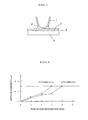
- a bare fin 1 formed of an Al-Mn alloy is combined with a tube material 2 formed by bending a sheet material in which an Al-Si alloy filler metal containing Zn is clad on an aluminum alloy core material 4.
- a Zn diffusion layer 3 is formed on the surface of the tube material 2, and the filler metal 3 is melted to form a fillet F, whereby the bare fin 1 and the tube material 2 are brazed.
- the potential of the surface of the tube material 2 must be lower than the potential of the core material 4 of the tube material 2 from the viewpoint of corrosion protection of the tube material 2.
- Zn is added to the Al-Si alloy filler metal 3, and the Zn diffusion layer 3 is formed on the surface of the tube material 2 during heating for brazing.
- consumption of the Zn diffusion layer in normal corrosive solution is increased due to Si diffused together with Zn, penetration corrosion tends to occur directly under or near the brazed section in early stages.
- this method does not necessarily provide sufficient corrosion resistance depending on use environment of the automotive aluminum heat exchanger.
- the present inventors have conducted various tests and studies on the measure to improve corrosion resistance of the tube material in order to provide excellent corrosion resistance to an aluminum heat exchanger assembled by brazing an aluminum tube material formed by bending a sheet material which enables a reduction of the thickness as the tube material to an aluminum fin material in the actual use environment. As a result, the present inventors have found the following facts.
- corrosion protection properties are evaluated by using the same concentration of a corrosive solution, such as in a continuous spraying method such as a CASS test.
- concentration of corrosive water is not constant, since wet and dry conditions repeatedly occur.
- chlorine ion or the like is expected to concentrate.
- aluminum has different potentials depending on the chlorine ion concentration in corrosive water, sufficient corrosion resistance cannot be achieved unless the chlorine ion concentration corresponding to the actual use environment is taken into consideration. In order to evaluate practical corrosion resistance, it is necessary to evaluate corrosion resistance taking this point into consideration.
- An object of the present invention is to provide an aluminum heat exchanger excellent in corrosion resistance which is assembled by brazing an aluminum fin material to the outer surface of an aluminum tube material formed by bending a sheet material, includes a tube material having practically improved corrosion resistance, and is suitably used as an automotive heat exchanger.
- one aspect of the present invention provides an aluminum heat exchanger excellent in corrosion resistance which is assembled by brazing an aluminum fin material to an outer surface of a tube material made of aluminum formed by bending a sheet material, wherein the tube material is formed of a two-layer clad sheet which includes a core material and an Al-Zn alloy layer clad on the core material, the Al-Zn alloy layer is clad on the outer surface of the tube material and brazed to the aluminum fin material, a potential (natural potential, hereinafter the same) of the Al-Zn alloy layer in normal corrosive solution is 100 mV or more lower than a potential of the core material in the normal corrosive solution, and a potential of the Al-Zn alloy layer in the normal corrosive solution is lower than a potential of the core material in high-concentration corrosive water.
- the normal corrosive solution refers to an aqueous solution containing 10 g/l of NaCl and 0.3 g/l of Na 2 SO 4
- the high concentration corrosive water refers to an aqueous solution in which the NaCl concentration is increased by 30 times by concentrating the above aqueous solution.
- a potential of a brazed section between the Al-Zn alloy layer of the tube material and the aluminum fin material in the corrosive water may be 100 mV or more lower than the potential of the core material in the corrosive water, and the potential of the brazed section between the Al-Zn alloy layer of the tube material and the aluminum fin material in the corrosive water may be lower than the potential of the core material of the tube material in the high-concentration corrosive water.
- the Al-Zn alloy layer of the tube material may comprise 2.0-7.5% of Zn.
- the core material of the tube material may be an Al-Mn alloy.
- the Al-Mn alloy may comprise more than 1.5% of Mn.
- the tube material may have a thickness of 100-300 ⁇ m, and the thickness of a sacrificial anode material may be 10-40% of the thickness of the tube material.
- the aluminum fin material on which an Al-Si alloy filler metal is clad may be brazed to an inner surface of the tube material.
- the tube material may be formed of a three-layer clad sheet in which an Al-Si alloy filler metal is further clad on the core material of the two-layer clad sheet, the Al-Si alloy filler metal may be clad on the inner surface of the tube material, and the aluminum fin material may be brazed to the inner surface of the tube material.
- the tube material may have a thickness of 100-300 ⁇ m, the thickness of a sacrificial anode material may be 10-40% of the thickness of the tube material, and the thickness of the Al-Si alloy filler metal may be 5-30% of the thickness of the tube material.
- the aluminum fin material on which an Al-Si alloy filler metal is clad may be brazed to the outer surface of the tube material.
- the aluminum fin material in which an Al-Si alloy may be brazed to the outer surface of the tube material using a powdered filler metal.
- At least one of the Al-Si alloy filler metal and the aluminum fin material may comprise 0.3-3.0% of Zn.
- the aluminum fin material may comprise 0.3-3.0% of Zn.
- an aluminum heat exchanger excellent in corrosion resistance which is assembled by brazing an aluminum fin material to the outer surface of an aluminum tube material formed by bending a sheet material, includes a tube material having improved corrosion resistance, and has excellent corrosion resistance can be provided.
- the aluminum heat exchanger can be suitably used as an automotive heat exchanger such as a condenser or evaporator.
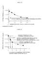
- each of a sheet material in which an Al-2. 2%Zn alloy was clad on the outer surface of a core material made of an Al-1.2%Mn alloy (thickness: 0.15 mm) (specimen No.
- the potential applied was -570 mV vs Ag/AgCl.
- a solution to which 10 g/l of NaCl and 0.3 g/l of Na 2 SO 4 were added was used as a corrosive solution.
- FIG. 2 the test results show that the specimen No. 1 on which the Al-Zn alloy was clad has corrosion resistance better than the specimen No. 2 on which the Al-Si-Zn alloy was clad. It is estimated that early corrosion occurred in the Zn diffusion layer of the specimen No. 2 on which the Al-Si-Zn alloy was clad due to the effects of Si. It was confirmed that the tube material on which the Al-Zn alloy layer which does not contain Si is clad is better from the viewpoint of corrosion resistance.
- A3003 alloy Al-Mn alloy
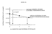
- a change in potential in concentrated water obtained by concentrating corrosive water are described below.
- As the normal corrosive solution a solution to which 10 g/l of NaCl and 0.3 g/l of Na 2 SO 4 were added was used as a reference solution.
- the potential was measured in a solution in which the chlorine ion concentration was increased by concentrating the reference solution. The results are shown in FIG. 3. In this case, the solubility of NaCl is about 26%. Therefore, the maximum chlorine concentration is 30 times.
- the A3003 alloy core material has a potential of -620 mV in the reference solution. Since the sacrificial anode material exhibits a sacrificial anode effect in the normal corrosive solution if the potential of the sacrificial anode material clad on the core material has a potential 100 mV or more lower than the potential of the core material, the potential of the sacrificial anode material in the normal corrosive solution must be -720mV or less.
- the potential of the A3003 alloy is about -780 mV, which is 160 mV lower than the potential in the normal corrosive solution. Therefore, in order to obtain sufficient corrosion resistance in the corrosive environment assuming a high concentration of corrosive water, the potential of the sacrificial anode material in the normal corrosive solution must be lower than the potential of the A3003 alloy core material in the high-concentration corrosive water, specifically, the potential of the sacrificial anode material in the normal corrosive solution must be lower than -780mV.
- the tube material can be provided with excellent corrosion resistance by a configuration in which the tube material is formed of a core material and an Al-Zn alloy layer clad on the outer surface of the core material, the potential of the Al-Zn alloy layer in the normal corrosive solution is 100 mV or more lower than the potential of the core material in the normal corrosive solution, and the potential of the Al-Zn alloy layer in the normal corrosive solution is lower than the potential of the core material in the high-concentration corrosive water.
- FIG. 4 shows measurement results for the natural potential in the normal corrosive solution after heating a tube material in which an Al-Zn alloy having a different Zn content was clad on an A3003 alloy core material to a brazing temperature (600°C) .
- the Zn concentration in the sacrificial anode material must be 1.0% or more in order to allow the Al-Zn alloy sacrificial anode material to have a potential 100 mV or more lower than the potential of the A3003 alloy core material, specifically, to have a potential of -720 mV or less in the normal corrosive solution.
- the potential of the A3003 alloy is - 780 mV in the high-concentration corrosive water in which the NaCl concentration was increased by 30 times by concentrating the normal corrosive solution. Therefore, the potential of the sacrificial anode material in the normal corrosive solution is lower than -780 mV in order to obtain sufficient corrosion resistance in the corrosive environment assuming high-concentration corrosive water. Therefore, the Zn concentration in the sacrificial anode material must be 2.0% or more. If the Zn concentration exceeds 7.5%, preferential corrosion may occur in the brazed section. Therefore, the suitable range of the Zn concentration in the Al-Zn alloy sacrificial anode material is preferably 2.0-7.5%.
- an aluminum alloy which includes 1. 0-2. 0% of Mn or 1.0-2.0% of Mn and 0.05-0.6% of Cu, and further includes 1.0% or less of Si, 0.7% or less of Fe, and 0.1% or less of Zn as impurities, or an aluminum alloy in which 0.2% or less of Ti or 0. 5% or less of Mg is added to the above aluminum alloy may be used as the core material of the tube material.
- an aluminum alloy which includes 2.0-7.5% of Zn, and may further include 2.0% or less of Si, 0.4% or less of Fe, 0.2% or less of Cu, 2.0% or less of Mn, 0.3% or less of Mg, and 0.2% or less of Ti may be used.
- Al-Mn alloy which includes more than 1.5%, but 2.0% or less of Mn, and preferably 1.6-2.0% of Mn as the core material, and an Al-Zn alloy which includes 2.0-7.5% of Zn, and preferably 2.5-7.5% of Zn as the sacrificial anode material.
- This combination allows the potential of the Al-Zn alloy layer in the normal corrosive solution to be 150 mV or more lower than the potential of the core material in the normal corrosive solution, and the potential of the Al-Zn alloy layer in the normal corrosive solution to be 50 mV lower than the potential of the core material in the high-concentration corrosive water, whereby an aluminum heat exchanger having excellent corrosion resistance in which corrosion resistance of the tube material is significantly improved can be obtained.
- Mn added to the core material increases the potential of the core material.
- the potential of the core material is increased as the Mn content is increased. Since Mn is rarely diffused even if heating for brazing is performed, Mn moves from the interface between the core material and the sacrificial anode material only to a small extent.
- Zn added to the sacrificial anode material is diffused into the core material by heating for brazing to form a diffusion layer from the surface in the direction of the depth.
- the concentration gradient of Zn specifically, potential gradient occurs from the surface in the direction of the depth, whereby the surface of the tube material is protected against corrosion.
- Mn is distributed only on the side of the core material from the interface before heating for brazing (hereinafter called “interface before brazing”), the potential gradient is rapidly increased at the interface before brazing, and corrosion which has proceeded from the surface stops at the interface before brazing. In order to obtain this effect, it is preferable to add Mn to the core material in an amount of more than 1.5%, and still more preferably 1.6% or more.
- the present invention is effective when applied to a heat exchanger in which the tube material is formed by bending a two-layer clad sheet in which an Al-Zn alloy layer (sacrificial anode material) is clad on an aluminum alloy core material so that the Al-Zn alloy layer (sacrificial anode material) is on the outer surface, and an aluminum fin material is assembled and brazed to the Al-Zn alloy layer (sacrificial anode material) on the outer surface of the tube material, or to a heat exchanger in which the tube material is formed by bending a three-layer clad sheet in which an Al-Zn alloy layer (sacrificial anode material) is clad on one side of an aluminum alloy core material and an Al-Si alloy filler metal is clad on the other side so that the Al-Zn alloy layer (sacrificial anode material) is on the outer surface and the Al-Si alloy filler metal is on the inner surface, an aluminum fin material is assembled and brazed to the Al-
- corrosion resistance is effectively obtained by adjusting the thickness of the tube material to 100-300 ⁇ m, and the thickness of the sacrificial anode material to 10-40% of the thickness of the tube material.
- corrosion resistance is effectively obtained by adjusting the thickness of the tube material to 100-300 ⁇ m, the thickness of the sacrificial anode material to 10-40% of the thickness of the tube material, and the thickness of the filler metal to 5-30% of the thickness of the tube material.
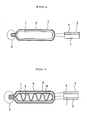
- a tube material 5 which is formed by bending a two-layer clad sheet which includes a core material 7 and an Al-Zn alloy layer 8 clad on the core material 7, and mechanically joining, such as staking, both ends in a section A shown in FIG. 6 can be given.
- a tube material 6 which is formed by bending a three-layer clad sheet in which an Al-Si alloy filler metal 9 is further clad on the core material 7 of the two-layer clad sheet, and an aluminum fin 10 is assembled, and mechanically joining, such as staking, both ends in a section B shown in FIG. 7 can be given.
- a product formed by corrugating a brazing sheet in which an A4045 alloy filler metal was clad on an Al-Mn alloy core material was used as the fin material, and a sheet material in which an Al-2.0%Zn alloy was clad on an A3003 alloy core material was used as the tube material.
- the fin material and the tube material were assembled and brazed by inert gas brazing using a fluoride-type flux. Since it is difficult to measure the potential of the brazed section, a method in which the brazed section is electrolyzed to corrode the eutectic phase, and the potential of the alpha phase removed is measured was used. The potential of the alpha phase measured was about -700 mV. As the corrosive water, a solution to which 10 g/l of NaCl and 0.3 g/l of Na 2 SO 4 were added was used.
- FIG. 5 shows the relationship between the amount of Zn added to the filler metal of the fin material and the natural potential of the alpha phase in the normal corrosive solution.
- a brazing sheet in which a filler metal in which 1.0% of Zn was added to an A4045 alloy was clad on an Al-Mn alloy core material was used as the fin material, and the potential of the alpha phase was measured in the same manner as described above. As a result, the potential of the alpha phase was -750 mV. Therefore, it was confirmed that the addition of Zn to the filler metal decreases the potential of the alpha phase of the filler metal and improves the sacrificial corrosion effect of the fin material, as shown in FIG. 5.
- the potential of the alpha phase of the filler metal of the fin material must be 100 mV or more lower than the potential of the A3003 alloy core material of the tube material in the normal corrosive solution. Therefore, 0.3% or more of Zn must be added to the filler metal of the fin material, as shown in FIG. 5. As shown in FIG. 5, Zn is preferably added to the filler metal of the fin material in an amount of 1.8% or more taking concentration of corrosive water into consideration.
- the potential of the alpha phase of the filler metal of the fin material is significantly higher than the potential of the sacrificial corrosion material of the tube material, consumption of the sacrificial corrosion material of the tube material is increased to a large extent, whereby the corrosion life of the tube material is decreased.
- the suitable range of the Zn concentration in the filler metal of the fin material differs depending on the Zn content in the sacrificial corrosion material of the tube material, the same measurement as described above was performed while changing the Zn content in the sacrificial corrosion material of the tube material to 1.0%, 2.0%, 5.0%, and 7.5% assuming various types of corrosion environment. As a result, it was confirmed that excellent corrosion resistance is obtained in the case of adding 0.3-3.0%, and preferably 1.0-3.0% of Zn to the filler metal of the fin material.
- the above-described example illustrates the case where the brazing sheet in which the Al-Si A4045 alloy filler metal is clad on the Al-Mn alloy core material is applied as the fin material.
- an Al-Mn alloy fin material (bare fin) may be used as the fin material, and the fin material and the tube material may be brazed by applying powdered filler metal to the brazing section.
- An aluminum alloy containing 0.5% of Si, 0.6% of Fe, 1.2% of Mn, 0.1% of Cu, 0.05% of Zn, and 0.02% of Ti, the balance being Al and unavoidable impurities was used as an aluminum alloy for a core material of a tube material, and an aluminum alloy containing 2.5% of Zn, 0.4% of Si, 0.5% of Fe, 0.1% of Cu, the balance being Al and unavoidable impurities was used as an aluminum alloy for a sacrificial anode material of the tube material.
- the aluminum alloys were cast by semicontinuous casting. The resulting ingots were homogenized and hot-rolled. The hot-rolled products were stacked and hot-rolled to obtain a clad material.
- the clad material was cold-rolled, process-annealed, and subjected to final cold rolling to obtain a tube material (sheet material) with a thickness of 0.15 mm (specimen No. 1).
- a hot-rolled product of the above aluminum alloy for a core material was used as an aluminum alloy for a core material of the tube material.
- An aluminum alloy containing 5.0% of Zn, 7.5% of Si, 0.4% of Fe, 0.2% of Cu, the balance being Al and unavoidable impurities as an aluminum alloy for a sacrificial anode material of the tube material was cast by semicontinuous casting.
- the resulting ingot was homogenized and hot-rolled.
- the hot-rolled product was stacked on the hot-rolled product of the aluminum alloy for a core material and hot-rolled to obtain a clad material.
- the clad material was cold-rolled, process-annealed, and subjected to final cold rolling to obtain a tube material (sheet material) with a thickness of 0.15 mm (specimen No. 2).
- An aluminum alloy containing 0.3% of Si, 0.3% of Fe, 1.0% of Mn, 0.1% of Cu, 1.0% of Zn, and 0.01% of Ti, the balance being Al and unavoidable impurities was used as an aluminum alloy for a core material of a fin material, and an A4045 alloy (10% of Zn, 0.4% of Fe, 0.1% of Cu, 0.02% of Mn, and 1.0% of Zn, the balance being Al and unavoidable impurities) was used as an aluminum alloy for a filler metal of the fin material.
- the aluminum alloys were cast by semicontinuous casting.
- the aluminum alloy ingot for the core material was homogenized and hot-rolled.
- the aluminum alloy for a filler metal was hot-rolled.
- the resulting products were stacked and hot-rolled to obtain a clad material.
- the clad material was cold-rolled, process-annealed, and subjected to final cold rolling to obtain a clad fin material (H14 temper) with a thickness of 0.10 mm.
- the resulting clad fin material was corrugated.
- a mini core (miniature model of heat exchanger core) was formed by assembling the corrugated fin with each of the tube materials of the specimens No. 1 and No. 2, and brazing the fin and the tube material. Brazing was performed by applying a fluoride-type flux (concentration: 3%) and heating the mini core at 600°C for five minutes in a nitrogen gas atmosphere in the same manner as the brazing conditions using a fluoride-type flux.
- the mini core after brazing was subjected to the controlled potential electrolysis test (applied potential: -570 mV vs Ag/AgCl, corrosive solution: aqueous solution to which 10 g/l of NaCl and 0.3 g/l of Na 2 SO 4 0 were added).
- the controlled potential electrolysis test applied potential: -570 mV vs Ag/AgCl, corrosive solution: aqueous solution to which 10 g/l of NaCl and 0.3 g/l of Na 2 SO 4 0 were added.
- penetration corrosion did not occur during four days of test in the mini core in which the specimen No. 1 was used as the tube material.
- penetration corrosion occurred after three days of test in the mini core in which the specimen No. 2 was used as the tube material.
- An aluminum alloy containing 0.75% of Si, 0.18% of Fe, 1.65% of Mn, 0.3% of Cu, 0.75% of Zn, and 0.14% of Ti, the balance being Al and unavoidable impurities was as an aluminum alloy for a core material of a tube material, and an aluminum alloy containing 2.9% of Zn, 0.4% of Si, 0.4% of Fe, 0. 1% of Cu, the balance being Al and unavoidable impurities was used as an aluminum alloy for a sacrificial anode materials of the tube material.
- the aluminum alloys were cast by semicontinuous casting. The resulting ingots were homogenized and hot-rolled. The hot-rolled products were stacked and hot-rolled to obtain a clad material.
- the clad material was cold-rolled, process-annealed, and subjected to final cold rolling to obtain a tube material (sheet material) with a thickness of 0.2 mm (specimen No. 3).
- the thickness of the sacrificial anode material layer was 20% of the entire thickness.
- An aluminum alloy containing 0.4% of Si, 0.3% of Fe, 1.2% of Mn, 0.1% of Cu, 1.15% of Zn, 0.08% of Cr, and 0.01% of Ti, the balance being Al and unavoidable impurities was used as an aluminum alloy for a core material of a fin material, and an A4045 alloy (10% of Zn, 0.4% of Fe, 0.1% of Cu, 0.02% of Mn, and 1.0% of Zn, the balance being Al and unavoidable impurities) was used as an aluminum alloy for a filler metal of the fin material.
- the aluminum alloys were cast by semicontinuous casting.
- the aluminum alloy ingot for the core material was homogenized and hot-rolled.
- the aluminum alloy for a filler metal was hot-rolled.
- the resulting products were stacked and hot-rolled to obtain a clad material.
- the clad material was cold-rolled, process-annealed, and subjected to final cold rolling to obtain a clad fin material (H14 temper) with a thickness of 0.05 mm.
- the resulting clad fin material was corrugated.
- a mini core (miniature model of heat exchanger core) was formed by assembling the corrugated fin with the tube material of the specimen No. 3, and brazing the corrugated fin and the tube material. Brazing was performed by applying a fluoride-type flux (concentration: 3%) and heating the mini core at 600°C for five minutes in a nitrogen gas atmosphere in the same manner as the brazing conditions using a fluoride-type flux.
- the mini core after brazing was subjected to the controlled potential electrolysis test (applied potential: -570 mV vs Ag/AgCl, corrosive solution: aqueous solution to which 10 g/l of NaCl and 3 g/l of Na 2 SO 4 0 were added).
- the controlled potential electrolysis test applied potential: -570 mV vs Ag/AgCl, corrosive solution: aqueous solution to which 10 g/l of NaCl and 3 g/l of Na 2 SO 4 0 were added.
Landscapes
- Engineering & Computer Science (AREA)
- Physics & Mathematics (AREA)
- Thermal Sciences (AREA)
- Mechanical Engineering (AREA)
- General Engineering & Computer Science (AREA)
- Geometry (AREA)
- Prevention Of Electric Corrosion (AREA)
- Laminated Bodies (AREA)
Applications Claiming Priority (4)
| Application Number | Priority Date | Filing Date | Title |
|---|---|---|---|
| JP2003161863 | 2003-06-06 | ||
| JP2003161863 | 2003-06-06 | ||
| JP2004155813A JP2005016937A (ja) | 2003-06-06 | 2004-05-26 | 耐食性に優れたアルミニウム製熱交換器 |
| JP2004155813 | 2004-05-26 |
Publications (3)
| Publication Number | Publication Date |
|---|---|
| EP1484571A2 true EP1484571A2 (de) | 2004-12-08 |
| EP1484571A3 EP1484571A3 (de) | 2013-04-24 |
| EP1484571B1 EP1484571B1 (de) | 2018-07-25 |
Family
ID=33161590
Family Applications (1)
| Application Number | Title | Priority Date | Filing Date |
|---|---|---|---|
| EP04013142.7A Expired - Lifetime EP1484571B1 (de) | 2003-06-06 | 2004-06-03 | Korrosionsbeständiger Aluminium-Wärmetauscher |
Country Status (4)
| Country | Link |
|---|---|
| US (1) | US7250223B2 (de) |
| EP (1) | EP1484571B1 (de) |
| JP (1) | JP2005016937A (de) |
| CN (1) | CN100478640C (de) |
Cited By (3)
| Publication number | Priority date | Publication date | Assignee | Title |
|---|---|---|---|---|
| EP2243589A1 (de) * | 2009-04-21 | 2010-10-27 | Sumitomo Light Metal Industries, Ltd. | Plattiertes Aluminiumlegierungsblech für Wärmetauscher und Herstellungsverfahren dafür |
| CZ304647B6 (cs) * | 2005-04-12 | 2014-08-20 | Kabushiki Kaisha Kobe Seiko Sho | Pájecí plech ze slitin hliníku a trubka výměníku tepla ze slitin hliníku |
| EP3112792A1 (de) * | 2015-07-03 | 2017-01-04 | Samsung Electronics Co., Ltd. | Wärmetauscher und klimaanlage damit |
Families Citing this family (41)
| Publication number | Priority date | Publication date | Assignee | Title |
|---|---|---|---|---|
| US20050034794A1 (en) * | 2003-04-10 | 2005-02-17 | Rinze Benedictus | High strength Al-Zn alloy and method for producing such an alloy product |
| US7666267B2 (en) | 2003-04-10 | 2010-02-23 | Aleris Aluminum Koblenz Gmbh | Al-Zn-Mg-Cu alloy with improved damage tolerance-strength combination properties |
| ES2393366B2 (es) | 2003-04-10 | 2013-07-01 | Aleris Aluminum Koblenz Gmbh | UNA ALEACIÓN DE Al-Zn-Mg-Cu. |
| US20060032560A1 (en) * | 2003-10-29 | 2006-02-16 | Corus Aluminium Walzprodukte Gmbh | Method for producing a high damage tolerant aluminium alloy |
| US7883591B2 (en) * | 2004-10-05 | 2011-02-08 | Aleris Aluminum Koblenz Gmbh | High-strength, high toughness Al-Zn alloy product and method for producing such product |
| JP2008523296A (ja) * | 2004-12-13 | 2008-07-03 | ベール ゲーエムベーハー ウント コー カーゲー | 酸を含むガスのための熱を交換する装置 |
| WO2007026481A1 (ja) * | 2005-08-31 | 2007-03-08 | Showa Denko K.K. | クラッド材およびその製造方法 |
| FR2907796B1 (fr) * | 2006-07-07 | 2011-06-10 | Aleris Aluminum Koblenz Gmbh | Produits en alliage d'aluminium de la serie aa7000 et leur procede de fabrication |
| WO2008003504A2 (en) * | 2006-07-07 | 2008-01-10 | Aleris Aluminum Koblenz Gmbh | Aa7000-series aluminium alloy products and a method of manufacturing thereof |
| CN101925791A (zh) * | 2007-11-30 | 2010-12-22 | 霍尔泰克国际股份有限公司 | 用于风冷式热交换器的翅片管装置及其制造方法 |
| WO2009101896A1 (ja) * | 2008-02-12 | 2009-08-20 | Kabushiki Kaisha Kobe Seiko Sho | アルミニウム合金積層板 |
| DE102008031614A1 (de) * | 2008-07-07 | 2010-01-14 | Behr Gmbh & Co. Kg | Wärmeübertrager, insbesondere Wärmeübertrager eines Kraftfahrzeuges, und Verfahren zum Herstellen eines Kühlrohres eines Wärmeübertragers |
| EP2159528B1 (de) * | 2008-09-02 | 2015-11-04 | Calsonic Kansei Corporation | Wärmetauscher aus Aluminiumlegierung |
| DE102008059450A1 (de) * | 2008-11-28 | 2010-06-02 | Behr Gmbh & Co. Kg | Aluminiumband, Lötbauteil, Herstellungsverfahren und Wärmetauscher und Verwendung |
| JP5577616B2 (ja) * | 2009-04-06 | 2014-08-27 | 株式会社デンソー | 熱交換器用チューブ及び熱交換器 |
| JP5302751B2 (ja) | 2009-04-21 | 2013-10-02 | 株式会社デンソー | 熱交換器用アルミニウム合金クラッド材 |
| JP5610714B2 (ja) * | 2009-06-24 | 2014-10-22 | 株式会社Uacj | アルミニウム合金製熱交換器 |
| DE102009055608A1 (de) * | 2009-11-25 | 2011-05-26 | Behr Gmbh & Co. Kg | Gelöteter Aluminium-Wärmeübertrager |
| CN104722872B (zh) | 2010-03-02 | 2016-08-03 | 三菱铝株式会社 | 铝合金制热交换器 |
| BR112013027220A2 (pt) * | 2011-04-25 | 2016-12-27 | Delphi Tech Inc | método para fabricar um trocador de calor de alumínio |
| JP6216964B2 (ja) * | 2011-08-09 | 2017-10-25 | 三菱アルミニウム株式会社 | 冷却器用クラッド材および発熱素子用冷却器 |
| WO2013084433A1 (ja) * | 2011-12-09 | 2013-06-13 | パナソニック株式会社 | 空気調和機の熱交換器 |
| DK2836785T3 (da) * | 2012-04-12 | 2023-01-09 | Carrier Corp | Lamelvarmeveksler af en aluminiumslegering |
| WO2014076949A1 (ja) * | 2012-11-14 | 2014-05-22 | パナソニック株式会社 | Al合金管の接合体、ならびに、これを用いた熱交換器 |
| JP2015140457A (ja) * | 2014-01-29 | 2015-08-03 | 株式会社ケーヒン・サーマル・テクノロジー | 熱交換器 |
| EP3176273B1 (de) | 2014-07-30 | 2018-12-19 | UACJ Corporation | Lötblech aus einer aluminiumlegierung |
| JP6498911B2 (ja) * | 2014-11-10 | 2019-04-10 | 三菱アルミニウム株式会社 | 高強度・高耐食性・素材高伸びを有するアルミニウム合金ブレージングシート |
| JP6483412B2 (ja) | 2014-11-21 | 2019-03-13 | 株式会社デンソー | 熱交換器用アルミニウム合金クラッド材 |
| JP6474589B2 (ja) | 2014-11-21 | 2019-02-27 | 株式会社Uacj | 熱交換器用アルミニウム合金クラッド材 |
| CN107073618B (zh) * | 2014-12-11 | 2019-05-28 | 株式会社Uacj | 钎焊方法 |
| EP3340785B1 (de) | 2015-08-27 | 2020-11-18 | Renew Health Limited | Wasserbehandlungssystem |
| CN106855162A (zh) * | 2015-12-09 | 2017-06-16 | 王翔 | 一种防腐蚀空调管 |
| JP6186455B2 (ja) | 2016-01-14 | 2017-08-23 | 株式会社Uacj | 熱交換器及びその製造方法 |
| JP6312968B1 (ja) | 2016-11-29 | 2018-04-18 | 株式会社Uacj | ブレージングシート及びその製造方法 |
| MX2019010905A (es) | 2017-03-19 | 2020-02-13 | Renew Health Ltd | Sistema de tratamiento de agua y metodo de uso del mismo. |
| JP2019070499A (ja) * | 2017-10-11 | 2019-05-09 | 株式会社ケーヒン・サーマル・テクノロジー | 熱交換器の製造方法 |
| JP6522178B1 (ja) * | 2018-01-31 | 2019-05-29 | ダイキン工業株式会社 | 冷媒分流器及び空気調和機 |
| JP7058175B2 (ja) * | 2018-05-21 | 2022-04-21 | 株式会社Uacj | アルミニウム合金製熱交換器 |
| JP7058176B2 (ja) * | 2018-05-21 | 2022-04-21 | 株式会社Uacj | アルミニウム合金製熱交換器 |
| US11685973B2 (en) | 2018-06-21 | 2023-06-27 | Arconic Technologies Llc | Corrosion resistant high strength brazing sheet |
| CN117002104A (zh) * | 2022-04-27 | 2023-11-07 | 杭州三花微通道换热器有限公司 | 一种用于换热器的换热管及换热器 |
Citations (1)
| Publication number | Priority date | Publication date | Assignee | Title |
|---|---|---|---|---|
| JP2001071172A (ja) | 1999-09-06 | 2001-03-21 | Shinko Alcoa Yuso Kizai Kk | 耐食性が優れたブレージングシート |
Family Cites Families (28)
| Publication number | Priority date | Publication date | Assignee | Title |
|---|---|---|---|---|
| US3859058A (en) * | 1973-10-04 | 1975-01-07 | Alusuisse | Corrosion resistant aluminum composite material |
| JPS59100250A (ja) | 1982-12-01 | 1984-06-09 | Nippon Radiator Co Ltd | アルミニウム製熱交換器用板材 |
| JP2753634B2 (ja) * | 1989-09-06 | 1998-05-20 | 株式会社神戸製鋼所 | チューブ材用アルミニウム合金複合材シート |
| US5148862A (en) * | 1990-11-29 | 1992-09-22 | Sumitomo Light Metal Industries, Ltd. | Heat exchanger fin materials and heat exchangers prepared therefrom |
| US5217547A (en) * | 1991-05-17 | 1993-06-08 | Furukawa Aluminum Co., Ltd. | Aluminum alloy fin material for heat exchanger |
| CA2112441C (en) * | 1992-12-29 | 2005-08-09 | Tomiyoshi Kanai | Corrosion-resistant and brazeable aluminum material and a method of producing same |
| JPH06272069A (ja) * | 1993-03-22 | 1994-09-27 | Nippon Light Metal Co Ltd | 犠牲陽極を使用したAl合金製ラジエータの防食 |
| JPH08260085A (ja) * | 1995-03-17 | 1996-10-08 | Furukawa Electric Co Ltd:The | 耐食性に優れた真空ブレージング用アルミニウム合金複合材 |
| JPH09302432A (ja) * | 1996-05-15 | 1997-11-25 | Furukawa Electric Co Ltd:The | 熱交換器のフイン用ブレージングシート |
| US6129143A (en) * | 1996-08-08 | 2000-10-10 | Denso Corporation | Brazing sheet having an excellent corrosion resistance for use in a heat exchanger, and a heat exchanger using the same |
| JP3819080B2 (ja) * | 1996-09-05 | 2006-09-06 | 三菱アルミニウム株式会社 | 耐食性に優れた熱交換器 |
| JPH1129835A (ja) | 1997-07-14 | 1999-02-02 | Kobe Steel Ltd | 耐食性に優れるろう付けタイプの熱交換器用Zn被覆アルミニウム押出管 |
| JPH1180870A (ja) * | 1997-09-08 | 1999-03-26 | Sumitomo Light Metal Ind Ltd | 強度および耐食性に優れた熱交換器用アルミニウム合金クラッド材 |
| JPH11172357A (ja) * | 1997-12-15 | 1999-06-29 | Denso Corp | 真空ろう付け用耐食アルミニウム合金クラッド材 |
| JP3908847B2 (ja) * | 1998-02-10 | 2007-04-25 | 古河スカイ株式会社 | 熱交換器用アルミニウム合金犠牲陽極材および熱交換器用高耐食性アルミニウム合金複合材 |
| JP3772017B2 (ja) * | 1998-04-07 | 2006-05-10 | 住友軽金属工業株式会社 | 熱交換器用高強度高耐食アルミニウム合金クラッド材 |
| JP3197251B2 (ja) * | 1998-09-22 | 2001-08-13 | カルソニックカンセイ株式会社 | 熱交換器用犠牲防食アルミニウム合金、および熱交換器用高耐食性アルミニウム合金複合材 |
| JP2000135588A (ja) * | 1998-10-29 | 2000-05-16 | Sumitomo Light Metal Ind Ltd | 耐食性に優れた熱交換器用高強度アルミニウム合金クラッド材 |
| JP2000204427A (ja) * | 1999-01-11 | 2000-07-25 | Sumitomo Light Metal Ind Ltd | ろう付け性と耐食性に優れた熱交換器用アルミニウム合金クラッド材 |
| US6316126B1 (en) * | 1999-02-23 | 2001-11-13 | Denso Corporation | Aluminum alloy clad material for heat exchangers exhibiting excellent erosion-corrosion resistance |
| JP2000317673A (ja) * | 1999-05-13 | 2000-11-21 | Furukawa Electric Co Ltd:The | ろう付け性に優れたブレージングシート |
| JP2001050690A (ja) * | 1999-05-28 | 2001-02-23 | Denso Corp | アルミニウム合金製熱交換器 |
| EP1090745B1 (de) * | 1999-10-04 | 2002-06-19 | Denso Corporation | Mit einer Aluminium-Legierung plattiertes Material für einen Wärmetauscher mit hoher Festigkeit und guter Korrosionsbeständigkeit |
| JP2002062088A (ja) * | 2000-08-10 | 2002-02-28 | Denso Corp | アルミニウム熱交換器 |
| JP4451974B2 (ja) * | 2000-08-10 | 2010-04-14 | 古河スカイ株式会社 | 熱交換器用アルミニウム合金製ブレージングシート |
| JP2002254167A (ja) * | 2001-03-02 | 2002-09-10 | Asahi Tec Corp | ろう付け方法及びマグネシウム含有アルミニューム合金製品 |
| CN2543018Y (zh) * | 2002-04-18 | 2003-04-02 | 北京森德散热器有限公司 | 带有防腐保护层的散热器 |
| US20060086486A1 (en) * | 2002-10-30 | 2006-04-27 | Showa Denko K.K. | Heat exchanger, heat exchanger tube member, heat exchanger fin member and process for fabricating the heat exchanger |
-
2004
- 2004-05-26 JP JP2004155813A patent/JP2005016937A/ja active Pending
- 2004-06-03 US US10/860,560 patent/US7250223B2/en not_active Expired - Lifetime
- 2004-06-03 EP EP04013142.7A patent/EP1484571B1/de not_active Expired - Lifetime
- 2004-06-04 CN CNB2004100462859A patent/CN100478640C/zh not_active Expired - Lifetime
Patent Citations (1)
| Publication number | Priority date | Publication date | Assignee | Title |
|---|---|---|---|---|
| JP2001071172A (ja) | 1999-09-06 | 2001-03-21 | Shinko Alcoa Yuso Kizai Kk | 耐食性が優れたブレージングシート |
Cited By (3)
| Publication number | Priority date | Publication date | Assignee | Title |
|---|---|---|---|---|
| CZ304647B6 (cs) * | 2005-04-12 | 2014-08-20 | Kabushiki Kaisha Kobe Seiko Sho | Pájecí plech ze slitin hliníku a trubka výměníku tepla ze slitin hliníku |
| EP2243589A1 (de) * | 2009-04-21 | 2010-10-27 | Sumitomo Light Metal Industries, Ltd. | Plattiertes Aluminiumlegierungsblech für Wärmetauscher und Herstellungsverfahren dafür |
| EP3112792A1 (de) * | 2015-07-03 | 2017-01-04 | Samsung Electronics Co., Ltd. | Wärmetauscher und klimaanlage damit |
Also Published As
| Publication number | Publication date |
|---|---|
| EP1484571B1 (de) | 2018-07-25 |
| EP1484571A3 (de) | 2013-04-24 |
| JP2005016937A (ja) | 2005-01-20 |
| CN1573275A (zh) | 2005-02-02 |
| US7250223B2 (en) | 2007-07-31 |
| US20050011636A1 (en) | 2005-01-20 |
| CN100478640C (zh) | 2009-04-15 |
Similar Documents
| Publication | Publication Date | Title |
|---|---|---|
| EP1484571B1 (de) | Korrosionsbeständiger Aluminium-Wärmetauscher | |
| EP1090745B1 (de) | Mit einer Aluminium-Legierung plattiertes Material für einen Wärmetauscher mit hoher Festigkeit und guter Korrosionsbeständigkeit | |
| JP6243837B2 (ja) | 熱交換器用アルミニウム合金製ブレージングシート、ならびに熱交換器用アルミニウム合金製ろう付け体およびその製造方法 | |
| US4991647A (en) | Heat exchanger | |
| US7135239B2 (en) | Composite material made of high-strength aluminum alloy | |
| JP5873343B2 (ja) | 高耐食性アルミニウム合金ブレージングシート、ならびに、これを用いた自動車用熱交換器の流路形成部品 | |
| EP3222738B1 (de) | Aluminiumlegierungsplattierungsmaterial für einen wärmetauscher | |
| CN112041472B (zh) | 铝合金制换热器 | |
| JP4190295B2 (ja) | 耐食性に優れたアルミニウム合金クラッドチューブ材および該クラッドチューブ材を組付けた熱交換器 | |
| JPH11172357A (ja) | 真空ろう付け用耐食アルミニウム合金クラッド材 | |
| JP4263160B2 (ja) | アルミニウム合金クラッド材並びにそれを用いた熱交換器用チューブ及び熱交換器 | |
| JPH09176767A (ja) | 真空ろう付用Alブレージングシート | |
| JP2691069B2 (ja) | 耐食性及び伝熱性にすぐれた熱交換器 | |
| JP7660311B2 (ja) | 熱交換器の接合構造用ブレージングシートおよび熱交換器用ブレージングシートの接合構造、並びに、熱交換器 | |
| JP2004225062A (ja) | 耐食性に優れたアルミニウム合金クラッドチューブ材および該クラッドチューブ材を組付けた熱交換器 | |
| JP2000202682A (ja) | アルミニウム合金ろう材および該ろう材を皮材とするろう付け性と耐食性に優れた熱交換器用アルミニウム合金クラッド材 | |
| JP2815708B2 (ja) | 耐食性に優れたアルミニウム合金クラッド材 | |
| JP2933382B2 (ja) | 熱交換器用高強度高耐食性アルミニウム合金クラッド材 | |
| JP2000135588A (ja) | 耐食性に優れた熱交換器用高強度アルミニウム合金クラッド材 | |
| CN112041471B (zh) | 铝合金制换热器 | |
| JP4216779B2 (ja) | 熱交換器用高耐食アルミニウムクラッド材 | |
| JPH07116543B2 (ja) | 熱交換器用高強度高耐食性アルミニウム合金クラッド材 | |
| JPH0670265B2 (ja) | ろう付け後の熱伝導性及び犠牲陽極効果にすぐれたアルミニウム熱交換器用ブレージングフィン材 | |
| JPH04194597A (ja) | 耐食性及び伝熱性にすぐれた熱交換器 | |
| JPH04193927A (ja) | ろう付け後の熱伝導性及び犠牲陽極効果にすぐれたアルミニウム熱交換器用ブレージングフィン材 |
Legal Events
| Date | Code | Title | Description |
|---|---|---|---|
| PUAI | Public reference made under article 153(3) epc to a published international application that has entered the european phase |
Free format text: ORIGINAL CODE: 0009012 |
|
| AK | Designated contracting states |
Kind code of ref document: A2 Designated state(s): AT BE BG CH CY CZ DE DK EE ES FI FR GB GR HU IE IT LI LU MC NL PL PT RO SE SI SK TR |
|
| AX | Request for extension of the european patent |
Extension state: AL HR LT LV MK |
|
| PUAL | Search report despatched |
Free format text: ORIGINAL CODE: 0009013 |
|
| AK | Designated contracting states |
Kind code of ref document: A3 Designated state(s): AT BE BG CH CY CZ DE DK EE ES FI FR GB GR HU IE IT LI LU MC NL PL PT RO SE SI SK TR |
|
| AX | Request for extension of the european patent |
Extension state: AL HR LT LV MK |
|
| RIC1 | Information provided on ipc code assigned before grant |
Ipc: F28F 19/00 20060101ALI20130315BHEP Ipc: F28F 21/08 20060101AFI20130315BHEP |
|
| 17P | Request for examination filed |
Effective date: 20131007 |
|
| AKX | Designation fees paid |
Designated state(s): CZ DE GB |
|
| 17Q | First examination report despatched |
Effective date: 20150506 |
|
| REG | Reference to a national code |
Ref country code: DE Ref legal event code: R079 Ref document number: 602004052956 Country of ref document: DE Free format text: PREVIOUS MAIN CLASS: F28F0021080000 Ipc: F28F0019060000 |
|
| RIC1 | Information provided on ipc code assigned before grant |
Ipc: F28F 21/08 20060101ALI20171005BHEP Ipc: F28F 1/12 20060101ALI20171005BHEP Ipc: F28F 19/06 20060101AFI20171005BHEP |
|
| GRAP | Despatch of communication of intention to grant a patent |
Free format text: ORIGINAL CODE: EPIDOSNIGR1 |
|
| INTG | Intention to grant announced |
Effective date: 20171208 |
|
| GRAS | Grant fee paid |
Free format text: ORIGINAL CODE: EPIDOSNIGR3 |
|
| GRAA | (expected) grant |
Free format text: ORIGINAL CODE: 0009210 |
|
| RAP1 | Party data changed (applicant data changed or rights of an application transferred) |
Owner name: UACJ CORPORATION |
|
| AK | Designated contracting states |
Kind code of ref document: B1 Designated state(s): CZ DE GB |
|
| REG | Reference to a national code |
Ref country code: GB Ref legal event code: FG4D |
|
| REG | Reference to a national code |
Ref country code: DE Ref legal event code: R096 Ref document number: 602004052956 Country of ref document: DE |
|
| RIC2 | Information provided on ipc code assigned after grant |
Ipc: F28F 21/08 20060101ALI20171005BHEP Ipc: F28F 1/12 20060101ALI20171005BHEP Ipc: F28F 19/06 20060101AFI20171005BHEP |
|
| REG | Reference to a national code |
Ref country code: DE Ref legal event code: R097 Ref document number: 602004052956 Country of ref document: DE |
|
| PLBE | No opposition filed within time limit |
Free format text: ORIGINAL CODE: 0009261 |
|
| STAA | Information on the status of an ep patent application or granted ep patent |
Free format text: STATUS: NO OPPOSITION FILED WITHIN TIME LIMIT |
|
| 26N | No opposition filed |
Effective date: 20190426 |
|
| REG | Reference to a national code |
Ref country code: DE Ref legal event code: R119 Ref document number: 602004052956 Country of ref document: DE |
|
| GBPC | Gb: european patent ceased through non-payment of renewal fee |
Effective date: 20190603 |
|
| PG25 | Lapsed in a contracting state [announced via postgrant information from national office to epo] |
Ref country code: DE Free format text: LAPSE BECAUSE OF NON-PAYMENT OF DUE FEES Effective date: 20200101 Ref country code: GB Free format text: LAPSE BECAUSE OF NON-PAYMENT OF DUE FEES Effective date: 20190603 |
|
| PGFP | Annual fee paid to national office [announced via postgrant information from national office to epo] |
Ref country code: CZ Payment date: 20230517 Year of fee payment: 20 |
|
| P01 | Opt-out of the competence of the unified patent court (upc) registered |
Effective date: 20230816 |
|
| PG25 | Lapsed in a contracting state [announced via postgrant information from national office to epo] |
Ref country code: CZ Free format text: LAPSE BECAUSE OF EXPIRATION OF PROTECTION Effective date: 20240603 |
|
| PG25 | Lapsed in a contracting state [announced via postgrant information from national office to epo] |
Ref country code: CZ Free format text: LAPSE BECAUSE OF EXPIRATION OF PROTECTION Effective date: 20240603 |