EP1481912A1 - Verpackungsbeutel und Verfahren und Vorrichtung zur dessen Herstellung - Google Patents
Verpackungsbeutel und Verfahren und Vorrichtung zur dessen Herstellung Download PDFInfo
- Publication number
- EP1481912A1 EP1481912A1 EP04356080A EP04356080A EP1481912A1 EP 1481912 A1 EP1481912 A1 EP 1481912A1 EP 04356080 A EP04356080 A EP 04356080A EP 04356080 A EP04356080 A EP 04356080A EP 1481912 A1 EP1481912 A1 EP 1481912A1
- Authority
- EP
- European Patent Office
- Prior art keywords
- sheets
- welding
- strip
- polypropylene
- welded
- Prior art date
- Legal status (The legal status is an assumption and is not a legal conclusion. Google has not performed a legal analysis and makes no representation as to the accuracy of the status listed.)
- Withdrawn
Links
Images


Classifications
-
- B—PERFORMING OPERATIONS; TRANSPORTING
- B65—CONVEYING; PACKING; STORING; HANDLING THIN OR FILAMENTARY MATERIAL
- B65D—CONTAINERS FOR STORAGE OR TRANSPORT OF ARTICLES OR MATERIALS, e.g. BAGS, BARRELS, BOTTLES, BOXES, CANS, CARTONS, CRATES, DRUMS, JARS, TANKS, HOPPERS, FORWARDING CONTAINERS; ACCESSORIES, CLOSURES, OR FITTINGS THEREFOR; PACKAGING ELEMENTS; PACKAGES
- B65D33/00—Details of, or accessories for, sacks or bags
- B65D33/14—Suspension means
-
- B—PERFORMING OPERATIONS; TRANSPORTING
- B65—CONVEYING; PACKING; STORING; HANDLING THIN OR FILAMENTARY MATERIAL
- B65D—CONTAINERS FOR STORAGE OR TRANSPORT OF ARTICLES OR MATERIALS, e.g. BAGS, BARRELS, BOTTLES, BOXES, CANS, CARTONS, CRATES, DRUMS, JARS, TANKS, HOPPERS, FORWARDING CONTAINERS; ACCESSORIES, CLOSURES, OR FITTINGS THEREFOR; PACKAGING ELEMENTS; PACKAGES
- B65D75/00—Packages comprising articles or materials partially or wholly enclosed in strips, sheets, blanks, tubes, or webs of flexible sheet material, e.g. in folded wrappers
- B65D75/008—Standing pouches, i.e. "Standbeutel"
-
- B—PERFORMING OPERATIONS; TRANSPORTING
- B31—MAKING ARTICLES OF PAPER, CARDBOARD OR MATERIAL WORKED IN A MANNER ANALOGOUS TO PAPER; WORKING PAPER, CARDBOARD OR MATERIAL WORKED IN A MANNER ANALOGOUS TO PAPER
- B31B—MAKING CONTAINERS OF PAPER, CARDBOARD OR MATERIAL WORKED IN A MANNER ANALOGOUS TO PAPER
- B31B2155/00—Flexible containers made from webs
- B31B2155/002—Flexible containers made from webs by joining superimposed webs, e.g. with separate bottom webs
-
- B—PERFORMING OPERATIONS; TRANSPORTING
- B31—MAKING ARTICLES OF PAPER, CARDBOARD OR MATERIAL WORKED IN A MANNER ANALOGOUS TO PAPER; WORKING PAPER, CARDBOARD OR MATERIAL WORKED IN A MANNER ANALOGOUS TO PAPER
- B31B—MAKING CONTAINERS OF PAPER, CARDBOARD OR MATERIAL WORKED IN A MANNER ANALOGOUS TO PAPER
- B31B2160/00—Shape of flexible containers
- B31B2160/20—Shape of flexible containers with structural provision for thickness of contents
Definitions
- the present invention relates to a method of manufacture of a bellows packaging pouch, single-layer polypropylene.
- the invention also relates to a machine for manufacturing such a packaging pouch and a polypropylene pouch thus produced.
- plastics capable of being welded joints fall into two categories.
- materials with a polar molecular structure such as polyvinyl chloride (PVC) are used for several years, being generally welded by high frequency welding processes. Welding these materials provide reliable, aesthetic and opening the way to the most complex assemblies, in particular for the production of bellows or multiple pockets.
- non-polar molecular materials such as polyolefins including polyethylene and polypropylene, which, due to their structure, do not allow high frequency welding but support processes heat input welding, such as thermal welding, ultrasonic, pulse, etc. These welds remain however difficult to shape and are aesthetically pleasing not very attractive.
- PVC has the disadvantage of emit harmful emissions for its disposal the environment. This environmental constraint prompted plastic packaging manufacturers in propose alternative solutions, in particular based on polyolefin whose recycling is easier and less pollutant.
- bellows made of polyethylene, which are made a single sheet of single-layer plastic, folded over itself so as to form at the level of its fold a bellows.
- the two ends of the bellows, according to its length, are clamped by side welds so that the bellows cannot extend over its entire length.
- the sachets obtained have a not very attractive appearance in reason, on the one hand, for unsightly side welds and, on the other hand, excessive tensions of the material plastic at the pinches of the ends of the bellows.
- US-B-6,425,847 proposes to produce a pocket, possibly in polypropylene or from multi-layer films, three of whose sides are each provided with a bellows, the fourth side being left free yawning. Welding the folds of these bellows to the walls front cover is not described in this document and a priori only requires the application of matrices of overlapping welding, which suggests that the pocket mentioned above can only be made by using complex multi-layer films with only one single weldable face.
- the purpose of the present invention is to provide a method of manufacturing a packaging pouch bellows and single-layer polypropylene, which, while using an easily recyclable material, guarantees obtaining an aesthetic pouch to enhance the contents of this pocket.
- the subject of the invention is a method of manufacture of a packaging pouch, as defined in claim 1.
- the method according to the invention makes it possible to obtain quickly polypropylene packaging pouches provided with one or more bellows which open onto their entire length and thus more attractive aesthetic.
- the process is easily industrializable and does not require no costly layout compared to processes existing.
- it is reliable and uses only materials whose elimination is not polluting or which are easily recyclable.
- the invention further relates to a machine for manufacture of a packaging pouch, allowing implementing the method mentioned above, as defined to claim 10.
- the invention also relates to a pocket obtained by the process or the machine defined above, as defined in claim 16.
- the pouch according to the invention thus has one or more several bellows which deploy over their entire length, allowing for example the pouch to hold standing.
- the welding of only two layers of material in polypropylene all around the pouch allows formation of larger welds and prevents the formation of residual stresses of the plastic, both at bellows level as side walls.
- FIG. 1 a pocket 1 in polypropylene.
- This pocket has two walls front, namely a front wall 2 (the wall turned towards the reader in FIG. 1) and a rear wall 4.
- the pocket 1 also has a bottom wall in the form a foldable bellows 6 connecting the walls 2 and 4 at the level from one side. More specifically, the bellows 6 is fixed on the one hand, to the front wall 2 by a weld 8 and, on the other hand, to the rear wall 4 by a weld 10. When the bellows 6 is deployed or opened, the pocket 1 is able to stand on a flat surface on which rests the bellows 6.
- Walls 2 and 4 are also directly connected to each other by two lateral welds 12 which extend at two opposite sides of these walls, from the junction points 14 of the welds 8 and 10.
- the bellows 6 is not, at its ends according to its length, pinched by welds extending so rectilinear the lateral welds 12.
- these bellows ends 6 are connected to the front walls 2 and rear 4 by respective parts of the welds 8 and 10 separate from the welds 12, allowing the bellows to be deployed over its entire length.
- the walls 2 and 4 and the bellows 6 are formed a single layer of polypropylene, for example thick about 120 ⁇ m.
- the rear wall 4 is advantageously provided with a closing flap 16 adapted to cover the side of the front wall 2 opposite the bellows 6. So optional, the face of this flap intended to come is press against the front wall 2 is coated with a material adhesive, possibly adapted to allow opening and to close the flap 16 at will.
- the different welds 8, 10 and 12 thus connect only two layers of plastic, which allows easily obtain welds with a width that can reach a few millimeters and presenting advantageously decoration patterns, such as imitations of stitching.
- a manufacturing machine 20 schematically shown in Figure 2.
- This machine is adapted to be fed by a sheet single-layer polypropylene 22 called upper (shown in the upper part of Figure 2) intended to constitute the front wall 2 of the pocket 1, a sheet single layer of polypropylene 24 called lower intended for constitute the rear wall 4 of this pocket, and a single-layer polypropylene strip 26 intended to form the bellows 6.
- the machine 20 for this purpose comprises means sequential drive sheets 22 and 24 and the strip 26, which move the sheets and the strip according to the arrows F.
- These means known per se, are not shown in Figure 2.
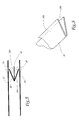
- These means drives are associated with deflection rollers 34 so as to position the sheets 22 and 24 one above on the other, while means 36 of conformation are able to fold the band 26 back on itself as shown in Figure 3, and direct the tape as well folded between sheets 22 and 24.
- the machine 20 is equipped with welding means 38 comprising a crew upper 40 and lower crew 42 between which the sheets 22 and 24 and strip 26 are intended to be positioned. More specifically, the facing faces of these crews 40 and 42 carry welding jaws complementary which, when they enclose each other two layers of polyolefin, cause their fusion localized and thus their welding.
- welding jaws complementary which, when they enclose each other two layers of polyolefin, cause their fusion localized and thus their welding.
- Various techniques of welding are possible at these jaws, including thermal welding or welding techniques by ultrasound.
- these jaws are coated with a non-stick product vis-à-vis polyolefins.
- these jaws carry reliefs adapted to form decorations for the surfaces of the welds obtained.
- These welding jaws are also provided elements for pre-cutting sheets 22 and 24, adapted for, when applying these jaws, cut the plastic material on the outer periphery of the welds performed.
- the outline of the jaws of welding i.e. the areas of the jaws intended for enclose and melt the sheets 22 and 24 and the strip 26, conditions the course of the welds and therefore the shape outside of the pocket. Different pouch shapes can therefore be considered by changing only the welding footprint of the jaws.
- strip 44 made of a thermally conductive, flexible and non-stick material vis-à-vis polyolefins, in particular vis-à-vis polypropylene.
- band 44 is formed of a single layer of polyester or polyimide, thickness less than 25 ⁇ m.
- the strip 44 could also be made of any other material with thermal conduction characteristics allowing the assembly of the sheets 22 and 26, on the one hand, 24 and 26, on the other hand, as well as incompatibility in welding and / or when bonding with polypropylene at temperatures used.
- the machine 20 is equipped for this purpose with means 46 of conformation of the strip 44, adapted to insert this strip between the folds 26a and 26b of the strip 26.
- These means of conformation 46 are partially detailed in FIG. 4 and comprise a rigid plate 48. More specifically, this plate defines a path C of conformation generally in Z shape shown in phantom in Figure 4, following which the thermally conductive strip 44 passes, at the input of the plate, from an external position to the folds of the strip 26, at the exit of this plate, a position in which the strip 44 is interposed between the folds 26a and 26b of strip 26.
- the trajectory of conformation C extends at the inlet and outlet of the plate 48 in respective parallel directions and offset perpendicular to the direction band drive 26.
- the shaping means 46 are associated with means 50 for recovering the strip 44, arranged downstream welding means 38 and comprising a plate conformation 52 substantially similar to plate 48 adapted to release the strip 44 towards the outside following a direction transverse to the direction of movement F.
- these recovery means 50 comprise further a series of deflection rollers 54 capable of return the strip 44 to the input of the plate 48 in order to rotate the tape in closed cycle.
- the strip 44 is intended to be stored, for example example by winding, at the outlet of the release plate 52. Once the coil is full, it can be mounted at proximity of the plate 48 to supply the means 16.
- the operation of the machine 20 is as follows: On feeds machine 20 with both sheets 22 and 24 and bands 26 and 44, these various elements being trained sequentially.
- the conformation means 36 and 46 bring the strips 26 and 44 respectively between the sheets 22 and 24 so as to form at the input welding means 38, the structure of Figure 5. More specifically, the slice free of the fold 26a of the strip 26 is arranged just at the vertical alignment of the sheet 22 at a weld zone 56, the free edge of the fold 26b is arranged just below the lower sheet 24 at a weld zone 58 and the strip 44 is interposed between these folds 26a and 26b and these areas to be welded 56 and 58.
- the thermally conductive strip 44 ensures heat conduction at the areas to be welded 56 and 58, with a view to carrying out the welds 8 and 10 of the pocket 1.
- the strip 44 being made of a material non-stick vis-à-vis polypropylene, welds 8 and 10 do not adhere to the strip 44.
- the material constituting this strip is flexible enough to allow the transfer of marking efforts by reliefs of the jaws, in order to form along the welds 8 and 10 the aforementioned decorative imitations.
- the welding jaws cause the formation of the lateral welds 12 and pre-cut the sheets 22 and 24 all around the welds made.
- the means of recovery 50 release the tape 44 and return it to entry of the shaping means 46, as represented by the arrows F ′, the path of the strip 44 between these arrows being omitted for clarity of the drawing.
- the pouch 1 thus obtained only has to be torn from the rest of sheets 22 and 24, this operation being facilitated by the pre-cuts made during the application of the welding jaws.
- the manufacturing machine 20 thus makes it possible to obtain quickly the polypropylene pouch 1 of FIG. 1, the welding means 38 simultaneously forming the welds 8, 10 and 12. Compared to machines for manufacturing known polypropylene sachets, bring are inexpensive and relate mainly to shaping means 36 and 46 and the welding means 38.
- the welding jaws have advantageously a stepped profile so that they homogeneously weld areas with two thicknesses of polypropylene sheet to form the welds 12 and areas with four sheet / strip thicknesses in polypropylene and a strip thickness 44 to form welds 8 and 10.
- the height separating the faces of welding of the precut edges is modified by corresponding way.
- FIGs 6 to 8 are shown variants of polypropylene pouches according to the invention.
- a pocket 1 similar to that of FIG. 1 except in its part opposite to the bellows 6.
- the closing flap 16 is replaced by a reinforcement pediment 16 'welded directly to the walls front 2 and rear 4 of the pocket so as to close these one on top of the other.
- this pediment 16 ' is provided with a perforation in order to suspend the pocket 1, especially during its marketing.
- the pocket 1 of FIG. 7 combines the flap of closure 16 of the pocket of FIG. 1 and the pediment of reinforcement 16 'of the pouch of FIG. 6.
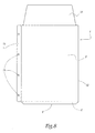
- Figure 8 a pocket in polypropylene 1 more particularly intended for filing documents.
- the pocket of Figure 8 includes the same structural elements as the cover of the figure 1, referenced by the same numbers, and is further provided, at one of its lateral welds 12, a strip reinforcement 18. This strip is provided with a series of perforations 19 intended to receive the rings of a workbook.
- the pouch according to the invention does not not necessarily have only one bellows.
Applications Claiming Priority (2)
| Application Number | Priority Date | Filing Date | Title |
|---|---|---|---|
| FR0306329 | 2003-05-26 | ||
| FR0306329A FR2855453B1 (fr) | 2003-05-26 | 2003-05-26 | Procede et machine de fabrication d'une pochette d'emballage et pochette obtenue par ce procede |
Publications (1)
| Publication Number | Publication Date |
|---|---|
| EP1481912A1 true EP1481912A1 (de) | 2004-12-01 |
Family
ID=33104476
Family Applications (1)
| Application Number | Title | Priority Date | Filing Date |
|---|---|---|---|
| EP04356080A Withdrawn EP1481912A1 (de) | 2003-05-26 | 2004-05-26 | Verpackungsbeutel und Verfahren und Vorrichtung zur dessen Herstellung |
Country Status (2)
| Country | Link |
|---|---|
| EP (1) | EP1481912A1 (de) |
| FR (1) | FR2855453B1 (de) |
Citations (9)
| Publication number | Priority date | Publication date | Assignee | Title |
|---|---|---|---|---|
| GB859160A (en) * | 1956-10-02 | 1961-01-18 | Plastus Sa | Improvements in bags and the like and their methods of production |
| FR2417440A1 (fr) * | 1978-02-15 | 1979-09-14 | Vittel Eaux Min | Recipients en matiere synthetique |
| FR2660896A1 (fr) * | 1990-03-26 | 1991-10-18 | Juttet Michel | Porte-document a index integre. |
| FR2752414A1 (fr) * | 1996-08-14 | 1998-02-20 | Thimonnier Sa | Emballage souple pour le conditionnement de produits liquides ou visqueux |
| FR2765518A1 (fr) * | 1997-07-02 | 1999-01-08 | Gilbert Capy | Procede de fabrication d'un conteneur a base de papier |
| GB2335652A (en) * | 1998-03-27 | 1999-09-29 | Pfankuch Maschinen Gmbh | Bag with adhesive closure strip |
| FR2784621A1 (fr) * | 1998-10-20 | 2000-04-21 | Viquel | Pochette a soufflet pour le rangement et/ou le classement de documents |
| EP1211061A2 (de) * | 2000-11-30 | 2002-06-05 | Illinois Tool Works Inc. | Verfahren zur Herstellung von Seitenfaltenbeuteln |
| US6425847B1 (en) * | 1999-03-08 | 2002-07-30 | Klaus Reinhold Maschinen-Und Geraetebau Gmbh | Method for producing a packing material from plastic film or a similar weldable material |
-
2003
- 2003-05-26 FR FR0306329A patent/FR2855453B1/fr not_active Expired - Fee Related
-
2004
- 2004-05-26 EP EP04356080A patent/EP1481912A1/de not_active Withdrawn
Patent Citations (9)
| Publication number | Priority date | Publication date | Assignee | Title |
|---|---|---|---|---|
| GB859160A (en) * | 1956-10-02 | 1961-01-18 | Plastus Sa | Improvements in bags and the like and their methods of production |
| FR2417440A1 (fr) * | 1978-02-15 | 1979-09-14 | Vittel Eaux Min | Recipients en matiere synthetique |
| FR2660896A1 (fr) * | 1990-03-26 | 1991-10-18 | Juttet Michel | Porte-document a index integre. |
| FR2752414A1 (fr) * | 1996-08-14 | 1998-02-20 | Thimonnier Sa | Emballage souple pour le conditionnement de produits liquides ou visqueux |
| FR2765518A1 (fr) * | 1997-07-02 | 1999-01-08 | Gilbert Capy | Procede de fabrication d'un conteneur a base de papier |
| GB2335652A (en) * | 1998-03-27 | 1999-09-29 | Pfankuch Maschinen Gmbh | Bag with adhesive closure strip |
| FR2784621A1 (fr) * | 1998-10-20 | 2000-04-21 | Viquel | Pochette a soufflet pour le rangement et/ou le classement de documents |
| US6425847B1 (en) * | 1999-03-08 | 2002-07-30 | Klaus Reinhold Maschinen-Und Geraetebau Gmbh | Method for producing a packing material from plastic film or a similar weldable material |
| EP1211061A2 (de) * | 2000-11-30 | 2002-06-05 | Illinois Tool Works Inc. | Verfahren zur Herstellung von Seitenfaltenbeuteln |
Also Published As
| Publication number | Publication date |
|---|---|
| FR2855453B1 (fr) | 2006-09-15 |
| FR2855453A1 (fr) | 2004-12-03 |
Similar Documents
| Publication | Publication Date | Title |
|---|---|---|
| EP2035288B1 (de) | Plastikbeutel mit öffnungen für lebensmittelprodukte und verfahren zu seiner herstellung | |
| BE1001678A4 (fr) | Recipient refermable en film mince, notamment sac d'emballage, et son procede de fabrication. | |
| EP0746507B1 (de) | Dichtes behältnis, insbesondere schlauchbeutel, verfahren zu seiner herstellung, verfahren zu seiner befüllung mit einer flüssigkeit | |
| EP0906866A1 (de) | Verfahren und Maschine zum automatischen Herstellen von Beuteln, sowie die so erhaltenen Beutel | |
| FR2464201A1 (fr) | Sac pour l'emballage sous vide de viande ou produits similaires | |
| EP1675789B1 (de) | Beutel mit elastischem band und verfahren zu dessen herstellung | |
| WO2003045816A2 (fr) | Emballage a ouverture par dechirure orientee | |
| EP1387792B1 (de) | Verfahren und vorrichtung zum herstellen von beuteln mit von einem schieber betätigbaren schliessprofilen , und erzeugte beutel | |
| EP2039619B1 (de) | Herstellungsverfahren eines Beutels aus einer Plastikfolienrolle | |
| FR2586650A1 (fr) | Sacs, produit de base, procede et machine pour les fabriquer | |
| EP0976539A1 (de) | Verfahren und Vorrichtung zur Herstellung von Beuteln mit flachem Boden | |
| FR3093705A1 (fr) | Sac d’emballage à recyclage facilité, et procédé de fabrication en continu d’une pluralité de sacs de ce type | |
| EP1481912A1 (de) | Verpackungsbeutel und Verfahren und Vorrichtung zur dessen Herstellung | |
| EP0416063B1 (de) | Tragetasche mit in den verstärkungsbereichen ausgeschnittenen grifflöchern sowie verfahren und vorrichtung zu ihrer herstellung | |
| EP3277596B1 (de) | Verfahren zur kontinuierlichen herstellung eines kunststoffbeutels für nahrungsmittel | |
| EP1299292B1 (de) | Verpackung für empfindliche güter und verfahren zur herstellung | |
| EP0500428B1 (de) | Bag-in-Box mit automatisch auffaltbarem Boden und Verfahren zu deren Herstellung | |
| FR2926067A1 (fr) | Un sac integrant une bande d'arrachage et une poignee | |
| BE1008390A6 (fr) | Sac souple et procede de realisation de celui-ci. | |
| EP3250465B1 (de) | Verfahren zur bereitstellung eines beutels mit starrem rahmen | |
| FR2777548A1 (fr) | Feuille d'emballage et sachet d'emballage la comportant | |
| FR2757484A1 (fr) | Enceinte etanche et procede de fabrication d'une ebauche d'enceinte etanche | |
| FR2867454A1 (fr) | Sac se transformant en un sac de plus grande contenance | |
| FR2595295A1 (fr) | Feuille stratifiee, notamment pour emballage | |
| FR2717349A1 (fr) | Article coiffant jetable du genre charlotte ronde. |
Legal Events
| Date | Code | Title | Description |
|---|---|---|---|
| PUAI | Public reference made under article 153(3) epc to a published international application that has entered the european phase |
Free format text: ORIGINAL CODE: 0009012 |
|
| AK | Designated contracting states |
Kind code of ref document: A1 Designated state(s): AT BE BG CH CY CZ DE DK EE ES FI FR GB GR HU IE IT LI LU MC NL PL PT RO SE SI SK TR |
|
| AX | Request for extension of the european patent |
Extension state: AL HR LT LV MK |
|
| 17P | Request for examination filed |
Effective date: 20050409 |
|
| AKX | Designation fees paid |
Designated state(s): AT BE BG CH CY CZ DE DK EE ES FI FR GB GR HU IE IT LI LU MC NL PL PT RO SE SI SK TR |
|
| AXX | Extension fees paid |
Extension state: LV Payment date: 20050409 Extension state: LT Payment date: 20050409 Extension state: HR Payment date: 20050409 |
|
| STAA | Information on the status of an ep patent application or granted ep patent |
Free format text: STATUS: THE APPLICATION HAS BEEN WITHDRAWN |
|
| 18W | Application withdrawn |
Effective date: 20060626 |