EP1481912A1 - Packaging bag and its method and device of manufacture - Google Patents
Packaging bag and its method and device of manufacture Download PDFInfo
- Publication number
- EP1481912A1 EP1481912A1 EP04356080A EP04356080A EP1481912A1 EP 1481912 A1 EP1481912 A1 EP 1481912A1 EP 04356080 A EP04356080 A EP 04356080A EP 04356080 A EP04356080 A EP 04356080A EP 1481912 A1 EP1481912 A1 EP 1481912A1
- Authority
- EP
- European Patent Office
- Prior art keywords
- sheets
- welding
- strip
- polypropylene
- welded
- Prior art date
- Legal status (The legal status is an assumption and is not a legal conclusion. Google has not performed a legal analysis and makes no representation as to the accuracy of the status listed.)
- Withdrawn
Links
Images


Classifications
-
- B—PERFORMING OPERATIONS; TRANSPORTING
- B65—CONVEYING; PACKING; STORING; HANDLING THIN OR FILAMENTARY MATERIAL
- B65D—CONTAINERS FOR STORAGE OR TRANSPORT OF ARTICLES OR MATERIALS, e.g. BAGS, BARRELS, BOTTLES, BOXES, CANS, CARTONS, CRATES, DRUMS, JARS, TANKS, HOPPERS, FORWARDING CONTAINERS; ACCESSORIES, CLOSURES, OR FITTINGS THEREFOR; PACKAGING ELEMENTS; PACKAGES
- B65D33/00—Details of, or accessories for, sacks or bags
- B65D33/14—Suspension means
-
- B—PERFORMING OPERATIONS; TRANSPORTING
- B65—CONVEYING; PACKING; STORING; HANDLING THIN OR FILAMENTARY MATERIAL
- B65D—CONTAINERS FOR STORAGE OR TRANSPORT OF ARTICLES OR MATERIALS, e.g. BAGS, BARRELS, BOTTLES, BOXES, CANS, CARTONS, CRATES, DRUMS, JARS, TANKS, HOPPERS, FORWARDING CONTAINERS; ACCESSORIES, CLOSURES, OR FITTINGS THEREFOR; PACKAGING ELEMENTS; PACKAGES
- B65D75/00—Packages comprising articles or materials partially or wholly enclosed in strips, sheets, blanks, tubes, or webs of flexible sheet material, e.g. in folded wrappers
- B65D75/008—Standing pouches, i.e. "Standbeutel"
-
- B—PERFORMING OPERATIONS; TRANSPORTING
- B31—MAKING ARTICLES OF PAPER, CARDBOARD OR MATERIAL WORKED IN A MANNER ANALOGOUS TO PAPER; WORKING PAPER, CARDBOARD OR MATERIAL WORKED IN A MANNER ANALOGOUS TO PAPER
- B31B—MAKING CONTAINERS OF PAPER, CARDBOARD OR MATERIAL WORKED IN A MANNER ANALOGOUS TO PAPER
- B31B2155/00—Flexible containers made from webs
- B31B2155/002—Flexible containers made from webs by joining superimposed webs, e.g. with separate bottom webs
-
- B—PERFORMING OPERATIONS; TRANSPORTING
- B31—MAKING ARTICLES OF PAPER, CARDBOARD OR MATERIAL WORKED IN A MANNER ANALOGOUS TO PAPER; WORKING PAPER, CARDBOARD OR MATERIAL WORKED IN A MANNER ANALOGOUS TO PAPER
- B31B—MAKING CONTAINERS OF PAPER, CARDBOARD OR MATERIAL WORKED IN A MANNER ANALOGOUS TO PAPER
- B31B2160/00—Shape of flexible containers
- B31B2160/20—Shape of flexible containers with structural provision for thickness of contents
Definitions
- the present invention relates to a method of manufacture of a bellows packaging pouch, single-layer polypropylene.
- the invention also relates to a machine for manufacturing such a packaging pouch and a polypropylene pouch thus produced.
- plastics capable of being welded joints fall into two categories.
- materials with a polar molecular structure such as polyvinyl chloride (PVC) are used for several years, being generally welded by high frequency welding processes. Welding these materials provide reliable, aesthetic and opening the way to the most complex assemblies, in particular for the production of bellows or multiple pockets.
- non-polar molecular materials such as polyolefins including polyethylene and polypropylene, which, due to their structure, do not allow high frequency welding but support processes heat input welding, such as thermal welding, ultrasonic, pulse, etc. These welds remain however difficult to shape and are aesthetically pleasing not very attractive.
- PVC has the disadvantage of emit harmful emissions for its disposal the environment. This environmental constraint prompted plastic packaging manufacturers in propose alternative solutions, in particular based on polyolefin whose recycling is easier and less pollutant.
- bellows made of polyethylene, which are made a single sheet of single-layer plastic, folded over itself so as to form at the level of its fold a bellows.
- the two ends of the bellows, according to its length, are clamped by side welds so that the bellows cannot extend over its entire length.
- the sachets obtained have a not very attractive appearance in reason, on the one hand, for unsightly side welds and, on the other hand, excessive tensions of the material plastic at the pinches of the ends of the bellows.
- US-B-6,425,847 proposes to produce a pocket, possibly in polypropylene or from multi-layer films, three of whose sides are each provided with a bellows, the fourth side being left free yawning. Welding the folds of these bellows to the walls front cover is not described in this document and a priori only requires the application of matrices of overlapping welding, which suggests that the pocket mentioned above can only be made by using complex multi-layer films with only one single weldable face.
- the purpose of the present invention is to provide a method of manufacturing a packaging pouch bellows and single-layer polypropylene, which, while using an easily recyclable material, guarantees obtaining an aesthetic pouch to enhance the contents of this pocket.
- the subject of the invention is a method of manufacture of a packaging pouch, as defined in claim 1.
- the method according to the invention makes it possible to obtain quickly polypropylene packaging pouches provided with one or more bellows which open onto their entire length and thus more attractive aesthetic.
- the process is easily industrializable and does not require no costly layout compared to processes existing.
- it is reliable and uses only materials whose elimination is not polluting or which are easily recyclable.
- the invention further relates to a machine for manufacture of a packaging pouch, allowing implementing the method mentioned above, as defined to claim 10.
- the invention also relates to a pocket obtained by the process or the machine defined above, as defined in claim 16.
- the pouch according to the invention thus has one or more several bellows which deploy over their entire length, allowing for example the pouch to hold standing.
- the welding of only two layers of material in polypropylene all around the pouch allows formation of larger welds and prevents the formation of residual stresses of the plastic, both at bellows level as side walls.
- FIG. 1 a pocket 1 in polypropylene.
- This pocket has two walls front, namely a front wall 2 (the wall turned towards the reader in FIG. 1) and a rear wall 4.
- the pocket 1 also has a bottom wall in the form a foldable bellows 6 connecting the walls 2 and 4 at the level from one side. More specifically, the bellows 6 is fixed on the one hand, to the front wall 2 by a weld 8 and, on the other hand, to the rear wall 4 by a weld 10. When the bellows 6 is deployed or opened, the pocket 1 is able to stand on a flat surface on which rests the bellows 6.
- Walls 2 and 4 are also directly connected to each other by two lateral welds 12 which extend at two opposite sides of these walls, from the junction points 14 of the welds 8 and 10.
- the bellows 6 is not, at its ends according to its length, pinched by welds extending so rectilinear the lateral welds 12.
- these bellows ends 6 are connected to the front walls 2 and rear 4 by respective parts of the welds 8 and 10 separate from the welds 12, allowing the bellows to be deployed over its entire length.
- the walls 2 and 4 and the bellows 6 are formed a single layer of polypropylene, for example thick about 120 ⁇ m.
- the rear wall 4 is advantageously provided with a closing flap 16 adapted to cover the side of the front wall 2 opposite the bellows 6. So optional, the face of this flap intended to come is press against the front wall 2 is coated with a material adhesive, possibly adapted to allow opening and to close the flap 16 at will.
- the different welds 8, 10 and 12 thus connect only two layers of plastic, which allows easily obtain welds with a width that can reach a few millimeters and presenting advantageously decoration patterns, such as imitations of stitching.
- a manufacturing machine 20 schematically shown in Figure 2.
- This machine is adapted to be fed by a sheet single-layer polypropylene 22 called upper (shown in the upper part of Figure 2) intended to constitute the front wall 2 of the pocket 1, a sheet single layer of polypropylene 24 called lower intended for constitute the rear wall 4 of this pocket, and a single-layer polypropylene strip 26 intended to form the bellows 6.
- the machine 20 for this purpose comprises means sequential drive sheets 22 and 24 and the strip 26, which move the sheets and the strip according to the arrows F.
- These means known per se, are not shown in Figure 2.
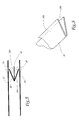
- These means drives are associated with deflection rollers 34 so as to position the sheets 22 and 24 one above on the other, while means 36 of conformation are able to fold the band 26 back on itself as shown in Figure 3, and direct the tape as well folded between sheets 22 and 24.
- the machine 20 is equipped with welding means 38 comprising a crew upper 40 and lower crew 42 between which the sheets 22 and 24 and strip 26 are intended to be positioned. More specifically, the facing faces of these crews 40 and 42 carry welding jaws complementary which, when they enclose each other two layers of polyolefin, cause their fusion localized and thus their welding.
- welding jaws complementary which, when they enclose each other two layers of polyolefin, cause their fusion localized and thus their welding.
- Various techniques of welding are possible at these jaws, including thermal welding or welding techniques by ultrasound.
- these jaws are coated with a non-stick product vis-à-vis polyolefins.
- these jaws carry reliefs adapted to form decorations for the surfaces of the welds obtained.
- These welding jaws are also provided elements for pre-cutting sheets 22 and 24, adapted for, when applying these jaws, cut the plastic material on the outer periphery of the welds performed.
- the outline of the jaws of welding i.e. the areas of the jaws intended for enclose and melt the sheets 22 and 24 and the strip 26, conditions the course of the welds and therefore the shape outside of the pocket. Different pouch shapes can therefore be considered by changing only the welding footprint of the jaws.
- strip 44 made of a thermally conductive, flexible and non-stick material vis-à-vis polyolefins, in particular vis-à-vis polypropylene.
- band 44 is formed of a single layer of polyester or polyimide, thickness less than 25 ⁇ m.
- the strip 44 could also be made of any other material with thermal conduction characteristics allowing the assembly of the sheets 22 and 26, on the one hand, 24 and 26, on the other hand, as well as incompatibility in welding and / or when bonding with polypropylene at temperatures used.
- the machine 20 is equipped for this purpose with means 46 of conformation of the strip 44, adapted to insert this strip between the folds 26a and 26b of the strip 26.
- These means of conformation 46 are partially detailed in FIG. 4 and comprise a rigid plate 48. More specifically, this plate defines a path C of conformation generally in Z shape shown in phantom in Figure 4, following which the thermally conductive strip 44 passes, at the input of the plate, from an external position to the folds of the strip 26, at the exit of this plate, a position in which the strip 44 is interposed between the folds 26a and 26b of strip 26.
- the trajectory of conformation C extends at the inlet and outlet of the plate 48 in respective parallel directions and offset perpendicular to the direction band drive 26.
- the shaping means 46 are associated with means 50 for recovering the strip 44, arranged downstream welding means 38 and comprising a plate conformation 52 substantially similar to plate 48 adapted to release the strip 44 towards the outside following a direction transverse to the direction of movement F.
- these recovery means 50 comprise further a series of deflection rollers 54 capable of return the strip 44 to the input of the plate 48 in order to rotate the tape in closed cycle.
- the strip 44 is intended to be stored, for example example by winding, at the outlet of the release plate 52. Once the coil is full, it can be mounted at proximity of the plate 48 to supply the means 16.
- the operation of the machine 20 is as follows: On feeds machine 20 with both sheets 22 and 24 and bands 26 and 44, these various elements being trained sequentially.
- the conformation means 36 and 46 bring the strips 26 and 44 respectively between the sheets 22 and 24 so as to form at the input welding means 38, the structure of Figure 5. More specifically, the slice free of the fold 26a of the strip 26 is arranged just at the vertical alignment of the sheet 22 at a weld zone 56, the free edge of the fold 26b is arranged just below the lower sheet 24 at a weld zone 58 and the strip 44 is interposed between these folds 26a and 26b and these areas to be welded 56 and 58.
- the thermally conductive strip 44 ensures heat conduction at the areas to be welded 56 and 58, with a view to carrying out the welds 8 and 10 of the pocket 1.
- the strip 44 being made of a material non-stick vis-à-vis polypropylene, welds 8 and 10 do not adhere to the strip 44.
- the material constituting this strip is flexible enough to allow the transfer of marking efforts by reliefs of the jaws, in order to form along the welds 8 and 10 the aforementioned decorative imitations.
- the welding jaws cause the formation of the lateral welds 12 and pre-cut the sheets 22 and 24 all around the welds made.
- the means of recovery 50 release the tape 44 and return it to entry of the shaping means 46, as represented by the arrows F ′, the path of the strip 44 between these arrows being omitted for clarity of the drawing.
- the pouch 1 thus obtained only has to be torn from the rest of sheets 22 and 24, this operation being facilitated by the pre-cuts made during the application of the welding jaws.
- the manufacturing machine 20 thus makes it possible to obtain quickly the polypropylene pouch 1 of FIG. 1, the welding means 38 simultaneously forming the welds 8, 10 and 12. Compared to machines for manufacturing known polypropylene sachets, bring are inexpensive and relate mainly to shaping means 36 and 46 and the welding means 38.
- the welding jaws have advantageously a stepped profile so that they homogeneously weld areas with two thicknesses of polypropylene sheet to form the welds 12 and areas with four sheet / strip thicknesses in polypropylene and a strip thickness 44 to form welds 8 and 10.
- the height separating the faces of welding of the precut edges is modified by corresponding way.
- FIGs 6 to 8 are shown variants of polypropylene pouches according to the invention.
- a pocket 1 similar to that of FIG. 1 except in its part opposite to the bellows 6.
- the closing flap 16 is replaced by a reinforcement pediment 16 'welded directly to the walls front 2 and rear 4 of the pocket so as to close these one on top of the other.
- this pediment 16 ' is provided with a perforation in order to suspend the pocket 1, especially during its marketing.
- the pocket 1 of FIG. 7 combines the flap of closure 16 of the pocket of FIG. 1 and the pediment of reinforcement 16 'of the pouch of FIG. 6.
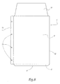
- Figure 8 a pocket in polypropylene 1 more particularly intended for filing documents.
- the pocket of Figure 8 includes the same structural elements as the cover of the figure 1, referenced by the same numbers, and is further provided, at one of its lateral welds 12, a strip reinforcement 18. This strip is provided with a series of perforations 19 intended to receive the rings of a workbook.
- the pouch according to the invention does not not necessarily have only one bellows.
Abstract
Description
La présente invention concerne un procédé de fabrication d'une pochette d'emballage à soufflet, en polypropylène mono-couche. L'invention a également trait à une machine de fabrication d'une telle pochette d'emballage et à une pochette en polypropylène ainsi fabriquée.The present invention relates to a method of manufacture of a bellows packaging pouch, single-layer polypropylene. The invention also relates to a machine for manufacturing such a packaging pouch and a polypropylene pouch thus produced.
Dans le domaine des sacs ou sachets d'emballage en film plastique souple, les matières plastiques aptes à être assemblées par soudage se divisent en deux catégories. D'une part, les matières à structure moléculaire polaire, telles que le polychlorure de vinyle (PVC), sont utilisées depuis plusieurs années, en étant généralement soudées par des procédés de soudage à haute fréquence. Le soudage de ces matières fournit des soudures fiables, esthétiques et ouvrant libre champ aux assemblages les plus complexes, notamment en vue de fabriquer des sachets à soufflets ou à poches multiples. D'autre part, on utilise également des matières à structure moléculaire non polaire, telles que les polyoléfines dont le polyéthylène et le polypropylène, qui, en raison de leur structure, n'autorisent pas le soudage à haute fréquence mais supportent des procédés de soudage à apport de chaleur, tels que le soudage thermique, à ultra-sons, à impulsions, etc. Ces soudures restent cependant difficiles à façonner et sont d'une esthétique peu avenante.In the field of packaging bags or sachets in flexible plastic film, plastics capable of being welded joints fall into two categories. On the one hand, materials with a polar molecular structure, such as polyvinyl chloride (PVC), are used for several years, being generally welded by high frequency welding processes. Welding these materials provide reliable, aesthetic and opening the way to the most complex assemblies, in particular for the production of bellows or multiple pockets. On the other hand, we also use non-polar molecular materials, such as polyolefins including polyethylene and polypropylene, which, due to their structure, do not allow high frequency welding but support processes heat input welding, such as thermal welding, ultrasonic, pulse, etc. These welds remain however difficult to shape and are aesthetically pleasing not very attractive.
Par ailleurs, le PVC présente l'inconvénient de dégager lors de son élimination des émissions nocives pour l'environnement. Cette contrainte environnementale a incité les industriels de l'emballage en matière plastique à proposer des solutions alternatives, notamment à base de polyoléfine dont le recyclage est plus facile et moins polluant.Furthermore, PVC has the disadvantage of emit harmful emissions for its disposal the environment. This environmental constraint prompted plastic packaging manufacturers in propose alternative solutions, in particular based on polyolefin whose recycling is easier and less pollutant.
A cet effet, il existe actuellement des sachets à soufflet, réalisés en polyéthylène, qui sont constitués d'une unique feuille de plastique mono-couche, repliée sur elle-même de manière à former au niveau de son pli un soufflet. Les deux extrémités du soufflet, suivant sa longueur, sont pincées par des soudures latérales de sorte que le soufflet ne peut se déployer sur toute sa longueur. Les sachets obtenus présentent un aspect peu avenant en raison, d'une part, des soudures latérales peu esthétiques et, d'autre part, de tensions excessives de la matière plastique au niveau des pincements des extrémités du soufflet.For this purpose, there are currently sachets with bellows, made of polyethylene, which are made a single sheet of single-layer plastic, folded over itself so as to form at the level of its fold a bellows. The two ends of the bellows, according to its length, are clamped by side welds so that the bellows cannot extend over its entire length. The sachets obtained have a not very attractive appearance in reason, on the one hand, for unsightly side welds and, on the other hand, excessive tensions of the material plastic at the pinches of the ends of the bellows.
Ce dernier inconvénient est parfois contourné en utilisant des films plastiques multicouches qui permettent de libérer le soufflet sur toute sa longueur. Cette solution a cependant pour inconvénient d'être coûteuse et de rendre difficile le recyclage des sachets du fait de l'utilisation conjointe de matériaux de natures différentes.This last drawback is sometimes overcome by using multilayer plastic films which allow to release the bellows over its entire length. This solution has the disadvantage of being expensive and make it difficult to recycle sachets due to the joint use of natural materials different.
US-B-6,425,847 propose de réaliser une pochette, éventuellement en polypropylène ou à partir de films multi-couches, dont trois des côtés sont pourvus chacun d'un soufflet, le quatrième côté étant laissé librement bâillant. Le soudage des plis de ces soufflets aux parois frontales de la pochette n'est pas décrit dans ce document et ne nécessite a priori que l'application de matrices de soudage superposées, ce qui laisse supposer que la pochette évoquée ci-dessus ne peut être fabriquée qu'en employant des films complexes multi-couches ne présentant qu'une seule face soudable.US-B-6,425,847 proposes to produce a pocket, possibly in polypropylene or from multi-layer films, three of whose sides are each provided with a bellows, the fourth side being left free yawning. Welding the folds of these bellows to the walls front cover is not described in this document and a priori only requires the application of matrices of overlapping welding, which suggests that the pocket mentioned above can only be made by using complex multi-layer films with only one single weldable face.
Le but de la présente invention est de proposer un procédé de fabrication d'une pochette d'emballage à soufflet et en polypropylène mono-couche, qui, tout en utilisant une matière facilement recyclable, garantit l'obtention d'une pochette esthétique en vue de valoriser le contenu de cette pochette. The purpose of the present invention is to provide a method of manufacturing a packaging pouch bellows and single-layer polypropylene, which, while using an easily recyclable material, guarantees obtaining an aesthetic pouch to enhance the contents of this pocket.
A cet effet, l'invention a pour objet un procédé de
fabrication d'une pochette d'emballage, tel que défini à la
revendication 1.To this end, the subject of the invention is a method of
manufacture of a packaging pouch, as defined in
Le procédé selon l'invention permet d'obtenir rapidement des pochettes d'emballage en polypropylène munies d'un ou de plusieurs soufflets qui s'ouvrent sur toute leur longueur et ainsi d'esthétique plus avenante. Le procédé est facilement industrialisable et ne nécessite aucun aménagement coûteux par rapport aux procédés existants. De plus, il est fiable et n'utilise que des matériaux dont l'élimination n'est pas polluante ou bien qui sont facilement recyclables.The method according to the invention makes it possible to obtain quickly polypropylene packaging pouches provided with one or more bellows which open onto their entire length and thus more attractive aesthetic. The process is easily industrializable and does not require no costly layout compared to processes existing. In addition, it is reliable and uses only materials whose elimination is not polluting or which are easily recyclable.
D'autres caractéristiques de ce procédé, prises
isolément ou selon toutes les combinaisons techniquement
possibles, sont énoncées aux revendications dépendantes 2 à
9.Other characteristics of this process, taken
individually or in any combination technically
possible, are set out in
L'invention a en outre pour objet une machine de fabrication d'une pochette d'emballage, permettant la mise en oeuvre du procédé mentionné ci-dessus, telle que définie à la revendication 10.The invention further relates to a machine for manufacture of a packaging pouch, allowing implementing the method mentioned above, as defined to claim 10.
D'autres caractéristiques de cette machine, prises isolément ou selon toutes les combinaisons techniquement possibles, sont énoncées aux revendication dépendantes 11 à 15.Other characteristics of this machine, taken individually or in any combination technically possible, are set out in dependent claims 11 to 15.
L'invention a également pour objet une pochette
obtenue par le procédé ou la machine défini ci-dessus,
telle que définie à la revendication 16.The invention also relates to a pocket
obtained by the process or the machine defined above,
as defined in
La pochette selon l'invention dispose ainsi d'un ou de plusieurs soufflets qui se déploient sur toute leur longueur, permettant par exemple à la pochette de tenir debout. Le soudage d'uniquement deux couches de matière en polypropylène sur tout le pourtour de la pochette permet la formation de soudures plus larges et évite la formation de tensions résiduelles de la matière plastique, tant au niveau du soufflet que des parois latérales.The pouch according to the invention thus has one or more several bellows which deploy over their entire length, allowing for example the pouch to hold standing. The welding of only two layers of material in polypropylene all around the pouch allows formation of larger welds and prevents the formation of residual stresses of the plastic, both at bellows level as side walls.
D'autres caractéristiques de cette pochette, prises
isolément ou selon toutes les combinaisons techniquement
possibles, sont énoncées aux revendications dépendantes 17
et 18.Other characteristics of this pouch, taken
individually or in any combination technically
possible, are set out in
L'invention sera mieux comprise à la lecture de la description qui va suivre, donnée uniquement à titre d'exemple et faite en se référant aux dessins, sur lesquels :
- la figure 1 est une vue en perspective d'une pochette d'emballage selon l'invention ;
- la figure 2 est une vue schématique en perspective d'une machine selon l'invention utilisée pour fabriquer la pochette de la figure 1 ;
- la figure 3 est une vue en perspective d'un détail d'une bande pliée en polypropylène utilisée dans la machine de la figure 2 ;
- la figure 4 est une vue en perspective et à plus grande échelle d'un détail de la machine de la figure 2 ;
- la figure 5 est une coupe schématique prise selon le plan V sur la figure 2 ;
- les figures 6 et 7 sont des vues analogues à la figure 1, de variantes de pochette selon l'invention ; et
- la figure 8 est une vue en élévation d'une autre variante de pochette selon l'invention.
- Figure 1 is a perspective view of a packaging pouch according to the invention;
- Figure 2 is a schematic perspective view of a machine according to the invention used to manufacture the pouch of Figure 1;
- Figure 3 is a perspective view of a detail of a folded polypropylene strip used in the machine of Figure 2;
- Figure 4 is a perspective view on a larger scale of a detail of the machine of Figure 2;
- Figure 5 is a schematic section taken along plane V in Figure 2;
- Figures 6 and 7 are views similar to Figure 1, of pouch variants according to the invention; and
- Figure 8 is an elevational view of another variant of a pouch according to the invention.
Sur la figure 1 est représentée une pochette 1 en
polypropylène. Cette pochette comporte deux parois
frontales, à savoir une paroi avant 2 (la paroi tournée
vers le lecteur sur la figure 1) et une paroi arrière 4. La
pochette 1 comporte également une paroi de fond sous forme
d'un soufflet pliable 6 reliant les parois 2 et 4 au niveau
d'un de leur côté. Plus précisément, le soufflet 6 est fixé
d'une part, à la paroi avant 2 par une soudure 8 et,
d'autre part, à la paroi arrière 4 par une soudure 10.
Lorsque le soufflet 6 est déployé ou ouvert, la pochette 1
est à même de tenir debout sur une surface plane sur
laquelle repose le soufflet 6.In Figure 1 is shown a
Les parois 2 et 4 sont également reliées directement
l'une à l'autre par deux soudures latérales 12 qui
s'étendent au niveau de deux côtés opposés de ces parois,
depuis les points de jonction 14 des soudures 8 et 10. A la
différence des sachets en polyoléfine de l'art antérieur,
le soufflet 6 n'est pas, à ses extrémités suivant sa
longueur, pincé par des soudures prolongeant de façon
rectiligne les soudures latérales 12. Au contraire, ces
extrémités du soufflets 6 sont reliées aux parois avant 2
et arrière 4 par des parties respectives des soudures 8 et
10 distinctes des soudures 12, ce qui permet au soufflet
d'être déployé sur toute sa longueur.
Les parois 2 et 4 et le soufflet 6 sont constitués
d'une mono-couche de polypropylène, par exemple d'épaisseur
d'environ 120 µm.The
La paroi arrière 4 est avantageusement munie d'un
rabat de fermeture 16 adapté pour recouvrir le côté de la
paroi frontale 2 opposé au soufflet 6. De manière
optionnelle, la face de ce rabat destinée à venir se
plaquer contre la paroi avant 2 est enduite d'une matière
adhésive, éventuellement adaptée pour permettre d'ouvrir et
de fermer le rabat 16 à volonté.The
Les différentes soudures 8, 10 et 12 relient ainsi
uniquement deux couches de matière plastique, ce qui permet
d'obtenir facilement des soudures d'une largeur pouvant
atteindre quelques millimètres et présentant
avantageusement des motifs de décoration, tels que des
imitations de points de couture. The
Pour obtenir la pochette 1, notamment les différentes
soudures 8, 10 et 12, on utilise une machine de fabrication
20 représentée schématiquement sur la figure 2. Cette
machine est adaptée pour être alimentée par une feuille
mono-couche en polypropylène 22 dite supérieure
(représentée dans la partie haute de la figure 2) destinée
à constituer la paroi avant 2 de la pochette 1, une feuille
mono-couche de polypropylène 24 dite inférieure destinée à
constituer la paroi arrière 4 de cette pochette, et une
bande mono-couche de polypropylène 26 destinée à former le
soufflet 6.To obtain the
La machine 20 comporte à cet effet des moyens
d'entraínement séquentiel des feuilles 22 et 24 et de la
bande 26, qui déplacent les feuilles et la bande selon les
flèches F. Ces moyens, connus en soi, ne sont pas
représentés sur la figure 2. A titre d'exemple, peuvent
être utilisés un coussin d'air, des rouleaux d'entraínement
ou une toile de KAPTON (marque déposée). Ces moyens
d'entraínement sont associés à des rouleaux de déflection
34 de façon à positionner les feuilles 22 et 24 l'une au-dessus
de l'autre, tandis que des moyens 36 de conformation
sont aptes à replier sur elle-même la bande 26 comme
représenté sur la figure 3, et à diriger la bande ainsi
pliée entre les feuilles 22 et 24.The
Pour réaliser les soudures 8, 10 et 12, la machine 20
est équipée de moyens de soudage 38 comportant un équipage
supérieur 40 et un équipage inférieur 42 entre lesquels les
feuilles 22 et 24 et la bande 26 sont destinées à être
positionnées. Plus précisément, les faces en regard de ces
équipages 40 et 42 portent des mâchoires de soudage
complémentaires qui, lorsqu'elles enserrent entre-elles
deux couches de polyoléfine, provoquent leur fusion
localisée et ainsi leur soudage. Diverses techniques de
soudage sont envisageables au niveau de ces mâchoires,
notamment des techniques de soudage thermique ou de soudage
par ultra-sons. Avantageusement, ces mâchoires sont
enduites d'un produit anti-adhérent vis-à-vis des
polyoléfines.To make the
De plus, ces mâchoires portent des reliefs complémentaires adaptés pour former des décors à la surfaces des soudures obtenues.In addition, these jaws carry reliefs adapted to form decorations for the surfaces of the welds obtained.
Ces mâchoires de soudage sont également munies
d'éléments de pré-découpe des feuilles 22 et 24, adaptés
pour, lors de l'application de ces mâchoires, couper la
matière plastique en périphérie extérieure des soudures
réalisées.These welding jaws are also provided
elements for
On comprend ainsi que le contour des mâchoires de
soudage, c'est-à-dire les zones des mâchoires destinées à
enserrer et faire fondre les feuilles 22 et 24 et la bande
26, conditionne le tracé des soudures et donc la forme
extérieure de la pochette. Différentes formes de pochette
peuvent donc être envisagées en changeant uniquement
l'empreinte de soudage des mâchoires.It is thus understood that the outline of the jaws of
welding, i.e. the areas of the jaws intended for
enclose and melt the
Pour permettre la formation simultanée des soudures 8
et 10 sensiblement alignées suivant la direction
d'application des mâchoires de soudage, il est prévu
d'alimenter la machine de fabrication 20 avec une bande 44
constituée d'un matériau thermo-conducteur, souple et anti-adhérent
vis-à-vis des polyoléfines, en particulier vis-à-vis
du polypropylène. A titre d'exemple, la bande 44 est
formée d'une mono-couche de polyester ou de polyimide,
d'épaisseur inférieure à 25 µm.To allow the simultaneous formation of
En variante, la bande 44 pourrait également être
constituée de tout autre matériau présentant des
caractéristiques de conduction thermique permettant
l'assemblage des feuilles 22 et 26, d'une part, 24 et 26,
d'autre part, ainsi qu'une incompatibilité au soudage et/ou
au collage avec le polypropylène aux températures
utilisées.Alternatively, the
La machine 20 est équipée à cet effet de moyens 46 de
conformation de la bande 44, adaptés pour insérer cette
bande entre les plis 26a et 26b de la bande 26. Ces moyens
de conformation 46 sont en partie détaillés sur la figure 4
et comportent une plaque rigide 48. Plus précisément, cette
plaque définit un trajet C de conformation globalement en
forme de Z figuré en traits mixtes sur la figure 4, suivant
lequel la bande thermo-conductrice 44 passe, en entrée de
la plaque, d'une position extérieure aux plis de la bande
26, à, en sortie de cette plaque, une position dans
laquelle la bande 44 est interposée entre les plis 26a et
26b de la bande 26. A cet effet, la trajectoire de
conformation C s'étend en entrée et en sortie de la plaque
48 suivant des directions respectives parallèles et
décalées selon une perpendiculaire à la direction
d'entraínement de la bande 26.The
Les moyens de conformation 46 sont associés à des
moyens 50 de récupération de la bande 44, disposés en aval
des moyens de soudure 38 et comprenant une plaque de
conformation 52 sensiblement analogue à la plaque 48
adaptée pour dégager la bande 44 vers l'extérieur suivant
une direction transversal au sens de déplacement F.
Avantageusement, ces moyens de récupération 50 comprennent
en outre une série de rouleaux de déflection 54 à même de
renvoyer la bande 44 en entrée de la plaque 48 afin de
faire tourner la bande en cycle fermé. En variante non-représentée,
la bande 44 est destinée à être stockée, par
exemple par bobinage, en sortie de la plaque de dégagement
52. Une fois la bobine pleine, celle-ci peut être montée à
proximité de la plaque 48 pour alimenter les moyens 16.The shaping means 46 are associated with
Le fonctionnement de la machine 20 est le suivant : On
alimente la machine 20 à la fois avec les feuilles 22 et 24
et les bandes 26 et 44, ces différents éléments étant
entraínés de manière séquentielle.The operation of the
Les moyens de conformation 36 et 46 amènent
respectivement les bandes 26 et 44 entre les feuilles 22 et
24 de façon à former en entrée des moyens de soudage 38, la
structure de la figure 5. Plus précisément, la tranche
libre du pli 26a de la bande 26 est disposée juste à
l'aplomb de la feuille 22 au niveau d'une zone à souder 56,
la tranche libre du pli 26b est disposé juste à l'aplomb de
la feuille inférieure 24 au niveau d'une zone à souder 58
et la bande 44 est interposée entre ces plis 26a et 26b et
ces zones à souder 56 et 58.The conformation means 36 and 46 bring
the
Cette structure est ensuite enserrée par les mâchoires
de soudage précitées. La bande thermo-conductrice 44 assure
la conduction de la chaleur au niveau des zones à souder 56
et 58, en vue de réaliser les soudures 8 et 10 de la
pochette 1. La bande 44 étant constituée d'un matériau
anti-adhérent vis-à-vis du polypropylène, les soudures 8 et
10 n'adhèrent pas à la bande 44. De plus, le matériau
constituant cette bande est suffisamment souple pour
permettre le transfert des efforts de marquage par les
reliefs des mâchoires, en vue de former le long des
soudures 8 et 10 les imitations décoratives précitées.
Simultanément, les mâchoires de soudage provoquent la
formation des soudures latérales 12 et pré-découpent les
feuilles 22 et 24 tout autour des soudures réalisées.This structure is then clamped by the jaws
welding aforementioned. The thermally
En sortie des moyens de soudage 38, les moyens de
récupération 50 dégagent la bande 44 et la renvoie en
entrée des moyens de conformation 46, comme représenté par
les flèches F', le trajet de la bande 44 entre ces flèches
étant omis pour la clarté du dessin.At the outlet of the welding means 38, the means of
La pochette 1 ainsi obtenue n'a plus qu'à être
déchenillée du reste des feuilles 22 et 24, cette opération
étant facilitée par les pré-découpes réalisées durant
l'application des mâchoires de soudage.The
La machine de fabrication 20 permet ainsi d'obtenir
rapidement la pochette en polypropylène 1 de la figure 1,
les moyens de soudage 38 formant simultanément les soudures
8, 10 et 12. Par rapport à des machines de fabrication de
sachets en polypropylène connues, les aménagements à
apporter sont peu coûteux et concernent essentiellement les
moyens de conformation 36 et 46 et les moyens de soudure
38.The
Par ailleurs, les mâchoires de soudage présentent
avantageusement un profil en gradin de façon à ce qu'elles
soudent de manière homogène des zones avec deux épaisseurs
de feuille en polypropylène pour former les soudures 12 et
des zones avec quatre épaisseurs de feuille/bande en
polypropylène et d'une épaisseur de bande 44 pour former
les soudures 8 et 10. La hauteur séparant les faces de
soudage des arêtes de pré-découpe s'en trouve modifiée de
manière correspondante.In addition, the welding jaws have
advantageously a stepped profile so that they
homogeneously weld areas with two thicknesses
of polypropylene sheet to form the
Sur les figures 6 à 8 sont représentées des variantes
de pochettes en polypropylène selon l'invention. Sur la
figure 6 est représentée une pochette 1 analogue à celle de
la figure 1 exceptée dans sa partie opposée au soufflet 6.
Plus précisément, le rabat de fermeture 16 est remplacé par
un fronton de renfort 16' soudé directement aux parois
avant 2 et arrière 4 de la pochette de manière à refermer
celles-ci l'une sur l'autre. Avantageusement, ce fronton
16' est pourvu d'une perforation en vue de suspendre la
pochette 1, notamment lors de sa commercialisation.In Figures 6 to 8 are shown variants
of polypropylene pouches according to the invention. On the
Figure 6 is shown a
La pochette 1 de la figure 7 combine le rabat de
fermeture 16 de la pochette de la figure 1 et le fronton de
renfort 16' de la pochette de la figure 6.The
Sur la figure 8 est représentée une pochette en
polypropylène 1 plus particulièrement destinée au
classement de documents. Bien que de géométrie et de
dimensions légèrement différentes de celles de la pochette
de la figure 1, la pochette de la figure 8 comporte les
mêmes éléments structurels que la pochette de la figure
1, référencés par les mêmes numéros, et est en outre munie,
au niveau d'une de ses soudures latérales 12, d'une bande
de renfort 18. Cette bande est pourvue d'une série de
perforations 19 destinées à recevoir les anneaux d'un
classeur.In Figure 8 is shown a pocket in
Divers aménagements et variantes aux pochettes,
machines et procédés décrits ci-dessus sont en outre
envisageables. En particulier, contrairement aux pochettes
des figures 1 et 6 à 8, la pochette selon l'invention ne
possède pas nécessairement qu'un seul soufflet. Au
contraire, il est envisageable de prévoir deux soufflets
latéraux en vis-à-vis et que les parois avant et arrière,
sur au moins un des côtés restant, soient reliées
directement l'une à l'autre par une soudure analogue aux
soudures 12.Various layouts and variants in the pockets,
machines and processes described above are further
conceivable. In particular, unlike the pockets
Figures 1 and 6 to 8, the pouch according to the invention does not
not necessarily have only one bellows. At
on the contrary, it is possible to envisage two bellows
facing each other and that the front and rear walls,
on at least one of the remaining sides, are connected
directly to each other by a weld similar to
Claims (18)
caractérisée en ce qu'elle comporte, d'une part, deux parois frontales (2, 4) en polypropylène soudées l'une à l'autre sur au moins un de leurs côtés et constitué de parties respectives des deux feuilles (22, 24) et, d'autre part, au moins un soufflet (6) en polypropylène reliant les deux parois sur un autre de leur côté et constitué d'une partie de la bande repliée (26) soudée auxdites parties des deux feuilles de façon à s'ouvrir sur sensiblement toute sa longueur.Packaging pouch obtained by the process according to any one of Claims 1 to 9,
characterized in that it comprises, on the one hand, two front walls (2, 4) of polypropylene welded to each other on at least one of their sides and consisting of respective parts of the two sheets (22, 24 ) and, on the other hand, at least one bellows (6) made of polypropylene connecting the two walls on another on their side and consisting of a part of the folded strip (26) welded to said parts of the two sheets so as to s '' open over substantially its entire length.
Applications Claiming Priority (2)
| Application Number | Priority Date | Filing Date | Title |
|---|---|---|---|
| FR0306329A FR2855453B1 (en) | 2003-05-26 | 2003-05-26 | METHOD AND MACHINE FOR MANUFACTURING A PACKAGING POUCH AND POUCH OBTAINED THEREBY |
| FR0306329 | 2003-05-26 |
Publications (1)
| Publication Number | Publication Date |
|---|---|
| EP1481912A1 true EP1481912A1 (en) | 2004-12-01 |
Family
ID=33104476
Family Applications (1)
| Application Number | Title | Priority Date | Filing Date |
|---|---|---|---|
| EP04356080A Withdrawn EP1481912A1 (en) | 2003-05-26 | 2004-05-26 | Packaging bag and its method and device of manufacture |
Country Status (2)
| Country | Link |
|---|---|
| EP (1) | EP1481912A1 (en) |
| FR (1) | FR2855453B1 (en) |
Citations (9)
| Publication number | Priority date | Publication date | Assignee | Title |
|---|---|---|---|---|
| GB859160A (en) * | 1956-10-02 | 1961-01-18 | Plastus Sa | Improvements in bags and the like and their methods of production |
| FR2417440A1 (en) * | 1978-02-15 | 1979-09-14 | Vittel Eaux Min | Free-standing containers of flexible thermoplastic film - with base creases welded to stabilised filled containers |
| FR2660896A1 (en) * | 1990-03-26 | 1991-10-18 | Juttet Michel | File incorporating an index tab |
| FR2752414A1 (en) * | 1996-08-14 | 1998-02-20 | Thimonnier Sa | Flexible packaging for pastes or liquids |
| FR2765518A1 (en) * | 1997-07-02 | 1999-01-08 | Gilbert Capy | Paper container fabrication method |
| GB2335652A (en) * | 1998-03-27 | 1999-09-29 | Pfankuch Maschinen Gmbh | Bag with adhesive closure strip |
| FR2784621A1 (en) * | 1998-10-20 | 2000-04-21 | Viquel | Pocket file with concertina pleats for storing/filing documents has anti-tear notches at upper ends of pleats |
| EP1211061A2 (en) * | 2000-11-30 | 2002-06-05 | Illinois Tool Works Inc. | Forming gusseted bags |
| US6425847B1 (en) * | 1999-03-08 | 2002-07-30 | Klaus Reinhold Maschinen-Und Geraetebau Gmbh | Method for producing a packing material from plastic film or a similar weldable material |
-
2003
- 2003-05-26 FR FR0306329A patent/FR2855453B1/en not_active Expired - Fee Related
-
2004
- 2004-05-26 EP EP04356080A patent/EP1481912A1/en not_active Withdrawn
Patent Citations (9)
| Publication number | Priority date | Publication date | Assignee | Title |
|---|---|---|---|---|
| GB859160A (en) * | 1956-10-02 | 1961-01-18 | Plastus Sa | Improvements in bags and the like and their methods of production |
| FR2417440A1 (en) * | 1978-02-15 | 1979-09-14 | Vittel Eaux Min | Free-standing containers of flexible thermoplastic film - with base creases welded to stabilised filled containers |
| FR2660896A1 (en) * | 1990-03-26 | 1991-10-18 | Juttet Michel | File incorporating an index tab |
| FR2752414A1 (en) * | 1996-08-14 | 1998-02-20 | Thimonnier Sa | Flexible packaging for pastes or liquids |
| FR2765518A1 (en) * | 1997-07-02 | 1999-01-08 | Gilbert Capy | Paper container fabrication method |
| GB2335652A (en) * | 1998-03-27 | 1999-09-29 | Pfankuch Maschinen Gmbh | Bag with adhesive closure strip |
| FR2784621A1 (en) * | 1998-10-20 | 2000-04-21 | Viquel | Pocket file with concertina pleats for storing/filing documents has anti-tear notches at upper ends of pleats |
| US6425847B1 (en) * | 1999-03-08 | 2002-07-30 | Klaus Reinhold Maschinen-Und Geraetebau Gmbh | Method for producing a packing material from plastic film or a similar weldable material |
| EP1211061A2 (en) * | 2000-11-30 | 2002-06-05 | Illinois Tool Works Inc. | Forming gusseted bags |
Also Published As
| Publication number | Publication date |
|---|---|
| FR2855453B1 (en) | 2006-09-15 |
| FR2855453A1 (en) | 2004-12-03 |
Similar Documents
| Publication | Publication Date | Title |
|---|---|---|
| EP2035288B1 (en) | Plastic bag with gussets for food products and its method of manufacture | |
| BE1001678A4 (en) | Container resealable thin film including bag packing, and manufacturing method thereof. | |
| EP0746507B1 (en) | Sealed envelope, particularly tubular bag, method for the manufacture thereof, and method for filling said envelope with a beverage | |
| EP0906866A1 (en) | Method and machine for the automatic manufacture of bags, as well as the bags thus obtained | |
| FR2464201A1 (en) | BAG FOR VACUUM PACKAGING OF MEAT OR SIMILAR PRODUCTS | |
| EP1675789B1 (en) | Bag having an elastic band, and method for the production thereof | |
| WO2003045816A2 (en) | Package, such as a bag, with oriented tear-opening | |
| EP1387792B1 (en) | Method for making bags comprising slider-actuated closure profiles, manufacturing machine and resulting bags | |
| EP2039619B1 (en) | Method of manufacturing a bag using a reel of film made from plastic material | |
| FR2888571A1 (en) | Food product e.g. melted cheese, packaging package making element, has sheet with tears guiding strips comprising respective ends heat-sealed on sheet for forming single pull tab spaced laterally from median axis | |
| FR2586650A1 (en) | Bags, starting material, and process and machine for manufacturing them | |
| EP0976539A1 (en) | Method and machine for preparing flat-bottom bags | |
| FR3093705A1 (en) | Easy-to-recycle packaging bag, and method of continuously manufacturing a plurality of such bags | |
| EP1481912A1 (en) | Packaging bag and its method and device of manufacture | |
| EP0416063B1 (en) | Bag with handles cut out from a reinforced region, process and installation for the production of such bag | |
| EP3277596B1 (en) | Method for continuously manufacturing a plastic bag for food products | |
| EP1299292B1 (en) | Packaging particularly designed for fragile products and method for making same | |
| EP0500428B1 (en) | Bag-in-box with automatic unfolding bottom and method of assembling the same | |
| FR2926067A1 (en) | Bag, has handle adhered to lateral wall so that base is moved towards bottom of bag with respect to free ends before folding top of bag, where part above folding line is flatten against outer wall that does not support handle | |
| BE1008390A6 (en) | Flexible bag and method for producing thereof. | |
| EP3250465B1 (en) | Method of manufacturing a bag with a rigid frame | |
| FR3008079A1 (en) | BAG FOR PACKAGING FOOD PRODUCTS, IN PARTICULAR FOR COOKING PRODUCTS, AND METHOD AND INSTALLATION FOR CARRYING OUT SUCH A BAG | |
| FR2777548A1 (en) | Packaging sheet and packaging packet | |
| FR2757484A1 (en) | WATERPROOF ENCLOSURE AND METHOD FOR MANUFACTURING A WATERPROOF ENCLOSURE BLANK | |
| FR2867454A1 (en) | Flexible plastics bag having severance line and formed by multiple welding process |
Legal Events
| Date | Code | Title | Description |
|---|---|---|---|
| PUAI | Public reference made under article 153(3) epc to a published international application that has entered the european phase |
Free format text: ORIGINAL CODE: 0009012 |
|
| AK | Designated contracting states |
Kind code of ref document: A1 Designated state(s): AT BE BG CH CY CZ DE DK EE ES FI FR GB GR HU IE IT LI LU MC NL PL PT RO SE SI SK TR |
|
| AX | Request for extension of the european patent |
Extension state: AL HR LT LV MK |
|
| 17P | Request for examination filed |
Effective date: 20050409 |
|
| AKX | Designation fees paid |
Designated state(s): AT BE BG CH CY CZ DE DK EE ES FI FR GB GR HU IE IT LI LU MC NL PL PT RO SE SI SK TR |
|
| AXX | Extension fees paid |
Extension state: LV Payment date: 20050409 Extension state: LT Payment date: 20050409 Extension state: HR Payment date: 20050409 |
|
| STAA | Information on the status of an ep patent application or granted ep patent |
Free format text: STATUS: THE APPLICATION HAS BEEN WITHDRAWN |
|
| 18W | Application withdrawn |
Effective date: 20060626 |