EP1477392A2 - Kfz-Karosserievorderbau, Steuerung für Insassensicherheitsvorrichtung und Herstellungsverfahren vom Kfz-Vorderbau - Google Patents
Kfz-Karosserievorderbau, Steuerung für Insassensicherheitsvorrichtung und Herstellungsverfahren vom Kfz-Vorderbau Download PDFInfo
- Publication number
- EP1477392A2 EP1477392A2 EP04011212A EP04011212A EP1477392A2 EP 1477392 A2 EP1477392 A2 EP 1477392A2 EP 04011212 A EP04011212 A EP 04011212A EP 04011212 A EP04011212 A EP 04011212A EP 1477392 A2 EP1477392 A2 EP 1477392A2
- Authority
- EP
- European Patent Office
- Prior art keywords
- vehicle
- side members
- deceleration
- pair
- front structure
- Prior art date
- Legal status (The legal status is an assumption and is not a legal conclusion. Google has not performed a legal analysis and makes no representation as to the accuracy of the status listed.)
- Granted
Links
Images


Classifications
-
- B—PERFORMING OPERATIONS; TRANSPORTING
- B62—LAND VEHICLES FOR TRAVELLING OTHERWISE THAN ON RAILS
- B62D—MOTOR VEHICLES; TRAILERS
- B62D21/00—Understructures, i.e. chassis frame on which a vehicle body may be mounted
- B62D21/15—Understructures, i.e. chassis frame on which a vehicle body may be mounted having impact absorbing means, e.g. a frame designed to permanently or temporarily change shape or dimension upon impact with another body
- B62D21/152—Front or rear frames
Definitions
- the present invention relates to a vehicle front structure, an activation controller for occupant protection apparatus, and a method of production of the vehicle front structure.
- a bumper reinforcement hereinafter referred to as a bumper R/F
- a bumper R/F a bumper reinforcement
- Japanese Patent Application Laid-Open No. 2002-2528 discloses a body structure for absorbing the impact by deformation of the side members.
- a chassis cross member extending laterally is provided below the right and left front side members. Connections between arms extending upward from the chassis cross member, and the front side members are arranged as separable in the event of collision, so as to properly deform the front side members.
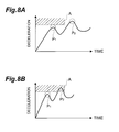
- Fig. 8A and Fig. 8B show an example of graphs showing temporal changes of deceleration (negative acceleration) of a vehicle.
- Fig. 8A shows the vehicle deceleration upon a collision at low speed
- Fig. 8B the vehicle deceleration upon a collision at high speed.
- An activation determination method for the occupant protection apparatus is, for example, a method of setting a determination area A in the graphs shown in Figs. 8A and 8B and activating the occupant protection apparatus when the deceleration reaches the determination area A.
- the present invention has been accomplished in order to solve the above problem and an object of the invention is to provide a vehicle front structure that makes it feasible to make a decision on activation of occupant protection apparatus well, and a method of production of the vehicle front structure. Another object of the present invention is to provide an activation controller for occupant protection apparatus capable of accurately determining whether activation of the occupant protection apparatus is necessary, by utilizing the vehicle front structure.
- a vehicle front structure is characterized by comprising a pair of side members longitudinally located on right and left sides of a vehicle; and a pair of sub side members juxtaposed to the respective side members and adapted to receive a impact load in the event of a frontal collision after the side members receive the impact load.
- the side members first receive the impact load and then the sub side members juxtaposed to the side members also receive the impact load after a certain interval, in collaboration with the side members. Therefore, the vehicle deceleration increases in two stages. Since the vehicle front structure comprises such sub side members, the magnitude of the deceleration in the second stage upon collision can be made greater than that in the first stage, whereby it becomes feasible to make a decision on the activation of the occupant protection apparatus well.
- the sub side members are located below the side members.
- the sub side members can be located without largely affecting the contour of the vehicle.
- each sub side member is supported by a support member extending downward from the each side member.
- a portion going into contact with an obstacle upon a collision of the pair of sub side members is located ahead of the support member.
- front ends of the pair of side members are located ahead of front ends of the pair of sub side members.
- the structure in which the sub side members receive the impact load after the side members receive the impact load it is feasible to suitably realize the structure in which the sub side members receive the impact load after the side members receive the impact load.
- the front ends of the pair of side members are located a predetermined distance c ahead of the front ends of the pair of sub side members.
- This predetermined distance c is set based on a long-side length d and a short-side length e in a rectangular section of the side members and a long-side length f and a short-side length g in a rectangular section of the sub side members.
- a bumper reinforcement with a longitudinal width h is attached to the front ends of the pair of side members and a cross member with a longitudinal width i is attached to the front ends of the pair of sub side members, and the predetermined distance c is represented by Eq (i) below:
- a contraction distance with a maximum (local maximum) impact load on each of the side members and the sub side members is correlated with the long-side length and the short-side length in the rectangular section of each of the side members and the sub side members.
- the impact load on the sub side members has a first maximum substantially at the same time as a second maximum of the impact load on the side members, and it is thus easy to set the magnitude of the vehicle deceleration in the second stage upon collision greater than that in the first stage. This makes it feasible to make a decision on the activation of the occupant protection apparatus better.
- a strength F 0 of the side members and a strength F + of the sub side members satisfy the following relational expression (ii), using an error range ⁇ a% of deceleration detecting means for detecting the deceleration of the vehicle and a distribution range ⁇ b% of decelerations among different vehicle types against an identical impact load:
- the magnitude of the deceleration in the second stage of the vehicle can be made greater than that in the first stage, whereby it is feasible to make a decision on the activation of the occupant protection apparatus better.
- An activation controller for occupant protection apparatus is set in a vehicle with the vehicle front structure described above, and the activation controller comprises: deceleration detecting means for detecting a deceleration of the vehicle; and activation determining means for determining activation of the vehicle protection apparatus, based on the deceleration of the vehicle detected by the deceleration detecting means.
- the activation determining means is able to accurately determine the timing of activation of the occupant protection apparatus, based on the magnitude of the deceleration of the vehicle in the second stage detected by the deceleration detecting means.
- a method of producing a front structure of a vehicle according to the present invention is a method of production of a vehicle front structure in a vehicle comprising a pair of side members longitudinally located on right and left sides of the vehicle and a pair of sub side members juxtaposed to the respective side members, the method comprising a step of determining a location of front ends of the sub side members relative to front ends of the side members, based on a change of vehicle deceleration due to deformation of the side members and a change of vehicle deceleration due to deformation of the sub side members in the event of a frontal collision of the vehicle.
- the location of the front ends of the sub side members relative to a location of the front ends of the side members is determined so that a timing of a second maximum of the vehicle deceleration due to the deformation of the side members overlaps with a timing of a first maximum of the vehicle deceleration due to the deformation of the sub side members.
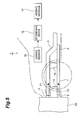
- Fig. 1 is a perspective view showing an embodiment of the vehicle front structure according to the present invention.
- Fig. 2 is a side view from the left side of the vehicle front structure shown in Fig. 1.
- Fig. 3A is a sectional view along line III-III in Fig. 2.
- Fig. 3B is a sectional view along line IV-IV in Fig. 2.
- Fig. 4 is a side view showing a state in which a vehicle is running into an obstacle and in which an impact load is being exerted on the left side member.
- Fig. 5 is a side view showing a state in which a vehicle is running into an obstacle and in which an impact load is being exerted on the left side member and on the left sub side member.
- Fig. 1 is a perspective view showing an embodiment of the vehicle front structure according to the present invention.
- Fig. 2 is a side view from the left side of the vehicle front structure shown in Fig. 1.
- Fig. 3A is a sectional view along line III-
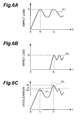
- FIG. 6A is a graph showing an example of time change of the impact load exerted on the left side member upon the collision of the vehicle with the obstacle.
- Fig. 6B is a graph showing an example of time change of the impact load exerted on the left sub side member upon the collision of the vehicle with the obstacle.
- Fig. 6C is a graph showing a time change of vehicle deceleration resulting from application of the impact load to the left side member and application of the impact load to the left sub side member.
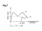
- Fig. 7 is a graph showing the magnitudes of impact loads at a contraction distance in a case where the left side member and the left sub side member receive the respective impact loads to contract.
- Fig. 8A is an example of a graph showing a time change of vehicle deceleration upon a collision at low speed.
- Fig. 8B is an example of a graph showing a time change of vehicle deceleration upon a collision at high speed.
- Fig. 9 is an illustration showing a comparative example of the vehicle front
- Fig. 1 is a perspective view showing an embodiment of the vehicle front structure according to the present invention.
- Fig. 2 is a side view from the left side of the vehicle front structure shown in Fig. 1.
- vehicle 1 is provided with a left side member 3 and a right side member 2.
- the left side member 3 is located in the longitudinal direction on the front left side of vehicle 1.
- the right side member 2 is located in the longitudinal direction on the front right side of vehicle 1.
- the vehicle 1 is also provided with a bumper R/F 4.
- the bumper R/F 4 is disposed in the lateral direction of the vehicle 1.
- the bumper R/F 4 is fixed near each end thereof to the front ends of the right side member 2 and the left side member 3.
- the vehicle 1 has a sub frame 5.
- the sub frame 5 is located below the right side member 2 and the left side member 3, the left front end of the sub frame 5 is fixed to the left side member 3 by coupling member 10, and the right front end of the sub frame 5 is fixed to the right side member 2 by coupling member 9.
- the left rear end of the sub frame 5 is directly fixed to the left side member 3, and the right rear end of the sub frame 5 directly to the right side member 2.
- An engine and other components of vehicle 1 are mounted on the sub frame 5.
- the vehicle 1 is provided with a left sub side member 7 and a right sub side member 6.
- the left sub side member 7 is juxtaposed to the left side member 3.
- the left sub side member 7 extends nearly in parallel with the left side member 3 from the left front end of sub frame 5 toward the front of the vehicle 1, and is supported by a columnar pillar (support member) 12 extending downward from the left side member 3.
- the front end of the left sub side member 7, which is a portion going into contact with an obstacle upon a collision with the obstacle, is located a predetermined distance c behind the front end of the left side member 3.
- the front end of the left sub side member 7 is located ahead of the pillar 12. In this configuration, in the event of a frontal collision, only the left side member 3 first receives an impact load and then the left sub side member 7 receives the impact load, in collaboration with the left side member 3.
- the right sub side member 6 is juxtaposed to the right side member 2.
- the right sub side member 6 extends nearly in parallel with the right side member 2 from the right front end of sub frame 5 toward the front of the vehicle 1 and is supported by a columnar pillar (support member) 11 extending downward from the right side member 2.
- a columnar pillar (support member) 11 extending downward from the right side member 2.
- the front end of the right sub side member 6 is located the predetermined distance c behind the front end of the right side member 2.
- the front end of the right sub side member 6 is located ahead of the pillar 11.
- the vehicle 1 has a cross member 8.
- the cross member 8 is disposed in the lateral direction of the vehicle 1.
- the cross member 8 is fixed near each end to the front ends of the right sub side member 6 and the left sub side member 7.
- Fig. 3A is a sectional view of the left side member 3 (a cross section along line III-III in Fig. 2).
- Fig. 3B is a sectional view of the left sub side member 7 (a cross section along line IV-IV in Fig. 2).
- the left side member 3 and the left sub side member 7 are of columnar shape having a rectangular section, the inside of which is hollow.
- the right side member 2 and the right sub side member 6 are also of the same shape as the left side member 3 and the left sub side member 7.
- the vehicle 1 is provided with an airbag sensor 15, a determining device 16, and an airbag module 17.
- the airbag module 17 internally incorporates an airbag, and an inflator for generating a gas to inflate the airbag, and is an occupant protection apparatus for protecting an occupant in the event of collision.
- the airbag sensor 15 is a deceleration detecting means for detecting the deceleration of vehicle 1.
- the airbag sensor 15 detects the deceleration of vehicle 1 during normal drives and sends a signal indicating the magnitude of deceleration to the determining device 16.
- the determining device 16 is an activation determining means for determining actuation of the airbag device, based on the deceleration of vehicle 1 detected by the airbag sensor 15.
- the determining device 16 is an ECU (Electric Control Unit) and is constructed as internally incorporating a CPU, a ROM, a RAM, and so on.
- the ROM stores an actuation determination program and others.
- the airbag sensor 15 and the determining device 16 constitute an activation controller for actuating the airbag device (inflating the airbag).
- the determining device 16 decides to actuate the airbag device when the deceleration of vehicle 1 from the airbag sensor 15 reaches a predetermined magnitude within a given time.
- the determining device 16 actuates the airbag device, for example, by feeding a signal for actuation of the airbag device to the airbag module 17.
- Fig. 4 is a side view showing a state in which the vehicle 1 in the present embodiment is running into an obstacle 20 and in which an impact load is being applied to the left side member 3.
- Fig. 5 is a side view showing a state in which the vehicle 1 is running into the obstacle 20 and in which an impact load is being applied to the left side member 3 and to the left sub side member 7.
- the description below will concern behaviors of the respective members on the left side in the vehicle front structure, but the members on the right side also demonstrate behaviors similar to those on the left side in the event of a full lap collision.
- the left side of the vehicle will be described as an example, as is also the case in the description of the production method of the vehicle front structure and others given later, the same also applies to the right side.
- the bumper R/F 4 first receives an impact load F1 as shown in Fig. 4. At this time, since a buckling strength (buckling load) of the bumper R/F 4 is higher than an axial collapse strength (axial collapse load) of the left side member 3, the impact load F1 is transferred to the left side member 3, whereby the left side member 3 is deformed near the front end to contract. At this time, the left sub side member 7 is not subjected to any impact load yet.
- buckling load buckling load
- axial collapse strength axial collapse load
- the cross member 8 also receives an impact load F2 as shown in Fig. 5. Since a buckling strength (buckling load) of the cross member 8 is higher than an axial collapse strength (axial collapse load) of the left sub side member 7, the impact load F2 is transferred to the left sub side member 7, whereby the left sub side member 7 is deformed near the front end to contract.
- Fig. 6A is a graph showing an example of time change of the impact load F1 applied to the left side member 3 upon the collision of the vehicle 1 with the obstacle 20.
- Fig. 6B is a graph showing an example of time change of the impact load F2 applied to the left sub side member 7 upon the collision of the vehicle 1 with the obstacle 20.
- Fig. 6C is a graph showing a time change of deceleration of the vehicle 1.
- the impact load F1 reaches the value f 1 , the left side member 3 starts being deformed. Thereafter, the impact load F1 repeats increases and decreases.
- the reason why the impact load F2 starts increasing after the lapse of the constant time is that the front end of the left sub side member 7 is located the predetermined distance c behind the front end of the left side member 3.
- the impact load F2 reaches a value f 2 according to the strength of the left sub side member 7, the left sub side member 7 starts being deformed and thereafter the impact load F2 repeats increases and decreases.
- the time when the impact load F2 first reaches the value f 2 according to the strength of the left sub side member 7 coincides with the time (t t 2 ) when the impact load F1 takes the second maximum. Since the time when the left sub side member 7 starts receiving the impact load F2 can be adjusted by the aforementioned predetermined distance c, properly setting the predetermined distance c enables us to achieve such adjustment that the time when the impact load F2 first reaches the value f 2 becomes t 2 as shown in Fig. 6B.
- the deceleration of the vehicle 1 varies as in the graph shown in Fig. 6C.
- the deceleration of vehicle 1 comes to have a first stage P 1 with a first maximum at the time t 1 .
- the first stage P 1 corresponds to a phenomenon in which the impact load F1 applied to the left side member 3 first reaches the value f 1 .
- the deceleration a 1 since at the time t 1 the vehicle 1 receives f 1 as an impact load, the deceleration a 1 according to the value f 1 acts on the vehicle 1.
- the deceleration of vehicle 1 comes to have a second stage P 2 with a second maximum at the time t 2 .
- the second stage P 2 corresponds to a phenomenon in which the impact load F1 applied to the left side member 3 again reaches f 1 and in which the impact load F2 applied to the left sub side member 7 first reaches the value f 2 . Namely, since at the time t 2 the vehicle 1 receives f 1 +f 2 as an impact load, the deceleration a 2 according to this value f 1 +f 2 acts on the vehicle 1.
- the deceleration a 2 of vehicle 1 at the time t 2 takes a value greater than the previously occurring deceleration a 1 by a degree of the impact load value f 2 . Accordingly, the deceleration of vehicle 1 in the second stage P 2 takes a value greater than that in the first stage P 1 .
- a deceleration as a criterion for the determination in the determining device 16 shown in Fig. 2 on whether the airbag device should be actuated is set to a value between a 1 and a 2 (e.g., a value b shown in Fig. 6C), whereby the determining device 16 can detect the second stage P 2 of deceleration.
- the determining device 16 actuates the airbag device when the second stage P 2 of deceleration occurs within a fixed period from a collision.
- Eq (1) an error range of the airbag sensor 15 is ⁇ a%
- a distribution range of deceleration among different vehicle types in an identical collision mode is ⁇ b%
- the strength (impact collapse load) of the left side member 3 is F 0
- the strength (impact collapse load) of the left sub side member 7 is F + .
- the predetermined distance c As described previously, in order to cause the deceleration as shown in Fig. 6C upon the collision of the vehicle 1 with the obstacle 20, it is preferable to properly set the predetermined distance c. For example, the following two methods can be applied as methods of setting this predetermined distance c.
- the first method is a method of setting the predetermined distance c, based on a long-side length d and a short-side length e in the rectangular section of the left side member 3 (cf. Fig. 3A) and based on a long-side length f and a short-side length g in the rectangular section of the left sub side member 7 (cf. Fig. 3B).
- Fig. 7 is a graph showing a relation between contraction distance and impact load in a case where the left side member 3 and the left sub side member 7 contract under their respective impact loads F1 and F2. As shown in Fig. 7, the impact loads F1 and F2 both repeat increases and decreases (i.e., vibrate), after contraction (buckling) of the left side member 3 and the left sub side member 7.
- L 1 in Fig. 7 represents a contraction distance of the left side member 3 at the second maximum of the impact load F1.
- D 1 a buckling wavelength of the left side member 3
- Eq (2) the distance L 1 is expressed by Eq (2) below.
- L 1 5 4 D 1
- L 2 in Fig. 7 represents a contraction distance of the left sub side member 7 at the first maximum of the impact load F2.
- D 2 the distance L 2 is expressed by Eq (3) below.
- L 2 1 4 D 2
- the buckling wavelength is given by an average of the long-side length and the short-side length of the rectangular section.
- Eq (2) and Eq (3) above reduce to Eqs (4) and (5) below, respectively, using the long-side length d and the short-side length e of the left side member 3 (cf. Fig. 3A) and the long-side length f and the short-side length g of the left sub side member 7 (cf. Fig. 3B).
- L 1 5 8 (d+e)
- L 2 1 8 (f+g)
- the long side of the rectangular section refers to the longer out of the width and height of the left side member 3 (left sub side member 7), and the short side to the other.
- h represents the longitudinal thickness of the bumper R/F 4, and i the longitudinal thickness of the cross member 8.
- the predetermined distance c does not have to precisely satisfy Eq (7).
- Eq (8) below using a constant k (0.5 ⁇ k ⁇ 2), it is quite possible to make the magnitude of deceleration of vehicle 1 in the second stage P 2 greater than that in the first stage P 1 .
- the magnitude of deceleration of vehicle 1 in the second stage P 2 can be readily made larger than that in the first stage P 1 .
- the second method is a method of setting the predetermined distance c, based on deceleration changes upon collision of the left side member 3 and the left sub side member 7.
- samples of the left side member 3 and the left sub side member 7 are prepared and signal waveforms indicating deceleration changes upon collision are acquired by experiment.
- the predetermined distance c is set so that the timing of the second maximum of deceleration of the left side member 3 overlaps with the timing of the first maximum of deceleration of the left sub side member 7, thereby determining the relative location of the sub side member 7 to the left side member 3.
- the term "a timing overlaps with another timing” herein is not limited to a case where the two timings precisely coincide with each other, but it also involves a case where the two timings are approximately coincident with each other.
- the vehicle front structure in the present embodiment has the following effects. Namely, in the vehicle front structure of the present embodiment, the side members 2, 3 first receive the impact load and then the sub side members 6, 7 juxtaposed to the side members 2, 3 also receive the impact load after a certain interval, in collaboration with the side members 2, 3. As a result, the deceleration of vehicle 1 increases in two stages of the first stage P 1 and the second stage P 2 in the early period of collision. When the vehicle 1 is equipped with the sub side members 6, 7 in this way, the magnitude of deceleration in the second stage P 2 upon collision becomes greater than that in the first stage P 1 , whereby it becomes feasible to make a decision on actuation of the airbag device well.
- a vehicle front structure shown in Fig. 9 is a conceivable comparative example of the vehicle front structure to make the magnitude of deceleration in the second stage P 2 greater than that in the first stage P 1 .
- Fig. 9 shows only the left side of the vehicle, but a similar structure is also constructed on the right side of the vehicle.
- a sub frame 37 is provided via coupling member 40 and pillar 42 below the side member 33.
- a bumper R/F 34 is attached to the distal end of the side member 33, and the bumper R/F 34 first receives an impact from the front of the vehicle.
- the side member 33 has a deformable zone 33a with relatively low rigidity near the front end thereof, and in the event of a collision of the vehicle with an obstacle, the deformable zone 33a is first deformed. Then the first stage P 1 of deceleration appears during deformation of the deformable zone 33a and then the second stage P 2 demonstrating the deceleration greater than in the first stage P 1 appears after an end of the deformation of the deformable zone 33a.
- the side member 33 including the deformable zone 33a in order to keep the crush stroke short and to avoid the restrictions on the outside dimensions of the vehicle, it is also possible to increase the total strength of the side member 33 including the deformable zone 33a.
- the increase in the strength of the side member 33 requires a further increase of strength of the compartment zone, so as to largely increase the weight of the vehicle, which is not preferred.
- the vehicle front structure in the present embodiment does not need to secure the long crush stroke and does not increase the range that has to be repaired. Since it is unnecessary to increase the length of the side members 2, 3, there is little influence on the outside dimensions of the vehicle. Since it can absorb an equivalent or greater impact energy without need for increase in the strength of side members 2, 3, there is no need for reinforcement of the compartment zone, which is needed for increase in the strength of side members, and thus an increase in the weight of the vehicle can be minimized.
- the side members 2, 3 and the sub side members 6, 7 receive the impact load, the impact load can be higher than in the case where the impact load is received by the side members 2, 3 only. Accordingly, the deceleration in the initial stage of collision becomes higher on one hand, and the deceleration in the latter half of collision is reduced on the other hand, which improves the occupant restraining performance.
- the sub side members 6, 7 are provided below the side members 2, 3. This permits the sub side members 6, 7 to be placed without largely affecting the contour of the vehicle 1.
- the front ends of the side members 2, 3 are located ahead of the sub side members 6, 7. This makes it feasible to suitably realize the configuration in which, in the event of the collision of the vehicle 1 with obstacle 20, the sub side members 6, 7 receive the impact load after the side members 2, 3 receive the impact load.
- the front ends of the side members 2, 3 are located the predetermined distance c ahead of the front ends of the sub side members 6, 7.
- This predetermined distance c is set based on the long-side length d and the short-side length e in the rectangular section of the side members 2, 3 and the long-side length f and the short-side length g in the rectangular section of the sub side members 6, 7 as indicated by Eq (7) and Eq (8).
- the contraction distance where the impact load F1 becomes maximum in contraction of the side members 2, 3 due to the collision of vehicle 1 is correlated with the long-side length d and the short-side length e in the rectangular section of side members 2, 3.
- the same also applies to the contraction distance where the impact load F2 becomes maximum in contraction of the sub side members 6, 7. Therefore, when the predetermined distance c is set as described above, the impact load F2 on the sub side members 6, 7 takes the first maximum almost at the same time as the second maximum of the impact load F1 on the side members 2, 3, and thus the magnitude of deceleration in the second stage P 2 upon collision can be readily made larger than that in the first stage P 1 . This makes it feasible to make a decision on the actuation of the airbag device better.
- the activation controller for occupant protection apparatus in the present embodiment is provided in the vehicle equipped with the above-stated vehicle front structure and comprises the airbag sensor 15 for detecting the deceleration of vehicle 1, and the determining device 16 for determining the actuation of the airbag device (airbag module 17), based on the deceleration of vehicle 1 detected by the airbag sensor 15.
- the determining device 16 is able to accurately determine the timing of actuation of the airbag device, based on the magnitude of deceleration of vehicle 1 in the second stage P 2 detected by the airbag sensor 15.
- the location of the sub side members 6, 7 relative to the side members 2, 3 is determined in consideration of the deceleration changes of the side members 2, 3 and the sub side members 6, 7 upon collision so that the timing of the second maximum of deceleration of the side members 2, 3 overlaps with the timing of the first maximum of deceleration of the sub side members 6, 7. Accordingly, it is easy to realize the vehicle front structure in which the magnitude of deceleration in the second stage P 2 upon collision of vehicle 1 is greater than that in the first stage P 1 .
- the vehicle front structure of the present invention it is feasible to make a decision on the activation of occupant protection apparatus well.
- the production method of the vehicle front structure of the present invention it is feasible to construct the vehicle front structure capable of making a decision on the activation of occupant protection apparatus well.
- the activation controller for occupant protection apparatus of the present invention a decision on activation can be accurately made, so that the activation of the occupant protection apparatus can be accurately controlled.
Applications Claiming Priority (2)
| Application Number | Priority Date | Filing Date | Title |
|---|---|---|---|
| JP2003133619 | 2003-05-12 | ||
| JP2003133619A JP4403719B2 (ja) | 2003-05-12 | 2003-05-12 | 車両、及び乗員保護装置の起動制御装置 |
Publications (3)
| Publication Number | Publication Date |
|---|---|
| EP1477392A2 true EP1477392A2 (de) | 2004-11-17 |
| EP1477392A3 EP1477392A3 (de) | 2004-12-01 |
| EP1477392B1 EP1477392B1 (de) | 2011-06-29 |
Family
ID=33028326
Family Applications (1)
| Application Number | Title | Priority Date | Filing Date |
|---|---|---|---|
| EP04011212A Expired - Fee Related EP1477392B1 (de) | 2003-05-12 | 2004-05-11 | Kfz-Karosserievorderbau, Steuerung für Insassensicherheitsvorrichtung und Herstellungsverfahren vom Kfz-Vorderbau |
Country Status (3)
| Country | Link |
|---|---|
| US (2) | US7025410B2 (de) |
| EP (1) | EP1477392B1 (de) |
| JP (1) | JP4403719B2 (de) |
Cited By (2)
| Publication number | Priority date | Publication date | Assignee | Title |
|---|---|---|---|---|
| EP1580097A3 (de) * | 2004-03-25 | 2006-06-07 | Mazda Motor Corporation | Fahrzeugvorderstruktur |
| WO2006111310A1 (de) * | 2005-04-22 | 2006-10-26 | Daimlerchrysler Ag | Rahmenkonstruktion zur aufnahme eines schwenkbar gelagerten fahrerhauses eines lastkraftwagens |
Families Citing this family (16)
| Publication number | Priority date | Publication date | Assignee | Title |
|---|---|---|---|---|
| JP4144350B2 (ja) * | 2002-12-26 | 2008-09-03 | トヨタ自動車株式会社 | 車両のフロントボデー構造 |
| DE102004029745B4 (de) * | 2004-06-19 | 2016-10-20 | Volkswagen Ag | Pralldämpfungsvorrichtung für ein Fahrzeug |
| JP4506577B2 (ja) * | 2004-09-21 | 2010-07-21 | トヨタ自動車株式会社 | 車両前部構造 |
| DE102004050435B4 (de) * | 2004-10-16 | 2020-01-16 | Audi Ag | Stoßfängersystem für Kraftfahrzeug |
| DE102005018828B3 (de) * | 2005-04-22 | 2006-08-03 | Daimlerchrysler Ag | Vordere Rahmenkonstruktion eines Lastkraftwagens mit Kollisionsschutz |
| JP2007137336A (ja) * | 2005-11-21 | 2007-06-07 | Denso Corp | 衝突検出装置及び保護装置 |
| JP4872541B2 (ja) * | 2006-08-31 | 2012-02-08 | マツダ株式会社 | 自動車のバンパ構造 |
| JP5057222B2 (ja) * | 2007-09-05 | 2012-10-24 | スズキ株式会社 | 車体前部構造 |
| CN101980891B (zh) | 2008-03-26 | 2013-01-16 | 丰田自动车株式会社 | 碰撞检测结构、碰撞检测系统和方法以及乘员保护系统和方法 |
| JP4957610B2 (ja) * | 2008-03-26 | 2012-06-20 | トヨタ自動車株式会社 | 乗員保護システム |
| JP4640431B2 (ja) * | 2008-03-26 | 2011-03-02 | トヨタ自動車株式会社 | 衝突検知構造及び乗員保護システム |
| JP5446592B2 (ja) * | 2009-08-24 | 2014-03-19 | アイシン精機株式会社 | 車両衝撃判定装置、車両衝撃判定方法および車両衝撃報知装置 |
| US8152224B2 (en) * | 2010-04-21 | 2012-04-10 | Ford Global Technologies | Vehicle front-end upper load path assembly |
| JP2012045995A (ja) * | 2010-08-25 | 2012-03-08 | Nissan Motor Co Ltd | 車体構造 |
| ITBO20120271A1 (it) * | 2012-05-16 | 2013-11-17 | Ferrari Spa | Puntone collassabile a deformazione controllata per il telaio di un veicolo stradale |
| US10328879B2 (en) * | 2017-06-30 | 2019-06-25 | Honda Motor Co., Ltd. | Bumper bean design for crash signal separation |
Citations (1)
| Publication number | Priority date | Publication date | Assignee | Title |
|---|---|---|---|---|
| US20030075951A1 (en) | 2001-09-21 | 2003-04-24 | Mazda Motor Corporation | Body frame structure for a vehicle and method for manufacturing thereof |
Family Cites Families (10)
| Publication number | Priority date | Publication date | Assignee | Title |
|---|---|---|---|---|
| US4842301A (en) * | 1988-09-02 | 1989-06-27 | General Motors Corporation | Acoustic emission automotive crash sensor |
| JP2983704B2 (ja) * | 1990-08-09 | 1999-11-29 | マツダ株式会社 | 車両の衝突センサ取り付け構造 |
| FR2800695B1 (fr) * | 1999-11-08 | 2001-12-07 | Renault | Vehicule, notamment de tourisme, a structure d'encaissement de choc anti-chevauchement |
| JP3806286B2 (ja) | 2000-06-15 | 2006-08-09 | 三菱自動車工業株式会社 | 車体構造 |
| JP3487279B2 (ja) * | 2000-10-02 | 2004-01-13 | トヨタ自動車株式会社 | 乗員保護装置の起動制御装置 |
| JP3591499B2 (ja) * | 2001-08-31 | 2004-11-17 | 日産自動車株式会社 | 車体前部構造 |
| JP3687596B2 (ja) | 2001-11-29 | 2005-08-24 | 日産自動車株式会社 | 車両前部構造 |
| JP3632666B2 (ja) | 2002-02-01 | 2005-03-23 | 日産自動車株式会社 | 車体前部構造 |
| JP4306229B2 (ja) * | 2002-04-03 | 2009-07-29 | タカタ株式会社 | 衝突検出装置及び安全装置 |
| JP3693053B2 (ja) * | 2003-01-07 | 2005-09-07 | 日産自動車株式会社 | 車両衝突状態検出装置 |
-
2003
- 2003-05-12 JP JP2003133619A patent/JP4403719B2/ja not_active Expired - Fee Related
-
2004
- 2004-05-05 US US10/838,260 patent/US7025410B2/en not_active Expired - Fee Related
- 2004-05-11 EP EP04011212A patent/EP1477392B1/de not_active Expired - Fee Related
-
2005
- 2005-12-05 US US11/293,266 patent/US7201249B2/en not_active Expired - Fee Related
Patent Citations (1)
| Publication number | Priority date | Publication date | Assignee | Title |
|---|---|---|---|---|
| US20030075951A1 (en) | 2001-09-21 | 2003-04-24 | Mazda Motor Corporation | Body frame structure for a vehicle and method for manufacturing thereof |
Cited By (3)
| Publication number | Priority date | Publication date | Assignee | Title |
|---|---|---|---|---|
| EP1580097A3 (de) * | 2004-03-25 | 2006-06-07 | Mazda Motor Corporation | Fahrzeugvorderstruktur |
| US7213873B2 (en) | 2004-03-25 | 2007-05-08 | Mazda Motor Corporation | Vehicle front-part structure |
| WO2006111310A1 (de) * | 2005-04-22 | 2006-10-26 | Daimlerchrysler Ag | Rahmenkonstruktion zur aufnahme eines schwenkbar gelagerten fahrerhauses eines lastkraftwagens |
Also Published As
| Publication number | Publication date |
|---|---|
| EP1477392B1 (de) | 2011-06-29 |
| US20040239149A1 (en) | 2004-12-02 |
| US20060082124A1 (en) | 2006-04-20 |
| US7025410B2 (en) | 2006-04-11 |
| US7201249B2 (en) | 2007-04-10 |
| EP1477392A3 (de) | 2004-12-01 |
| JP4403719B2 (ja) | 2010-01-27 |
| JP2004331018A (ja) | 2004-11-25 |
Similar Documents
| Publication | Publication Date | Title |
|---|---|---|
| US7201249B2 (en) | Vehicle front structure, activation controller for occupant protection apparatus, and method of production of vehicle front structure | |
| EP1350682B1 (de) | Vorrichtung zur Kollisionserkennung und passive Sicherheitseinrichtung | |
| US6361092B1 (en) | Automotive frame bumper interface for discriminated deceleration response | |
| US6463372B1 (en) | Vehicle collision damage reduction system | |
| JP3141534B2 (ja) | エアバック制御装置 | |
| JP3459776B2 (ja) | 乗員保護装置 | |
| US9409601B2 (en) | Motor vehicle having an axle support | |
| US7448642B2 (en) | Impact absorbing airbag inflator | |
| US7321817B2 (en) | Automobile frontal collision location detection for coordinated activation of safety systems | |
| US20120296526A1 (en) | Control unit for setting a device for the adaptive reduction of crash energy for a vehicle, device for the adaptive reduction of crash energy for a vehicle and method for setting a device for the adaptive reduction of crash energy for a vehicle | |
| US9725059B2 (en) | Vehicle collision determination apparatus | |
| JP2001206176A (ja) | 車輌の乗員保護装置 | |
| CN111660994B (zh) | 车辆用气囊装置、车辆用气囊装置的控制方法及存储介质 | |
| US7237828B2 (en) | Underbody crash device for a vehicle | |
| JP3946141B2 (ja) | 乗物構造部分を弱化させる装置 | |
| US7165787B1 (en) | Safety device for motor-vehicle steering column and seat belts | |
| US7275775B2 (en) | Crash acceleration pulse control block for vehicle | |
| US7441826B2 (en) | Energy transfer beam for automotive side door | |
| GB2449539A (en) | A system and method for clearing the crush space in a vehicle | |
| EP2511141B1 (de) | Aufprallenergieabsobierende Vorrichtung und Verfahren zur Steuerung der bei einem Aufprall auf ein Fahrzeug übertragenen Energie | |
| JP2004161109A (ja) | 車両のエネルギー吸収構造体 | |
| JP2003511309A (ja) | 複数の衝突モードを持つ車両 | |
| US20060090946A1 (en) | Vehicle side collision occupant restraint system | |
| JP2015077826A (ja) | 車両衝突判定装置 | |
| US20100140967A1 (en) | Motor Vehicle |
Legal Events
| Date | Code | Title | Description |
|---|---|---|---|
| PUAI | Public reference made under article 153(3) epc to a published international application that has entered the european phase |
Free format text: ORIGINAL CODE: 0009012 |
|
| PUAL | Search report despatched |
Free format text: ORIGINAL CODE: 0009013 |
|
| 17P | Request for examination filed |
Effective date: 20040609 |
|
| AK | Designated contracting states |
Kind code of ref document: A2 Designated state(s): AT BE BG CH CY CZ DE DK EE ES FI FR GB GR HU IE IT LI LU MC NL PL PT RO SE SI SK TR |
|
| AX | Request for extension of the european patent |
Extension state: AL HR LT LV MK |
|
| AK | Designated contracting states |
Kind code of ref document: A3 Designated state(s): AT BE BG CH CY CZ DE DK EE ES FI FR GB GR HU IE IT LI LU MC NL PL PT RO SE SI SK TR |
|
| AX | Request for extension of the european patent |
Extension state: AL HR LT LV MK |
|
| AKX | Designation fees paid |
Designated state(s): DE FR GB |
|
| 17Q | First examination report despatched |
Effective date: 20061218 |
|
| GRAP | Despatch of communication of intention to grant a patent |
Free format text: ORIGINAL CODE: EPIDOSNIGR1 |
|
| GRAS | Grant fee paid |
Free format text: ORIGINAL CODE: EPIDOSNIGR3 |
|
| GRAA | (expected) grant |
Free format text: ORIGINAL CODE: 0009210 |
|
| AK | Designated contracting states |
Kind code of ref document: B1 Designated state(s): DE FR GB |
|
| REG | Reference to a national code |
Ref country code: GB Ref legal event code: FG4D |
|
| REG | Reference to a national code |
Ref country code: DE Ref legal event code: R096 Ref document number: 602004033246 Country of ref document: DE Effective date: 20110818 |
|
| PLBE | No opposition filed within time limit |
Free format text: ORIGINAL CODE: 0009261 |
|
| STAA | Information on the status of an ep patent application or granted ep patent |
Free format text: STATUS: NO OPPOSITION FILED WITHIN TIME LIMIT |
|
| 26N | No opposition filed |
Effective date: 20120330 |
|
| REG | Reference to a national code |
Ref country code: DE Ref legal event code: R097 Ref document number: 602004033246 Country of ref document: DE Effective date: 20120330 |
|
| REG | Reference to a national code |
Ref country code: GB Ref legal event code: 746 Effective date: 20130215 |
|
| REG | Reference to a national code |
Ref country code: DE Ref legal event code: R084 Ref document number: 602004033246 Country of ref document: DE Effective date: 20130312 |
|
| REG | Reference to a national code |
Ref country code: FR Ref legal event code: PLFP Year of fee payment: 12 |
|
| PGFP | Annual fee paid to national office [announced via postgrant information from national office to epo] |
Ref country code: DE Payment date: 20150506 Year of fee payment: 12 Ref country code: GB Payment date: 20150506 Year of fee payment: 12 |
|
| PGFP | Annual fee paid to national office [announced via postgrant information from national office to epo] |
Ref country code: FR Payment date: 20150508 Year of fee payment: 12 |
|
| REG | Reference to a national code |
Ref country code: DE Ref legal event code: R119 Ref document number: 602004033246 Country of ref document: DE |
|
| GBPC | Gb: european patent ceased through non-payment of renewal fee |
Effective date: 20160511 |
|
| REG | Reference to a national code |
Ref country code: FR Ref legal event code: ST Effective date: 20170131 |
|
| PG25 | Lapsed in a contracting state [announced via postgrant information from national office to epo] |
Ref country code: DE Free format text: LAPSE BECAUSE OF NON-PAYMENT OF DUE FEES Effective date: 20161201 Ref country code: FR Free format text: LAPSE BECAUSE OF NON-PAYMENT OF DUE FEES Effective date: 20160531 |
|
| PG25 | Lapsed in a contracting state [announced via postgrant information from national office to epo] |
Ref country code: GB Free format text: LAPSE BECAUSE OF NON-PAYMENT OF DUE FEES Effective date: 20160511 |