EP1475758B1 - Vorrichtung zum Anhalten eines Motors - Google Patents
Vorrichtung zum Anhalten eines Motors Download PDFInfo
- Publication number
- EP1475758B1 EP1475758B1 EP04004712A EP04004712A EP1475758B1 EP 1475758 B1 EP1475758 B1 EP 1475758B1 EP 04004712 A EP04004712 A EP 04004712A EP 04004712 A EP04004712 A EP 04004712A EP 1475758 B1 EP1475758 B1 EP 1475758B1
- Authority
- EP
- European Patent Office
- Prior art keywords
- reel
- motor
- stop control
- vibration
- stepping motor
- Prior art date
- Legal status (The legal status is an assumption and is not a legal conclusion. Google has not performed a legal analysis and makes no representation as to the accuracy of the status listed.)
- Expired - Lifetime
Links
- 230000005284 excitation Effects 0.000 claims abstract description 92
- 238000013016 damping Methods 0.000 claims description 22
- 230000000694 effects Effects 0.000 claims description 21
- 230000005540 biological transmission Effects 0.000 claims description 13
- 238000000034 method Methods 0.000 description 284
- 238000012986 modification Methods 0.000 description 16
- 230000004048 modification Effects 0.000 description 16
- 238000004519 manufacturing process Methods 0.000 description 12
- 230000014509 gene expression Effects 0.000 description 6
- 238000001514 detection method Methods 0.000 description 5
- 238000012545 processing Methods 0.000 description 3
- 239000004952 Polyamide Substances 0.000 description 2
- 230000003139 buffering effect Effects 0.000 description 2
- 238000004364 calculation method Methods 0.000 description 2
- 230000005489 elastic deformation Effects 0.000 description 2
- 238000003780 insertion Methods 0.000 description 2
- 230000037431 insertion Effects 0.000 description 2
- 239000000463 material Substances 0.000 description 2
- 229920002647 polyamide Polymers 0.000 description 2
- JOYRKODLDBILNP-UHFFFAOYSA-N Ethyl urethane Chemical compound CCOC(N)=O JOYRKODLDBILNP-UHFFFAOYSA-N 0.000 description 1
- 230000003466 anti-cipated effect Effects 0.000 description 1
- 230000001419 dependent effect Effects 0.000 description 1
- 238000010586 diagram Methods 0.000 description 1
- 238000005516 engineering process Methods 0.000 description 1
- 230000005281 excited state Effects 0.000 description 1
- 230000002093 peripheral effect Effects 0.000 description 1
- 238000007747 plating Methods 0.000 description 1
- 238000005070 sampling Methods 0.000 description 1
- 238000012216 screening Methods 0.000 description 1
Images


Classifications
-
- G—PHYSICS
- G07—CHECKING-DEVICES
- G07F—COIN-FREED OR LIKE APPARATUS
- G07F17/00—Coin-freed apparatus for hiring articles; Coin-freed facilities or services
- G07F17/32—Coin-freed apparatus for hiring articles; Coin-freed facilities or services for games, toys, sports, or amusements
- G07F17/3202—Hardware aspects of a gaming system, e.g. components, construction, architecture thereof
- G07F17/3204—Player-machine interfaces
- G07F17/3211—Display means
- G07F17/3213—Details of moving display elements, e.g. spinning reels, tumbling members
-
- G—PHYSICS
- G07—CHECKING-DEVICES
- G07F—COIN-FREED OR LIKE APPARATUS
- G07F17/00—Coin-freed apparatus for hiring articles; Coin-freed facilities or services
- G07F17/32—Coin-freed apparatus for hiring articles; Coin-freed facilities or services for games, toys, sports, or amusements
- G07F17/3202—Hardware aspects of a gaming system, e.g. components, construction, architecture thereof
-
- H—ELECTRICITY
- H02—GENERATION; CONVERSION OR DISTRIBUTION OF ELECTRIC POWER
- H02P—CONTROL OR REGULATION OF ELECTRIC MOTORS, ELECTRIC GENERATORS OR DYNAMO-ELECTRIC CONVERTERS; CONTROLLING TRANSFORMERS, REACTORS OR CHOKE COILS
- H02P8/00—Arrangements for controlling dynamo-electric motors rotating step by step
- H02P8/24—Arrangements for stopping
- H02P8/30—Holding position when stopped
Definitions
- This invention relates to a motor stop control device for a rotating reel type gaming machine which includes a motor having two pairs of excitation phases as a driving source of reels having a plurality of symbols drawn thereon and in which the motor is stopped in accordance with an operational instruction from outside.
- reels are directly connected to a rotating shaft of a stepping motor (direct drive method). Since the direct drive method involves a structure in which rotational torque of the stepping motor is directly transmitted to the rotating shafts of the reels, the structure around the stepping motor is simplified.
- the document GB-A-1471866 discloses the features in the preamble of claim 1.
- the direct drive method involves no mechanical decelerating means
- the stepping motor has been required to generate rotational torque in accordance with the inertia of the reels, and an expensive stepping motor capable of generating high torque (e.g., a hybrid type) has been therefore used. This has resulted in a problem in that a significant reduction cannot be achieved in the manufacturing cost of a reel unit including the stepping motor.
- reels are controlled by performing stop control of the stepping motor through full-phase excitation, and it is common to employ a method utilizing detent torque of the stepping motor.
- the detent torque can vary from reel to reel, and inertia also varies from reel to reel. Therefore, the stopping positions of the symbols have been unstable, and it has been impossible to stop the symbols displayed on the surface of the reels with high accuracy.
- the invention has been made taking the above points into consideration, and it is an object of the invention to provide a motor stop control device which makes it possible to reduce the cost of a stepping motor, to manufacture a reel unit with a smaller number of steps, and to stop the reel at accurate positions without reducing the smoothness of the braking of the stepping motor.
- this invention provides a motor stop control device for a rotating reel type gaming machine which includes a motor having two pairs of excitation phases as a driving source of a reel having a plurality of symbols drawn thereon and in which the motor is stopped in accordance with an operational instruction from the outside, the motor stop control device comprising a deceleration transmission mechanism for transmitting the rotation of the motor to a rotating shaft for rotating the reel at a predetermined reduction ratio; motor stop control means for performing stop control of the motor through two-phase excitation when a motor stop command is generated according to an operational instruction from the outside; and a vibration-suppressing member for damping vibration of the reel occurring when the rotation of the reel is stopped by the stop control of the motor stop control means, characterized in that: the motor is a stepping motor; the deceleration transmission mechanism has an output-side gear provided on a driving side of the stepping motor and an input-side gear disposed at the reel such that the input-side gear is in contact with the output-side gear and coaxial with the rotating shaft
- the motor stop control means since the rotation of the motor is transmitted to the rotating shafts for rotating the reel at a predetermined reduction ratio, a designer can adopt a low cost motor having small rotational torque (e.g., a PM type). Further, since the motor stop control means performs motor stop control through two-phase excitation after performing control for reducing the rotating speed of the motor, the motor stop control means can stop the reel at accurate positions.
- the motor stop control means performs the control for reducing the rotating speed of the motor
- the motor stop control means can more preferably stop the reel at accurate positions without reducing the smoothness of the braking of the motor than reducing the motor rotating speed abruptly. Since the stoppage of the reel is thus independent upon braking utilizing detent torque, no balance adjustment as described above is required at the time of manufacture, and operators can manufacture a reel unit with a small number of steps.
- the motor stop control means may be adapted to perform the stop control through two-phase excitation by transmitting pulses in a number corresponding to a predetermined time interval.
- the vibration-suppressing member provides a braking function when the reel are rotating and damps the vibration of the reel occurring when the motor is braked, the vibration-suppressing member allows the reel to be stopped at accurate positions without reducing the smoothness of the braking of the motor. As a result, no balance adjustment as described above is required at the time of manufacture, and operators can manufacture a reel unit with a small number of steps.
- the reduction ratio is preferably determined by the ratio between the number of steps of one rotation of the motor and the least common multiple calculated from the number of symbols displayed on the reel and the number of steps of one rotation of a stepping motor.
- the motor can stop a symbol at an appropriate position because of the reduction ratio.
- the deceleration transmission mechanism may comprise an output-side gear and an input-side gear constituted by spur gears, and either of the output-side gear and the input-side gear may be a scissors gear.
- the material of the spur gears may be a soft member such as polyamide.
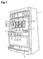
- FIG. 1 shows an appearance of a rotating reel type gaming machine 1 according to this embodiment.
- three panel display windows 5L, 5C and 5R are formed on a front surface of a cabinet that forms the outline of the rotating reel type gaming machine 1 as a whole. Reels 3L, 3C and 3R that form a reel unit are visually observed through those panel display windows 5L, 5C and 5R.
- Five pay lines 6 are drawn on the panel display windows 5L, 5C and 5R such that three of them extend horizontally and two diagonally, and the number of pay lines 6 that are enabled is determined by the number of coins inserted into an insertion slot 7.
- Fig. 2 is a perspective view showing a configuration of a reel unit provided inside the respective panel display windows 5L, 5C and 5R.
- the reel unit has three mounting plates 80L, 80C and 80R, three reels 3L, 3C and 3R provided inside the respective mounting plates 80L, 80C and 80R, and three PM-type stepping motors 70L, 70C and 70R for driving the reels 3L, 3C and 3R for rotation independently of each other.
- the following description will focus on the reel 3L (reel 3), the mounting plate 80L (mounting plate 80), and the stepping motor 70L (stepping motor 70) located on the right among the three reels 3L, 3C and 3R, the three mounting plates 80L, 80C and 80R, and the three stepping motors 70L, 70C and 70R, respectively.
- the other respective reels 3C and 3R, respective plating plates 80C and 80R, and respective stepping motors 70C and 70R are identical in configuration.
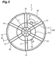
- Fig. 3 is a right side view of the reel 3.
- a position-detecting sensor 10 as a reel position detecting circuit for detecting the rotating position of the reel 3 is provided on the mounting plate 80 (not shown) within a rotating radius rl of the reel 3.
- the reel 3 is pivotally supported at the center thereof such that it can rotate about a reel post 76 perpendicularly extending from a surface of the mounting plate 80.
- the reel 3 comprises six arms 31 radially extending from the center thereof and a cylindrical member 32 that is integrally formed with ends of the respective arms 31 in the extending direction thereof so as to extend between them.
- a detection piece 11 to serve as a reference position is provided on one of the arms 31, in a position that can be detected by a position-detecting sensor 10.
- the detection piece 11 is provided such that it passes through the position-detecting sensor 10 each time the reel 3 makes one rotation.
- the position-detecting sensor 10 is formed to be able to output a detection signal each time it detects the detection piece 11 as the detection piece 11 passes through the same.
- a total of twenty-one symbol marks 33 are printed at constant intervals at a side peripheral edge of the cylindrical member 32.
- a symbol sheet (not shown) is applied.
- the symbol sheet is attached to an outer periphery of the cylindrical member 32 using a method such as boding such that symbols displayed thereon is centered on the symbol marks 33.
- a deceleration transmission mechanism 700 is disposed between a drive shaft of the stepping motor 70 and a rotating shaft of the reel 3.
- the deceleration transmission mechanism 700 transmits rotation of the stepping motor 70 to the rotating shaft that rotates the reel 3 at a predetermined reduction ratio.
- the deceleration transmission mechanism 700 has an output-side gear 71 provided on a driving side of the stepping motor 70 and an input-side gear 72 disposed at the reel 3 such that it is in contact with the output-side gear 71 and coaxial with the support shaft of the reel 3.
- the deceleration transmission mechanism 700 is configured to transmit the speed of rotation of the stepping motor 70 to the reel 3 with a speed reduction by a factor of 7.
- the gear ratio (reduction ratio) between the output-side gear 71 and the input-side gear 72 is determined from the ratio between the number of steps of one rotation of the stepping motor 70 and the least common multiple calculated from the number of symbols displayed on the reel 3 and the number of steps of one rotation of the stepping motor 70.
- the gear ratio between the output-side gear 71 and the input-side gear 72 can be determined as "1:7 ⁇ n (n is an integer)".
- the driving frequency is within a range of proper driving frequencies (about 300 to 500 pps) for the stepping motor 70 of two-phase excitation.
- n 2 or more
- the driving frequency of the stepping motor 70 is 896 pps or more according to the similar calculation and is therefore out of the range of proper driving frequencies.
- n 1 (the rotating speed of 80 rpm, the gear ratio of 1:7, and the number of steps of 48) constitutes an optimum condition. That is, a proper reduction ratio is uniquely determined by a combination of "the least common multiple of the number of steps of one rotation of the stepping motor 70 and the number of symbols" and "the driving frequency of the stepping motor 70".
- Fig. 4 is a perspective view showing the neighborhood of the rotating shaft of the reel 3.
- Fig. 5(a) shows a structure of an axial support portion 720 for axially rotatably supporting the reel 3.
- Fig. 5(b) is a sectional view showing a structure for axially supporting the reel 3 with the axial support portion 720 fixed to the mounting plate 80.
- Fig. 6 is a sectional view showing the entire structure in which the axial support portion 720 axially supports the reel 3.
- the axial support portion 720 has a fastening member 73, collars 74a and 74b, a vibration-suppressing member 75, and a reel post 76.
- the reel post 76 has a rotational axial support portion 76a into which the input-side gear 72 is inserted to be rotatably axially supported thereby, a position fixing portion 76b for inserting a member for fixing the position of the reel 3, a protrusion 76c protruding from the bottom of the reel post 76 toward the mounting plate 80 for inserting and fitting the reel post 76 into a hole 81 in the mounting plate 80, threaded holes 76d for fixing the real post 76 to the mounting plate 80 with screws, and a fastening hole 76e for removal-stopping the input-side gear 72 using the fastening member 73 (which is a screw, for example) with the collars 74a and 74b and the vibration-suppressing member 75 interposed.
- the vibration-suppressing member 75 provides a braking function during the rotation of the reel 3 under stop control effected by a main CPU 40 and damps any vibration of the reel 3 that occurs when the reel 3 stops rotating.
- the vibration-suppressing member 75 may be a spring.
- a spring 75 is used as the vibration-suppressing member 75 of this embodiment. As shown in Fig. 5 (b), after the input-side gear 72 is inserted into the rotational axial support portion 76a, the spring 75 is inserted into the position fixing portion 76b in a state in which it is sandwiched between the collars 74a and 74b.
- the fastening member 73 is inserted into the fastening hole 76e for removal-stopping the collars 74a and 74b and the spring 75 inserted in the position fixing portion 76b. Because of the resilience of the spring 75, the spring 75 removal-stopped by the fastening member 73 urges the input-side gear 72 against the mounting plate 80 through the collar 74b. Thanks to a frictional force generated at this time, the vibration-suppressing member 75 can damp any vibration of the reel 3 occurring when the reel 3 stops rotating.
- the input-side gear has protrusions 72a and 72b that are integral therewith, the protrusions perpendicularly protruding from both sides of the gear in the form of a flat plate and having a cavity into which the rotational axial support portion 76a can be inserted along their perpendicular axes.
- the input-side gear 72 is inserted into the rotational axial support portion 76a with the protrusion 72b directed toward the mounting plate 80.
- the other protrusion 72a is press-fitted into a hole 34 provided at the center of the reel 3. Therefore, when the output-side gear 72 rotates, the reel 3 and the input-side gear rotate integrally with each other about the rotational axial support portion 76a.
- Fig. 7 is a block diagram showing an electrical configuration of the rotating reel type gaming machine 1 including a motor stop control device.
- the motor stop control device has a stepping motor 70 having two pairs of excitation phases as a driving source of reels 3 displaying a plurality of symbols and stops the stepping motor 70 according to an operational instruction from the outside.
- a configuration corresponding to the motor control stop device corresponds to the configuration shown in Fig. 7.
- a microcomputer has a main CPU 40 (motor stop process means) which plays a primary role in control and calculations, a program ROM 40b in which programs and fixed data are stored, a control RAM 40a used for reading and writing data, and a random number generator (not shown) for generating predetermined random numbers.
- main CPU 40 motor stop process means
- program ROM 40b in which programs and fixed data are stored
- control RAM 40a used for reading and writing data
- random number generator (not shown) for generating predetermined random numbers.
- a start lever 9 for detecting an operation of the start lever 9
- a reel stop signal circuit 12 for detecting operations of the stop buttons 4L, 4C and 4R
- BET switches 2a to 2c for betting credited medals through operations on pushbuttons and output portions such as a motor drive circuit 20, a medal payout portion (not shown), and a game effects control performing portion 50.
- the main CPU 40 reads and write data from and in the control RAM 40a according to a program stored in the program ROM 40b to control the operations of the input and output portions in conjunction with each other, and executes a lottery process using a random number generated by the random number generator.
- the game effects control performing portion 50 performs effects according to the lottery process based on a command from the main CPU 40.
- the main CPU 40 internally performs the lottery process after detecting an operation of the start lever 9.
- the main CPU 40 performs the lottery process by sampling a predetermined random number generated by the random number generator and judging whether the sampled random number is within a predetermined range. No detailed description is given on the lottery process because it is publicly known.
- stop control When a stop process is thereafter performed with the stop buttons 4L, 4C and 4R, if the lottery has internally resulted in winning, the main CPU 40 executes stop control after lining up a predetermined symbol which has been won on a pay line. When the lottery has internally resulted in no winning, stop control is executed after performing a process of sliding the timing of the stop operation with the stop buttons 4L, 4C and 4R such that no predetermined winning symbol combination is enabled (this process is to slide a predetermined number of symbols).
- a process is hereinafter referred to as "symbol process" when it includes the process of the main CPU 40 of lining up a predetermined symbol that has been won on a pay line and the process of the sliding a predetermined number of symbols such that no predetermined winning symbol combination is enabled.
- the motor drive circuit 20 drives or stops the stepping motor 70 based on a command from the main CPU 40.
- the motor drive circuit 20 performs a chopper operation to control a current flowing through a drive coil.
- the term "chopper operation" means repeatedly turning a current on and off at a high frequency.
- the motor drive circuit 20 can efficiently drive the rotor of the stepping motor 70 for rotation.
- the stepping motor 70 is a four-phase motor having drive coils in A- to D-phases.
- the phases are counterclockwise arranged in the order of A-, B-, C-, and D-phases.
- the A- and C-phases or the B- and D-phases are paired, and a current flowing in one of two phases is opposite in phase to a current flowing in the other phase.
- the motor drive circuit 20 sequentially drives the drive coils in the respective phases based on a command from the main CPU 40 to drive the rotor in the stepping motor 70 for rotation.
- a phase-shifted pulse is supplied form the main CPU 40 to a bipolar transistor (or a unipolar transistor) provided in each phase of the motor drive circuit 20.
- While driving methods for a stepping motor include one-phase excitation, two-phase excitation, and "one-two phase excitation", this embodiment employs the two-phase excitation method in which drive coils in two phases are simultaneously excited.
- Two-phase (e.g., the C- and D-phase) excitation means that a current flows in two excitation phases such that magnetic fields are generated in the same direction in the two excitation phases among the two pairs of excitation phases. Stop control relying upon the two-phase (e.g., the C- and D-phases) excitation provides a braking force higher than those achievable with full-phase excitation, one-phase excitation, and three-phase excitation.
- a PM type stepping motor having 48 steps per rotation or a rotational angle of 7.5 deg per step is used as the stepping motor 70 of this embodiment.
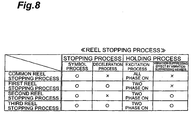
- Fig. 8 shows the contents of a reel stopping process performed by the moment when the reel 3 is finally stopped.
- the reel stopping process includes a "stopping process” representing a process since a press on any of the stop buttons 4 until a holding is started and a “holding process” representing a process until the reel 3 is completely stopped after the end of the "stopping process”.
- the "stopping process” shown in Fig. 8 includes a "symbol process” for performing the process of the main CPU 40 of lining up a predetermined symbol that has been won on a pay line or the process of the main CPU 40 of sliding a predetermined number of symbols such that no predetermined winning symbol combination is enabled, the symbol process being performed after the stop button 4 is pressed until the reel 3 comes close to a target stop position.
- the stopping process also includes a “decelerating process” for performing a control process to decelerate the rotating speed of the stepping motor 70 to stop the same after the end of the "symbol process" until the reel 3 is stopped at the target stop position.
- the “deceleration process” employs two-phase (e.g. the B- and C-phases) excitation.
- the "holding process” includes an excitation process” representing a process of exciting each phase to stop the stepping motor 70 (stop control) and a "vibration-suppressing effect by a vibration-suppressing member 75" representing damping of any vibration of the reel 3 occurring when the stepping motor 70 stops rotating by the use of a vibration-suppressing member 75.
- the reel stopping process including the “stopping process” and the “holding process” includes a “common reel stopping process”, a “first reel stopping process”, a “second reel stopping process”, and a “third reel stopping process”. Those reel stopping processes will be described below in the order listed.
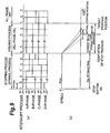
- Fig. 9 shows the contents of the common reel stopping process.
- Fig. 9(a) shows pulses in each phase transmitted from the main CPU 40 to the motor drive circuit 20 during the "stopping process” and the "holding process”.
- Fig. 9(b) shows the rotating speed of the reel 3 relative to time measured when the motor drive circuit 20 drives the stepping motor 70 based on the pulses in each phase received from the main CPU 40.
- the time shown in Fig. 9(b) according to this embodiment corresponds to the time shown in Fig. 9(a).
- the "common reel stopping process” means a reel stopping process which has been conventionally performed.
- the two dotted lines shown in Fig. 9(b) indicate a range within which an actual stopping position can vary.
- An actual stopping position is determined by balance between the detent torque of the stepping motor 70 and the inertia of the reel 3. Therefore, the actual stopping position varies depending on the balance. Since the balance is artificially adjusted, an increase in manufacturing cost occurs.
- the variation of the "actual stopping position" is substantially 0 in the "first through third reel stopping processes" because they employ the "deceleration process", “excitation process” or "vibration-suppressing effect by the vibration-suppressing member 75".
- the “common reel stopping process” means that the “symbol process” is performed after the stop button 4 is pressed and that the “excitation process” is performed on a full-phase excitation basis to stop the reel 3.
- the “common reel stopping process” does not involve the “deceleration process” and the vibration-suppressing effect by the vibration-suppressing member 75" involved in the first through third reel stopping processes.
- the “common reel stopping process” does not involve the deceleration transmission mechanism 700 but involves a driving mechanism provided by the stepping motor 70 according the direct driving method.
- interrupt processes are performed in the "common reel stopping process" at time intervals of, for example, 1.8773 ms.
- the time intervals between the interrupt processes are determined by the driving frequency of the stepping motor 70.
- the number of rotations per second of the reel 3 is 80 rpm/60 sec; the number of steps per rotation of the stepping motor 70 is 200; and one-two phase excitation is used as the excitation method. Then, the number of steps per rotation is 400, and the driving frequency S of the stepping motor 70 is 533 pps from the above relational expression.
- a vibration period T that is 1/S therefore becomes 1.875 ms. Since the vibration period T (1.875 ms) is a value near a minimum clock period (e.g., 1.2 ms) used in the main CPU 40 (vibration period T > clock period), the interrupt processes are performed at the time intervals of 1.875 ms.
- a minimum clock period e.g., 1.2 ms
- the maximum number of interrupts since a press on the stop button 4 until the completion of the stopping process can be obtained from the following relational expression.
- One step corresponds to one interrupt according to the above relational expression for the vibration period T.
- the "stopping process" of by the main CPU 40 is performed within about 190 ms, as shown in Fig. 9.
- the main CPU 40 performs stop control on a full-phase excitation (all phases ON) basis for about 375 ms (200 (interrupts) ⁇ 1.875 ms).
- the stepping motor 70 needs a braking time At which is actually measured at about 100 ms. Since the full-phase excitation is equivalent to non-excited state, only detent torque Td of the stepping motor 70 constitutes load torque at this braking process.
- the detent torque Td is given by J• ⁇ / ⁇ t and where At represents the braking time after the completion of the stopping process until stopping at an anticipated position and where J represents a moment of inertia that is momentum generated at the rotating shaft of the reel 3, and the braking time ⁇ t is given by J• ⁇ /Td. As shown in Fig.
- the braking time ⁇ t in the conventional "common reel stopping process” is longer than a braking time in the "first reel stopping process", the “second reel stopping process” or the “third reel stopping process” according to the invention because the rotating shaft of the stepping motor 70 is directly fitted into the reel 3 in the middle thereof and because the “deceleration process” and the "vibration-suppressing effect by the vibration-suppressing member 75" according to this embodiment are not involved.
- the “first reel stopping process”, the "second reel stopping process”, and “the third reel stopping process” will be described below in the order listed.
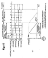
- Fig. 10 shows the contents of the "first reel stopping process”.
- Fig. 10(a) shows pulses in each phase transmitted from the main CPU 40 to the motor drive circuit 20 during the "stopping process” and the "holding process”.
- Fig. 10(b) shows the rotating speed of the reel 3 relative to time measured when the motor drive circuit 20 drives the stepping motor 70 based on the pulses in each phase received from the main CPU 40.
- the time shown in Fig. 10(b) corresponds to the time shown in Fig. 10(a).
- the part indicated by the dotted line in Fig. 10(b) represents the rotating speed of the reel in Fig. 9(b).
- the "completion of the stopping process” shown in Fig. 10(b) substantially coincide with the "target stopping position” and the “actual stopping position” shown in Fig. 9(b), as will be described later in detail. This equally applies to the "completion of the stepping process” shown in Figs. 11(b) and 12(b).
- the "first reel stopping process” means the execution of control by the main CPU 40 to decelerate the stepping motor 70 to a rotating speed lower than its rotating speed during constant speed rotation when a stop command for the stepping motor 70 is generated according to an operational instruction from the outside and the execution of stop control by the main CPU 20 over the stepping motor 70 on a two-phase excitation basis.
- the main CPU 40 performs the "symbol process” after a press on the stop button 4; the main CPU 40 then performs the "deceleration process”; the main CPU 40 thereafter performs the "excitation process” through two-phase excitation; and the reel 3 is thereafter stopped.
- the “first reel stopping process” includes “the deceleration process” and the “excitation process (two-phase excitation)" which are not included in the "common reel stopping process” as shown in Fig. 8.
- interrupt processes according to this embodiment are different from those in the "common reel stopping process" in that they are performed at time intervals of, for example, about 2.232 ms.
- the time intervals between the interrupt processes can be determined in relation to the driving frequency of the stepping motor 70.
- the driving frequency S of the stepping motor 70 is 448 pps.
- the vibration period T that is 1/S therefore becomes 2.232 ms. Since the vibration period T (2.232 ms) is a value near the minimum clock period (e.g., 1.2 ms) used in the main CPU 40 (vibration period T > clock period), the interrupt processes are performed at the time intervals of 2.232 ms. Interrupt processes in the "second reel stopping process” and the “third reel stopping process” to be described later are also performed at similar time intervals.
- the "deceleration process” is performed in the period (about 190 ms) from the press on the stop button 4 until the stopping process is completed.
- the main CPU 40 transmits a command for reducing a constant rotating speed (e.g., 80 rpm) of the reel 3 to a predetermined rotating speed (e.g., 40 rpm) to the motor drive circuit 20 for a time corresponding to a predetermined number of interrupts.
- the main CPU 40 transmits pulses for causing two-phase excitation in a number corresponding to predetermined time intervals as a command for reducing the constant rotating speed (e.g., 80 rpm) of the reel 3 to the predetermined rotating speed (e.g., 40 rpm).
- the motor drive circuit 20 excites, for example, the Band C-phases based on the received pulses to reduce the rotating speed of the rotor (to 40 rpm, for example).
- the main CPU 40 When the "deceleration process" is completed, the main CPU 40 performs stop control (excitation process) through two-phase excitation.
- the main CPU 40 transmits pulses for exciting, for example the C- and D-phases to the motor drive circuit 20 after the "deceleration process" is terminated.
- the motor drive circuit 20 excites, for example, the C- and D-phases for a predetermined time intervals based on the received pulses.
- the stepping motor 70 is completely stopped when "excitation process" continues for the predetermined time interval.
- moment of inertia J' generated during the rotation of the reel 3 has a value that is the moment of inertia J without the deceleration transmission mechanism 700 divided by the value n of the reduction ratio (J/n).
- detent torque Td2 and Td3 and braking times ⁇ t2 and ⁇ t3 at the respective processes are reduced according to relational expressions similar to those for the detent torque Td1 and the braking time ⁇ t1 described above.
- the "first reel stopping process”, the “second reel stopping process”, and the “third stopping process” can reduce the magnitude of detent torque from that in the “common reel stopping process”, and the braking time can be also reduced from that in the "common reel stopping process”.
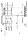
- Fig. 11 shows the contents of the "second reel stopping process”.
- Fig. 11 (a) shows pulses in each phase transmitted from the main CPU 40 to the motor drive circuit 20 during the "stopping process” and the "holding process”.
- Fig. 11(b) shows the rotating speed of the reel 3 relative to time measured when the motor drive circuit 20 drives the stepping motor 70 based on the pulses in each phase received from the main CPU 40.
- the time shown in Fig. 11(b) according to this embodiment corresponds to the time shown in Fig. 10(a).
- the part indicated by the dotted line in Fig. 11 (b) represents the rotating speed of the reel in Fig. 9(b).
- the "second reel stopping process” means the execution of stop control by the main CPU 40 on the stepping motor 70 through two-phase excitation (e.g., the C- and D-phases) when a stop command for the stepping motor 70 is generated according to an operational instruction from the outside, and the damping of vibration of the reel 3 occurring when the reel 3 stops rotating performed by the vibration-suppressing member 75.
- two-phase excitation e.g., the C- and D-phases
- the "symbol process” is performed after a press on the stop button 4; the “excitation process” through two-phase excitation is then performed; “the vibration-suppressing effect by the vibration-suppressing member 75" is then exerted; and the reel 3 is thereafter stopped.
- the “second reel stopping process” includes “vibration-suppressing effect by the vibration-suppressing member 75" which is not included in the “common reel stopping process” as shown in Fig. 8 and also includes the “excitation process” through two-phase excitation.
- the "second reel stopping process” does not include the “deceleration process” in the “first reel stopping process as shown in Fig. 8, the “vibration-suppressing effect by the vibration-suppressing member 75" is exerted.
- the “vibration-suppressing effect by the vibration-suppressing member 75” means damping of any vibration of the reel 3 occurring when the reel 3 stops rotating by the use of the vibration-suppressing means 75.
- a braking time ⁇ t2 and detent torque Td2 of the reel 3 at the "second reel stopping process” can be smaller than the braking time ⁇ t and the detent torque Td at the "common reel stopping process” similarly to the braking time ⁇ t1 and the detent torque Td1 at the "first reel stopping process".
- Fig. 12 shows the contents of the "third reel stopping process”.
- Fig. 12(a) shows pulses in each phase transmitted from the main CPU 40 to the motor drive circuit 20 during the "stopping process” and the "holding process”.
- Fig. 12(b) shows the rotating speed of the reel 3 relative to time measured when the motor drive circuit 20 drives the stepping motor 70 based on the pulses in each phase received from the main CPU 40.
- the time shown in Fig. 12(b) according to this embodiment corresponds to the time shown in Fig. 12(a).
- the part indicated by the dotted line in Fig. 12(b) represents the rotating speed of the reel in Fig. 9(b).
- the "third reel stopping process” means the execution of control by the main CPU 40 to decelerate the stepping motor 70 to a rotating speed lower than its rotating speed during constant speed rotation when a stop command for the stepping motor 70 is generated according to an operational instruction from the outside; the execution of stop control by the main CPU 40 over the stepping motor 70 through two-phase excitation (e.g., the C- and D-phases); and subsequent damping of any vibration of the reel 3 occurring when the reel 3 stops rotating by the vibration-suppressing member 75.
- two-phase excitation e.g., the C- and D-phases
- the "symbol process” is performed after a press on the stop button 4; the “deceleration process” is performed; “excitation process” through two-phase excitation is thereafter performed; and “the vibration-suppressing effect by the vibration-suppressing member 75" is then exerted and the reel 3 is stopped.
- the “third reel stopping process” includes the "vibration-suppressing effect by the vibration-suppressing member 75" which is not included in the “common reel stopping process” and also includes the “deceleration process” and the “excitation process” through two-phase excitation which are not performed in the “common reel stopping process”.
- the processes will not be detailed here because the description will be similar to those presented above.
- a braking time ⁇ t3 and detent torque Td3 of the reel 3 at the "third reel stopping process” can be smaller than the braking time ⁇ t and the detent torque Td at the "common reel stopping process” similarly to the braking time and the detent torque at each of the "first reel stopping process” and the “first reel stopping process”.
- Fig. 13(a) is an actually measured waveform indicating the rotating speed of the reel 3 relative to time during the execution of the "common reel stopping process" (refer to Fig. 8).
- Fig. 13(b) is not a waveform actually measured at any of the "first reel stopping process” through the “third reel stopping process” but is an actually measured waveform indicating the rotating speed of the reel 3 relative to time taken when only the "excitation process through two-phase excitation" is performed.
- Figs. 13 (c) to (e) are actually measured waveforms indicating the rotating speed of the reel 3 relative to time taken when the "first reel stopping process" is performed.
- the "448 pps - deceleration process (224 pps ⁇ 2 pulses) - holding process" shown in Fig. 13 (c) means that a "symbol process” including interrupt processes at intervals of 2.232 ms (the period of a driving frequency of 448 pps) is performed; a "deceleration process” including interrupt processes at 2.232 ms ⁇ 4 (twice the period of a driving frequency of 224 pps) is performed; and a "holding process” is thereafter performed.
- the arrows in Figs. 13 (b) and (e) represent flows similar to that in Fig. 13(c).
- a comparison between the waveform actually measured at the "common reel stopping process” shown in Fig. 13 (a) and the waveform actually measured at the solely performed "excitation process through two-phase excitation” shown in Fig. 13(b) indicates that a braking time ⁇ t1 shown in Fig. 13(b) (the time after the execution of the excitation process until the reel 3 reaches a target stopping position; this equally applies to the following description) is obviously shorter than ⁇ t0 shown in Fig. 13(a).
- a comparison between the waveform actually measured at the solely performed “excitation process through two-phase excitation” shown in Fig. 13(b) and the waveforms actually measured at the "first reel stopping process” shown in Figs. 13(c) to 13(e) indicates that the vibrational amplitudes of the reel 3 shown in Figs. 13(c) to 13(e) are smaller than the vibrational amplitude of the reel 3 shown in Fig. 13(b).
- the execution of the "deceleration process” allows the vibrational amplitude of the reel 3 to be damped more effectively than a stopping process which does not involve this process.
- a comparison between the actually measured waveforms shown in Figs. 13(c) to (e) indicates that the vibrational amplitude of the reel 3 becomes smaller and the damping time of the vibrational amplitude of the reel 3 becomes shorter (from about 300 ms to about 210 ms), as the processing time of the "deceleration process" becomes longer (Fig. 13 (c) - Fig. 13 (d) - Fig. 13(e)). Therefore, the vibrational amplitude of the reel 3 can be made smaller more effectively and the damping time of the vibrational amplitude of the reel 3 can be made shorter, the longer the processing time of the "deceleration process".
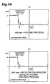
- Figs. 14(a) and (b) are actually measured waveforms indicating rotating speeds of the reel 3 relative to time taken during the execution of the "second reel stopping process” and the “third reel stopping process", respectively.
- Urging forcing applied to the reel 3 in Figs. 14(a) and (b) are 200 gf and 100 gf, respectively.
- the urging forces applied to the reel 3 mean loads applied to the reel 3 by the vibration-suppressing member 75 through the "vibration-suppressing effect by the vibration-suppressing member 75".
- the "448 pps ⁇ holding process" shown in Fig. 14(a) means that a "symbol process” including interrupt processes at intervals of 2.232 ms (the period of a driving frequency of 448 pps) is performed and that a "holding process” is thereafter performed.
- 14(b) means that a "symbol process” including interrupt processes at intervals of 2.232 ms (the period of a driving frequency of 448 pps) is performed; a "deceleration process” including interrupt processes at 2.232 ms ⁇ 4 (twice the period of a driving frequency of 224 pps) is performed; and a "holding process” is thereafter performed.
- the damping time of the vibrational amplitude of the reel 3 at the "second reel stopping process” shown in Fig. 13(a) (448 pups ⁇ holding process) having an urging force (200 gf) to the reel 3 is shorter than the damping time achieved only by the "excitation process through two-phase excitation” shown in Fig. 13(b) (448 pps - holding process) having no urging force to the reel 3 (the damping time in Fig. 14(a) is about 80 ms whereas the damping time in Fig. 13(b) is about 320 ms) .
- the "second reel stopping process” can achieve a damping time shorter than the damping time achieved only by the "excitation process through two-phase excitation” shown in Fig. 13(b) to suppress vibration of the reel 3 more effectively without the deceleration process at the "first reel stopping process".
- the damping time of the vibrational amplitude of the reel 3 at the "third reel stopping process” (shown in Fig. 14(b)) (448 pps - deceleration process (224 pps ⁇ 2 pulses)-holding process) having an urging force (100 gf) to the reel 3 is shorter than the damping time achieved by the "first reel stopping process” shown in Fig.13(c) (448 pups ⁇ deceleration process (224 pps ⁇ 2 pulses) ⁇ holding process) which involves the same deceleration process but has no urging force to the reel 3 (the damping time in Fig. 14(b) is about 80 ms whereas the damping time in Fig.
- the "third reel stopping process” can achieve a further reduction of the damping time from the damping time at the "first reel stopping process” shown in Fig. 13(c) which achieves a reduction of the damping time only insufficiently because the processing time of the deceleration process is short, the process thereby allowing vibration of the reel 3 to be more efficiently suppressed.
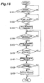
- FIG. 15 shows a flow of control effected by the motor stop control device.
- the process at S108 results in "YES”, and the main CPU 40 performs a winning process (e.g., effect control for displaying a predetermined image on the screen or lamp control for sequentially turning on a plurality of lamps in a predetermined sequence) (S109).
- a winning process e.g., effect control for displaying a predetermined image on the screen or lamp control for sequentially turning on a plurality of lamps in a predetermined sequence
- the main CPU 40 terminates the procedure without executing the process at S109.
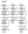
- Fig. 16 is a flow showing details of S105 in Fig. 15.
- Fig. 16 (a) shows a flow of the above-described "first reel stopping process”.
- a "deceleration process" according to this embodiment employs two-phase excitation.
- the main CPU 40 stands by for the start of a "symbol process".
- the main CPU performs a deceleration process to reduce the rotating speed of the reels that are rotating at a constant speed (e.g., 80 rpm) to a lower rotating speed (e.g., 40 rpm), the deceleration process being performed according to an operation of the player on the stop button 4 when the lining-up process is not performed (S202).
- the main CPU 40 outputs pulses for achieving the rotating speed lower than the constant rotating speed to the motor drive circuit 20.
- the main CPU 40 measures the duration of the deceleration process (5203).
- the process at S204 results in "YES”
- the main CPU 40 terminates the deceleration process and executes an excitation process (stop control) through two-phase excitation (e.g., the C- and D-phases) through the motor drive circuit 20 (S205).
- the main CPU 40 measures the duration of the excitation process through two-phase excitation (S206). When a predetermined time passes, the process at S207 results in "YES”, and the main CPU 40 terminates the excitation process through two-phase excitation (stop control) through the motor drive circuit 20 (S208).
- Fig. 16(b) shows a flow of the above-described "second reel stopping process".
- the main CPU 40 stands by for the start of a "symbol process".
- the main CPU performs an excitation process (stop control) through two-phase excitation (e.g., the C- and D-phases) via the motor drive circuit 20, the excitation process being performed according to an operation of the player on the stop button 4 when the lining-up process is not performed (S302). While the excitation process through two-phase excitation is in progress, the vibration-suppressing effect is exerted by the vibration-suppressing member 75 in parallel.
- the main CPU 40 measures the duration of the excitation process through two-phase excitation (S303). When a predetermined time passes, the process at S304 results in "YES", and the main CPU 40 terminates the excitation process through two-phase excitation (stop control) through the motor drive circuit 20 (S305).
- the vibration-suppressing effect of the vibration-suppressing member 75 terminates at the same time when the reels 3 stop because it is a mechanical braking mechanism.
- Fig. 16(c) shows a flow of the above-described "third reel stopping process".
- the vibration-suppressing effect of the vibration-suppressing member 75 is exerted in parallel with the "first reel stopping process” shown in Fig. 16(a). Since the flow of the "third reel stopping process” is therefore similar to the flow of the "first reel stopping process” described above, no detail will be given on the flow.
- the deceleration transmission mechanism 700 transmits the rotation of the stepping motor 70 to the rotating shaft for rotating the reels 3 at a predetermined reduction ratio, a designer can adopt a low cost stepping motor having small rotational torque.
- the main CPU 40 executes stop control through two-phase excitation over the stepping motor 70 after executing control for reducing the rotating speed of the stepping motor 70, the main CPU 40 can stop the reels 3 at accurate positions. Further, since the main CPU 40 can execute stop control of the stepping motor using only two-phase excitation, the main CPU 40 can stop the reels 3 at more accurate positions.
- the main CPU 40 executes control for reducing the rotating speed of the stepping motor 70, the main CPU 40 can stop the reels 3 at accurate positions with a less reduction in the smoothness of braking of the stepping motor 70 than in reducing the rotating speed of the stepping motor 70 abruptly.
- the stopping of the reel 3 is not dependent upon braking with detent torque, no balance adjustment as described above is required at the time of manufacture, which allows operators to manufacture reel units with a smaller number of steps.
- the vibration-suppressing member 75 since the vibration-suppressing member 75 is always urged against the reels 3, the vibration-suppressing member 75 can damp any vibration of the reels 3 when the reels 3 stop rotating. As a result, the vibration-suppressing member 75 allows the reels 3 to be stopped at accurate positions without reducing the smoothness of braking of the stepping motor 70. Since no balance adjustment as described above is required at the time of manufacture because of the provision of the vibration-suppressing member 75, operators can manufacture reel units with a smaller number of steps.
- the invention is not limited to the above embodiment and may be modified as described below.
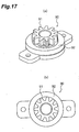
- the modification includes an oil damper 90 instead of the vibration-suppressing member 75 according to the above-described embodiment.
- Fig. 17 shows a perspective view of the oil damper 90 according to this embodiment.
- the oil damper 90 has a rotating portion 91 and a base portion 92.
- An oil having predetermined viscosity is charged in the base portion 92.
- a rotating force of the rotating portion 91 is buffered by the oil charged in the base portion 92.
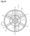
- Fig. 18 shows a positional relationship of the oil damper according to this modification.
- the oil damper 90 is disposed inside a reel 3 such that a gear formed at the rotating portion 91 is in contact with the input-side gear 92, as shown in Fig. 18.
- the rotating force of the rotating portion 91 is moderated by the oil charged in the base portion 92 (a buffering force).
- the oil damper 90 since the gear formed at the rotating portion 91 is in contact with the input-side gear 72, the oil damper 90 exhibits a braking function when the reel 3 stops rotating because of the buffering force of the rotating portion 91.
- the oil damper 90 allows vibration of the reel 3 occurring when the stepping motor 70 is braked (or at the time of backlash) to be damped quickly.
- the invention is not limited to the above-described embodiment and may be modified as described below.
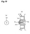
- the modification includes a felt 751, a high-friction member such as rubber, or a wave washer 752 instead of the vibration-suppressing member 75 according to the above embodiment.
- Fig. 19(a) shows a configuration of the felt 751 taken from the above.
- Fig. 19 (b) shows a positional relationship in which the felt 751 is provided.
- the felt 751 is in a circular shape and is formed with a hole in which the fastening member 73 can be inserted in the middle thereof.
- the felt 751 is removal-stopped by the fastening member 73.
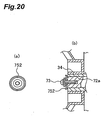
- Fig. 20(a) shows a configuration of the wave washer 752 taken from the above.
- Fig. 20(b) shows a positional relationship in which the wave washer 752 is provided.
- the wave washer 752 is in a planar shape having waves traveling outward from the center and is formed with a hole in which the fastening member 73 can be inserted in the middle thereof.
- the wave washer 752 is removal-stopped by the fastening member 73.
- a high-friction member including the felt 751 and the wave washer 752 removal-stopped by the fastening member 73 can damp any vibration of the reel 3 occurring at the time of braking because of the frictional force of the high-friction member.
- the invention is not limited to the above-described embodiment and may be modified as described below.
- the output-side gear 71 and the input-side gear 72 of the above-described embodiment are formed by rubber rollers 711 and 721.
- Fig. 21 shows a positional relationship in which the rubber rollers 711 and 721 are provided.
- the two rubber rollers 711 and 721 are in contact with each other and transmit rotation without slip because of their high frictional coefficient.
- the two rubber rollers 711 and 721 are disposed inside a reel 3.
- This modification may have a configuration in which an expandable and contractible belt 723 formed by a soft member including rubber or urethane is stretched around an output-side pulley 71 and an input-side pulley 72 instead of the output-side gear 71 and the input-side gear 72 formed by spur gears.
- Fig. 22 shows a positional relationship in which the output-side pulley 71, the input-side pulley 72 formed of rubber and the belt 723 are provided. Both of the output-side pulley 71 and the input-side pulley 72 rotate as the belt 72 stretched around the output-side pulley 71 and the input-side pulley 72 rotates.
- the belt 72 formed by a soft member expands and contracts to absorb the vibration.
- either of the output-side gear 71 and the input-side gear 72 formed by spur gears may be a scissors gear.
- backlash of the gears can be eliminated to provide a configuration that is unlikely to vibrate, and the output-side gear or input-side gear formed by a scissors gear can absorb any vibration occurring at the shaft of the reel 3 at the time of braking of the stepping motor 70.
- the material of the spur gears may be changed to soft members such as polyamide.
- the spur gears comprising soft members undergo elastic deformation to allow any vibration occurring at the shaft of the reel 3 to be absorbed.
- a decelerating process is added to stop control over the stepping motor 70 which rotates at a constant speed, but the invention is not limited to rotation at a constant speed.
- a deceleration process may be performed for stop control of a reel 3 whose rotating speed varies between 60 rpm and 80 rpm.
- a PM type is used as the stepping motor 70 in this embodiment, this is not limiting the invention, and a hybrid type may be used in the direct driving method.
- the invention makes it possible to reduce the cost of a stepping motor, to manufacture a reel unit with a small number of steps, and to stop reels at accurate positions without reducing the smoothness of braking of a stepping motor.
Landscapes
- Physics & Mathematics (AREA)
- General Physics & Mathematics (AREA)
- Engineering & Computer Science (AREA)
- Power Engineering (AREA)
- Slot Machines And Peripheral Devices (AREA)
- Control Of Stepping Motors (AREA)
- Output Control And Ontrol Of Special Type Engine (AREA)
- Power-Operated Mechanisms For Wings (AREA)
- Stopping Of Electric Motors (AREA)
- Power Steering Mechanism (AREA)
- Display Devices Of Pinball Game Machines (AREA)
- Pinball Game Machines (AREA)
- Control Of Throttle Valves Provided In The Intake System Or In The Exhaust System (AREA)
Claims (2)
- Eine Motoranhaltesteuerungsvorrichtung für eine Spielmaschine vom Drehwalzentyp, die einen Schrittmotor (70) einschließt, mit zwei Paaren von Erregungsphasen als eine Antriebsquelle einer Walze (3) mit einer Mehrzahl von darauf bezeichneten Symbolen, und in der der Motor gemäß einer Betriebsanweisung von außerhalb (4) angehalten wird, wobei die Motoranhaltesteuerungsvorrichtung umfasst:einen Abbremsübermittlungsmechanismus (700; 71, 72) zum Übermitteln der Drehung des Motors auf eine drehende Welle zum Drehen der Walze bei einem vorbestimmten Untersetzungsverhältnis;Motoranhaltesteuerungsmittel (40) zum Durchführen einer Anhaltesteuerung des Motors (70) durch Zwei-Phasenerregung, wenn ein Motoranhaltebefehl gemäß der Betriebsanweisung von außerhalb (4) erzeugt wird; undein Schwingungsunterdrückungsteil (90) zum Dämpfen einer Schwingung der Walze, die auftritt, wenn die Drehung der Walze durch die Anhaltesteuerung des Motoranhaltesteuerungsmittels angehalten wird,dadurch gekennzeichnet:dass der Abbremsübermittlungsmechanismus (700; 71, 72) ein auf einer Antriebsseite des Schrittmotors (70) bereitgestelltes ausgangsseitiges Getriebe (71), und ein derart an der Walze angeordnetes eingangsseitiges Getriebe (72) aufweist, dass das eingangsseitige Getriebe in Kontakt mit dem ausgangsseitigen Getriebe und koaxial mit der Drehwelle der Walze (3) ist;das Schwingungsunterdrückungsteil (90) ein Öldämpfer (90) ist, mit einem Basisteil (92), in den ein Öl geladen ist, und einem Drehteil (91) mit einem Getriebe, das mit dem eingangsseitigen Getriebe (72) in Kontakt ist, wobei eine Drehkraft des drehenden Teils (91) durch das in dem Basisteil (92) geladenen Öl moderierbar ist; unddas Motoranhaltesteuerungsmittel (40) angepasst ist zum Durchführen einer Anhaltesteuerung parallel mit dem Schwingungsunterdrückungseffekt des Schwingungsunterdrückungsteils (90).
- Motoranhaltesteuerungsvorrichtung gemäß Anspruch 1, wobei das Motoranhaltesteuerungsmittel (40) angepasst ist zum Durchführen der Anhaltesteuerung durch eine Zwei-Phasenerregung durch Übermitteln von Pulsen in einer Anzahl entsprechend einem vorbestimmten Zeitintervall.
Applications Claiming Priority (2)
| Application Number | Priority Date | Filing Date | Title |
|---|---|---|---|
| JP2003131411 | 2003-05-09 | ||
| JP2003131411 | 2003-05-09 |
Publications (2)
| Publication Number | Publication Date |
|---|---|
| EP1475758A1 EP1475758A1 (de) | 2004-11-10 |
| EP1475758B1 true EP1475758B1 (de) | 2006-06-21 |
Family
ID=32985668
Family Applications (2)
| Application Number | Title | Priority Date | Filing Date |
|---|---|---|---|
| EP04004712A Expired - Lifetime EP1475758B1 (de) | 2003-05-09 | 2004-03-01 | Vorrichtung zum Anhalten eines Motors |
| EP04010970A Expired - Lifetime EP1475759B1 (de) | 2003-05-09 | 2004-05-07 | Regelungsvorrichtung zum Anhalten eines Motors |
Family Applications After (1)
| Application Number | Title | Priority Date | Filing Date |
|---|---|---|---|
| EP04010970A Expired - Lifetime EP1475759B1 (de) | 2003-05-09 | 2004-05-07 | Regelungsvorrichtung zum Anhalten eines Motors |
Country Status (8)
| Country | Link |
|---|---|
| US (2) | US6998805B2 (de) |
| EP (2) | EP1475758B1 (de) |
| CN (2) | CN100448157C (de) |
| AT (2) | ATE331264T1 (de) |
| AU (2) | AU2004200890A1 (de) |
| DE (2) | DE602004001279T2 (de) |
| ES (2) | ES2266936T3 (de) |
| ZA (2) | ZA200401686B (de) |
Families Citing this family (21)
| Publication number | Priority date | Publication date | Assignee | Title |
|---|---|---|---|---|
| JP2004215720A (ja) * | 2003-01-09 | 2004-08-05 | Aruze Corp | 遊技機 |
| US6998805B2 (en) * | 2003-05-09 | 2006-02-14 | Aruze Corp. | Motor stop control device |
| JP4414716B2 (ja) * | 2003-10-02 | 2010-02-10 | 株式会社ユニバーサルエンターテインメント | モータ停止制御装置 |
| JP2005137765A (ja) * | 2003-11-10 | 2005-06-02 | Aruze Corp | リールユニット |
| JP2005143833A (ja) | 2003-11-14 | 2005-06-09 | Aruze Corp | モータ駆動装置 |
| US7371172B2 (en) * | 2004-09-08 | 2008-05-13 | Igt | Symbol display device for game machine |
| US8047910B2 (en) * | 2005-08-31 | 2011-11-01 | Bally Gaming, Inc. | Gaming machines having rhythmic reels |
| JP4200161B2 (ja) * | 2005-12-28 | 2008-12-24 | ミネベアモータ株式会社 | 振動発生用ステッピングモータの停止制御方法および停止制御装置 |
| US20080045314A1 (en) * | 2006-08-18 | 2008-02-21 | Aruze Gaming America, Inc. | Slot machine and playing method thereof |
| US7624985B2 (en) * | 2006-12-05 | 2009-12-01 | Konami Gaming Incorporated | Reel assembly and gaming machine comprising the same |
| AU2008229938A1 (en) * | 2007-10-17 | 2009-05-07 | Aristocrat Technologies Australia Pty Limited | A gaming system and a method of gaming |
| AU2009201719A1 (en) | 2008-05-05 | 2009-11-19 | Aristocrat Technologies Australia Pty Limited | A method of gaming and a gaming system |
| US7850171B2 (en) * | 2008-10-23 | 2010-12-14 | Igt | Gaming system, device and method involving a plurality of rotors interchangeably operable in a decoupled mode and a coupled mode |
| JP2012100875A (ja) * | 2010-11-10 | 2012-05-31 | Universal Entertainment Corp | ゲーミングマシン |
| EP2466400B1 (de) * | 2010-12-16 | 2019-01-16 | The Swatch Group Research and Development Ltd. | Trägheitsbewegung eines mechanischen anzeigeorgans |
| US8918484B2 (en) | 2011-03-17 | 2014-12-23 | Charles Moncavage | System and method for recording and sharing music |
| US9659437B2 (en) | 2012-09-28 | 2017-05-23 | Bally Gaming, Inc. | System and method for cross platform persistent gaming sessions using a mobile device |
| US8628084B1 (en) | 2013-03-02 | 2014-01-14 | Wms Gaming Inc. | Gaming machine having hub-less reels |
| US20190122487A1 (en) * | 2017-10-24 | 2019-04-25 | King Show Games Inc. | Reel-based wagering games |
| CN111510032A (zh) * | 2020-04-27 | 2020-08-07 | 桂林恒毅金宇通信技术有限公司 | 一种步进电机去抖动的方法 |
| US11443584B1 (en) | 2021-03-24 | 2022-09-13 | Igt | Locking links |
Family Cites Families (36)
| Publication number | Priority date | Publication date | Assignee | Title |
|---|---|---|---|---|
| GB546288A (en) | 1940-12-30 | 1942-07-06 | Blackburn Aircraft Ltd | Improvements in aircraft arrester gear |
| US3733075A (en) * | 1970-05-07 | 1973-05-15 | Waukegan Electronics | Device for displaying randomly selected symbol combinations and randomly operative player operated symbol changing means therefor |
| JPS6012879B2 (ja) * | 1974-06-06 | 1985-04-03 | 株式会社リコー | ステツプモ−タの自励駆動装置 |
| GB1471866A (en) | 1974-06-27 | 1977-04-27 | Shaw A | Gaming machine |
| US4071246A (en) * | 1976-08-18 | 1978-01-31 | Bally Manufacturing Corporation | Magnetic reel reading device |
| SU736335A1 (ru) | 1977-11-16 | 1980-05-25 | Предприятие П/Я Х-5827 | Устройство дл управлени четырехфазным шаговым двигателем с резервированием |
| GB2059520A (en) | 1979-10-01 | 1981-04-23 | Crompton A | A Two-speed Drive Mechanism |
| SU864481A1 (ru) | 1979-12-07 | 1981-09-15 | Предприятие П/Я В-2739 | Устройство дл управлени четырехфазным реверсивным шаговым электродвигателем |
| US4363486A (en) * | 1980-10-30 | 1982-12-14 | Chaudhry Jagdish C | Electronic gaming apparatus |
| JPS5889088U (ja) * | 1981-12-10 | 1983-06-16 | 株式会社ユニバ−サル | スロツトマシン用リ−ル |
| US4625931A (en) * | 1982-08-27 | 1986-12-02 | Kabushiki Kaisha Sato | Web-meandering preventing device |
| JPS5941198A (ja) * | 1982-08-30 | 1984-03-07 | Tokyo Electric Co Ltd | ステツピングモ−タ駆動装置 |
| JPS59185073A (ja) * | 1983-04-01 | 1984-10-20 | Teac Co | 磁気デイスク駆動装置 |
| GB2150335A (en) | 1983-11-07 | 1985-06-26 | Gutierrez Arturo Martin | Gaming machine |
| JPS60214473A (ja) * | 1984-04-09 | 1985-10-26 | Mitsubishi Electric Corp | 磁気デイスク装置のロ−デイング機構 |
| US4711452A (en) * | 1984-10-24 | 1987-12-08 | International Game Technology (Igt) | Amusement machine |
| JPH0532145Y2 (de) * | 1985-08-23 | 1993-08-18 | ||
| JP2666936B2 (ja) | 1987-11-13 | 1997-10-22 | 株式会社シグマ | スロットマシンのリール駆動装置 |
| JPH02188196A (ja) * | 1989-01-13 | 1990-07-24 | Copal Co Ltd | ステッピングモータの駆動制御方法 |
| US4888749A (en) | 1989-01-30 | 1989-12-19 | Timex Corporation | Three hand movement for a timepiece having a stepping motor |
| JPH06319296A (ja) | 1993-05-06 | 1994-11-15 | Tamagawa Seiki Co Ltd | パチスロ用ステップモータの制御方法 |
| JP2654364B2 (ja) * | 1994-12-22 | 1997-09-17 | 株式会社イーグル | スロットマシン |
| JPH0910388A (ja) * | 1995-06-29 | 1997-01-14 | Amtex:Kk | 手振れ防止パチンコ機発射ハンドル |
| JPH09327553A (ja) | 1996-06-11 | 1997-12-22 | Samii Kk | パチンコ機用の図柄変動表示装置 |
| JP3897840B2 (ja) | 1996-08-30 | 2007-03-28 | アルゼ株式会社 | リールユニット |
| KR100260021B1 (ko) * | 1996-09-20 | 2000-06-15 | 김민박 | 차량용 모터 |
| JP3222828B2 (ja) * | 1998-02-17 | 2001-10-29 | 株式会社ウエスト・シー | スロットマシン |
| RU2133550C1 (ru) | 1998-03-03 | 1999-07-20 | Акционерное общество открытого типа Ракетно-космическая корпорация "Энергия" им.С.П.Королева | Распределитель импульсов для управления четырехфазным шаговым двигателем |
| JP2001224773A (ja) * | 2000-02-17 | 2001-08-21 | Uingu:Kk | 遊技機用シンボル表示装置 |
| JP3911123B2 (ja) | 2000-11-29 | 2007-05-09 | アビリット株式会社 | リール駆動用ステッピングモータの停止制御方法 |
| JP4227323B2 (ja) | 2001-10-19 | 2009-02-18 | 株式会社三共 | スロットマシン |
| JP2003144642A (ja) * | 2001-11-16 | 2003-05-20 | Heiwa Corp | 遊技機部品 |
| US20040018869A1 (en) * | 2002-02-06 | 2004-01-29 | Fumio Inoue | Symbol display device for game machine |
| JP2004105541A (ja) * | 2002-09-19 | 2004-04-08 | Sayama Precision Ind Co | スロットマシン |
| JP2004141521A (ja) * | 2002-10-28 | 2004-05-20 | Abilit Corp | 遊技機用ハンドルおよびこれを備えた遊技機 |
| US6998805B2 (en) * | 2003-05-09 | 2006-02-14 | Aruze Corp. | Motor stop control device |
-
2003
- 2003-10-31 US US10/697,085 patent/US6998805B2/en not_active Expired - Lifetime
-
2004
- 2004-03-01 AT AT04004712T patent/ATE331264T1/de not_active IP Right Cessation
- 2004-03-01 AU AU2004200890A patent/AU2004200890A1/en not_active Abandoned
- 2004-03-01 DE DE602004001279T patent/DE602004001279T2/de not_active Expired - Lifetime
- 2004-03-01 EP EP04004712A patent/EP1475758B1/de not_active Expired - Lifetime
- 2004-03-01 ZA ZA2004/01686A patent/ZA200401686B/en unknown
- 2004-03-01 ES ES04004712T patent/ES2266936T3/es not_active Expired - Lifetime
- 2004-03-19 CN CNB2004100294726A patent/CN100448157C/zh not_active Expired - Fee Related
- 2004-04-29 US US10/834,182 patent/US7038411B2/en not_active Expired - Lifetime
- 2004-05-04 AU AU2004201871A patent/AU2004201871A1/en not_active Abandoned
- 2004-05-07 EP EP04010970A patent/EP1475759B1/de not_active Expired - Lifetime
- 2004-05-07 AT AT04010970T patent/ATE368269T1/de active
- 2004-05-07 ZA ZA200403488A patent/ZA200403488B/xx unknown
- 2004-05-07 ES ES04010970T patent/ES2289390T3/es not_active Expired - Lifetime
- 2004-05-07 DE DE602004007713T patent/DE602004007713T2/de not_active Expired - Lifetime
- 2004-05-09 CN CN200410043470.2A patent/CN1255772C/zh not_active Expired - Fee Related
Also Published As
| Publication number | Publication date |
|---|---|
| AU2004201871A1 (en) | 2004-11-25 |
| US7038411B2 (en) | 2006-05-02 |
| EP1475758A1 (de) | 2004-11-10 |
| ZA200403488B (en) | 2005-01-04 |
| ES2289390T3 (es) | 2008-02-01 |
| DE602004007713D1 (de) | 2007-09-06 |
| CN1716751A (zh) | 2006-01-04 |
| ZA200401686B (en) | 2005-06-29 |
| EP1475759B1 (de) | 2007-07-25 |
| US6998805B2 (en) | 2006-02-14 |
| DE602004001279T2 (de) | 2007-06-06 |
| ATE331264T1 (de) | 2006-07-15 |
| US20040222760A1 (en) | 2004-11-11 |
| EP1475759A1 (de) | 2004-11-10 |
| DE602004001279D1 (de) | 2006-08-03 |
| DE602004007713T2 (de) | 2008-04-30 |
| CN100448157C (zh) | 2008-12-31 |
| AU2004200890A1 (en) | 2004-11-25 |
| CN1550245A (zh) | 2004-12-01 |
| CN1255772C (zh) | 2006-05-10 |
| ES2266936T3 (es) | 2007-03-01 |
| ATE368269T1 (de) | 2007-08-15 |
| US20040224752A1 (en) | 2004-11-11 |
Similar Documents
| Publication | Publication Date | Title |
|---|---|---|
| EP1475758B1 (de) | Vorrichtung zum Anhalten eines Motors | |
| JP2004358216A (ja) | モータ停止制御装置、及び、遊技機 | |
| US7019475B2 (en) | Motor stop control device for gaming machine and gaming machine provided with the motor stop control device | |
| JP3911123B2 (ja) | リール駆動用ステッピングモータの停止制御方法 | |
| JP5747284B2 (ja) | 遊技機 | |
| JP5889043B2 (ja) | 遊技機 | |
| JP5812331B2 (ja) | 遊技機 | |
| US6998806B2 (en) | Motor stop control device for gaming machine and gaming machine with the same | |
| CN100406083C (zh) | 电动机驱动装置 | |
| JP2015019825A (ja) | 遊技機 | |
| JP4553174B2 (ja) | スロットマシン | |
| EP1727271A2 (de) | Schrittmotorsteuerung und Spielautomat | |
| JP5658949B2 (ja) | 遊技機 | |
| JP5577517B2 (ja) | 遊技機 | |
| JP2005094910A (ja) | モータ停止制御装置 | |
| JP2005006838A (ja) | リール駆動装置 | |
| JP2005230090A (ja) | モータ駆動装置 | |
| JP7037386B2 (ja) | スロットマシン | |
| JP6870830B2 (ja) | 遊技機 |
Legal Events
| Date | Code | Title | Description |
|---|---|---|---|
| PUAI | Public reference made under article 153(3) epc to a published international application that has entered the european phase |
Free format text: ORIGINAL CODE: 0009012 |
|
| 17P | Request for examination filed |
Effective date: 20040301 |
|
| AK | Designated contracting states |
Kind code of ref document: A1 Designated state(s): AT BE BG CH CY CZ DE DK EE ES FI FR GB GR HU IE IT LI LU MC NL PL PT RO SE SI SK TR |
|
| AX | Request for extension of the european patent |
Extension state: AL LT LV MK |
|
| 17Q | First examination report despatched |
Effective date: 20041216 |
|
| AKX | Designation fees paid |
Designated state(s): AT BE BG CH CY CZ DE DK EE ES FI FR GB GR HU IE IT LI LU MC NL PL PT RO SE SI SK TR |
|
| GRAP | Despatch of communication of intention to grant a patent |
Free format text: ORIGINAL CODE: EPIDOSNIGR1 |
|
| GRAS | Grant fee paid |
Free format text: ORIGINAL CODE: EPIDOSNIGR3 |
|
| GRAA | (expected) grant |
Free format text: ORIGINAL CODE: 0009210 |
|
| AK | Designated contracting states |
Kind code of ref document: B1 Designated state(s): AT BE BG CH CY CZ DE DK EE ES FI FR GB GR HU IE IT LI LU MC NL PL PT RO SE SI SK TR |
|
| PG25 | Lapsed in a contracting state [announced via postgrant information from national office to epo] |
Ref country code: IT Free format text: LAPSE BECAUSE OF FAILURE TO SUBMIT A TRANSLATION OF THE DESCRIPTION OR TO PAY THE FEE WITHIN THE PRESCRIBED TIME-LIMIT;WARNING: LAPSES OF ITALIAN PATENTS WITH EFFECTIVE DATE BEFORE 2007 MAY HAVE OCCURRED AT ANY TIME BEFORE 2007. THE CORRECT EFFECTIVE DATE MAY BE DIFFERENT FROM THE ONE RECORDED. Effective date: 20060621 Ref country code: FI Free format text: LAPSE BECAUSE OF FAILURE TO SUBMIT A TRANSLATION OF THE DESCRIPTION OR TO PAY THE FEE WITHIN THE PRESCRIBED TIME-LIMIT Effective date: 20060621 Ref country code: AT Free format text: LAPSE BECAUSE OF FAILURE TO SUBMIT A TRANSLATION OF THE DESCRIPTION OR TO PAY THE FEE WITHIN THE PRESCRIBED TIME-LIMIT Effective date: 20060621 Ref country code: NL Free format text: LAPSE BECAUSE OF FAILURE TO SUBMIT A TRANSLATION OF THE DESCRIPTION OR TO PAY THE FEE WITHIN THE PRESCRIBED TIME-LIMIT Effective date: 20060621 Ref country code: RO Free format text: LAPSE BECAUSE OF FAILURE TO SUBMIT A TRANSLATION OF THE DESCRIPTION OR TO PAY THE FEE WITHIN THE PRESCRIBED TIME-LIMIT Effective date: 20060621 Ref country code: SI Free format text: LAPSE BECAUSE OF FAILURE TO SUBMIT A TRANSLATION OF THE DESCRIPTION OR TO PAY THE FEE WITHIN THE PRESCRIBED TIME-LIMIT Effective date: 20060621 Ref country code: BE Free format text: LAPSE BECAUSE OF FAILURE TO SUBMIT A TRANSLATION OF THE DESCRIPTION OR TO PAY THE FEE WITHIN THE PRESCRIBED TIME-LIMIT Effective date: 20060621 Ref country code: SK Free format text: LAPSE BECAUSE OF FAILURE TO SUBMIT A TRANSLATION OF THE DESCRIPTION OR TO PAY THE FEE WITHIN THE PRESCRIBED TIME-LIMIT Effective date: 20060621 Ref country code: CH Free format text: LAPSE BECAUSE OF FAILURE TO SUBMIT A TRANSLATION OF THE DESCRIPTION OR TO PAY THE FEE WITHIN THE PRESCRIBED TIME-LIMIT Effective date: 20060621 Ref country code: LI Free format text: LAPSE BECAUSE OF FAILURE TO SUBMIT A TRANSLATION OF THE DESCRIPTION OR TO PAY THE FEE WITHIN THE PRESCRIBED TIME-LIMIT Effective date: 20060621 Ref country code: CZ Free format text: LAPSE BECAUSE OF FAILURE TO SUBMIT A TRANSLATION OF THE DESCRIPTION OR TO PAY THE FEE WITHIN THE PRESCRIBED TIME-LIMIT Effective date: 20060621 Ref country code: PL Free format text: LAPSE BECAUSE OF FAILURE TO SUBMIT A TRANSLATION OF THE DESCRIPTION OR TO PAY THE FEE WITHIN THE PRESCRIBED TIME-LIMIT Effective date: 20060621 |
|
| REG | Reference to a national code |
Ref country code: GB Ref legal event code: FG4D |
|
| REG | Reference to a national code |
Ref country code: CH Ref legal event code: EP |
|
| REG | Reference to a national code |
Ref country code: IE Ref legal event code: FG4D |
|
| REF | Corresponds to: |
Ref document number: 602004001279 Country of ref document: DE Date of ref document: 20060803 Kind code of ref document: P |
|
| PG25 | Lapsed in a contracting state [announced via postgrant information from national office to epo] |
Ref country code: DK Free format text: LAPSE BECAUSE OF FAILURE TO SUBMIT A TRANSLATION OF THE DESCRIPTION OR TO PAY THE FEE WITHIN THE PRESCRIBED TIME-LIMIT Effective date: 20060921 Ref country code: SE Free format text: LAPSE BECAUSE OF FAILURE TO SUBMIT A TRANSLATION OF THE DESCRIPTION OR TO PAY THE FEE WITHIN THE PRESCRIBED TIME-LIMIT Effective date: 20060921 |
|
| PG25 | Lapsed in a contracting state [announced via postgrant information from national office to epo] |
Ref country code: PT Free format text: LAPSE BECAUSE OF FAILURE TO SUBMIT A TRANSLATION OF THE DESCRIPTION OR TO PAY THE FEE WITHIN THE PRESCRIBED TIME-LIMIT Effective date: 20061121 |
|
| NLV1 | Nl: lapsed or annulled due to failure to fulfill the requirements of art. 29p and 29m of the patents act | ||
| REG | Reference to a national code |
Ref country code: CH Ref legal event code: PL |
|
| ET | Fr: translation filed | ||
| REG | Reference to a national code |
Ref country code: ES Ref legal event code: FG2A Ref document number: 2266936 Country of ref document: ES Kind code of ref document: T3 |
|
| PLBE | No opposition filed within time limit |
Free format text: ORIGINAL CODE: 0009261 |
|
| STAA | Information on the status of an ep patent application or granted ep patent |
Free format text: STATUS: NO OPPOSITION FILED WITHIN TIME LIMIT |
|
| 26N | No opposition filed |
Effective date: 20070322 |
|
| PG25 | Lapsed in a contracting state [announced via postgrant information from national office to epo] |
Ref country code: MC Free format text: LAPSE BECAUSE OF NON-PAYMENT OF DUE FEES Effective date: 20070331 Ref country code: IE Free format text: LAPSE BECAUSE OF NON-PAYMENT OF DUE FEES Effective date: 20070301 |
|
| PG25 | Lapsed in a contracting state [announced via postgrant information from national office to epo] |
Ref country code: GR Free format text: LAPSE BECAUSE OF FAILURE TO SUBMIT A TRANSLATION OF THE DESCRIPTION OR TO PAY THE FEE WITHIN THE PRESCRIBED TIME-LIMIT Effective date: 20060922 |
|
| PG25 | Lapsed in a contracting state [announced via postgrant information from national office to epo] |
Ref country code: BG Free format text: LAPSE BECAUSE OF FAILURE TO SUBMIT A TRANSLATION OF THE DESCRIPTION OR TO PAY THE FEE WITHIN THE PRESCRIBED TIME-LIMIT Effective date: 20060921 |
|
| PG25 | Lapsed in a contracting state [announced via postgrant information from national office to epo] |
Ref country code: EE Free format text: LAPSE BECAUSE OF FAILURE TO SUBMIT A TRANSLATION OF THE DESCRIPTION OR TO PAY THE FEE WITHIN THE PRESCRIBED TIME-LIMIT Effective date: 20060621 |
|
| PG25 | Lapsed in a contracting state [announced via postgrant information from national office to epo] |
Ref country code: LU Free format text: LAPSE BECAUSE OF NON-PAYMENT OF DUE FEES Effective date: 20070301 Ref country code: CY Free format text: LAPSE BECAUSE OF FAILURE TO SUBMIT A TRANSLATION OF THE DESCRIPTION OR TO PAY THE FEE WITHIN THE PRESCRIBED TIME-LIMIT Effective date: 20060621 |
|
| PG25 | Lapsed in a contracting state [announced via postgrant information from national office to epo] |
Ref country code: HU Free format text: LAPSE BECAUSE OF FAILURE TO SUBMIT A TRANSLATION OF THE DESCRIPTION OR TO PAY THE FEE WITHIN THE PRESCRIBED TIME-LIMIT Effective date: 20061222 Ref country code: TR Free format text: LAPSE BECAUSE OF FAILURE TO SUBMIT A TRANSLATION OF THE DESCRIPTION OR TO PAY THE FEE WITHIN THE PRESCRIBED TIME-LIMIT Effective date: 20060621 |
|
| REG | Reference to a national code |
Ref country code: ES Ref legal event code: PC2A Owner name: UNIVERSAL ENTERTAINMENT CORPORATION Effective date: 20120207 |
|
| REG | Reference to a national code |
Ref country code: DE Ref legal event code: R082 Ref document number: 602004001279 Country of ref document: DE Representative=s name: HOFFMANN - EITLE, DE |
|
| PGFP | Annual fee paid to national office [announced via postgrant information from national office to epo] |
Ref country code: FR Payment date: 20120403 Year of fee payment: 9 |
|
| REG | Reference to a national code |
Ref country code: DE Ref legal event code: R081 Ref document number: 602004001279 Country of ref document: DE Owner name: UNIVERSAL ENTERTAINMENT CORP., JP Free format text: FORMER OWNER: ARUZE CORP., TOKIO/TOKYO, JP Effective date: 20120423 Ref country code: DE Ref legal event code: R082 Ref document number: 602004001279 Country of ref document: DE Representative=s name: HOFFMANN - EITLE, DE Effective date: 20120423 Ref country code: DE Ref legal event code: R082 Ref document number: 602004001279 Country of ref document: DE Representative=s name: HOFFMANN - EITLE PATENT- UND RECHTSANWAELTE PA, DE Effective date: 20120423 |
|
| PGFP | Annual fee paid to national office [announced via postgrant information from national office to epo] |
Ref country code: IT Payment date: 20120327 Year of fee payment: 9 |
|
| PGFP | Annual fee paid to national office [announced via postgrant information from national office to epo] |
Ref country code: ES Payment date: 20120327 Year of fee payment: 9 |
|
| REG | Reference to a national code |
Ref country code: FR Ref legal event code: ST Effective date: 20131129 |
|
| PG25 | Lapsed in a contracting state [announced via postgrant information from national office to epo] |
Ref country code: FR Free format text: LAPSE BECAUSE OF NON-PAYMENT OF DUE FEES Effective date: 20130402 |
|
| PG25 | Lapsed in a contracting state [announced via postgrant information from national office to epo] |
Ref country code: IT Free format text: LAPSE BECAUSE OF NON-PAYMENT OF DUE FEES Effective date: 20130301 |
|
| REG | Reference to a national code |
Ref country code: ES Ref legal event code: FD2A Effective date: 20140606 |
|
| PG25 | Lapsed in a contracting state [announced via postgrant information from national office to epo] |
Ref country code: ES Free format text: LAPSE BECAUSE OF NON-PAYMENT OF DUE FEES Effective date: 20130302 |
|
| PGFP | Annual fee paid to national office [announced via postgrant information from national office to epo] |
Ref country code: GB Payment date: 20160321 Year of fee payment: 13 |
|
| PGFP | Annual fee paid to national office [announced via postgrant information from national office to epo] |
Ref country code: DE Payment date: 20160330 Year of fee payment: 13 |
|
| REG | Reference to a national code |
Ref country code: DE Ref legal event code: R119 Ref document number: 602004001279 Country of ref document: DE |
|
| GBPC | Gb: european patent ceased through non-payment of renewal fee |
Effective date: 20170301 |
|
| PG25 | Lapsed in a contracting state [announced via postgrant information from national office to epo] |
Ref country code: DE Free format text: LAPSE BECAUSE OF NON-PAYMENT OF DUE FEES Effective date: 20171003 |
|
| PG25 | Lapsed in a contracting state [announced via postgrant information from national office to epo] |
Ref country code: GB Free format text: LAPSE BECAUSE OF NON-PAYMENT OF DUE FEES Effective date: 20170301 |