EP1475342B1 - Vorrichtung zur Einrichtung eines temporären Schutzraumes für Aufzüge - Google Patents
Vorrichtung zur Einrichtung eines temporären Schutzraumes für Aufzüge Download PDFInfo
- Publication number
- EP1475342B1 EP1475342B1 EP04010417A EP04010417A EP1475342B1 EP 1475342 B1 EP1475342 B1 EP 1475342B1 EP 04010417 A EP04010417 A EP 04010417A EP 04010417 A EP04010417 A EP 04010417A EP 1475342 B1 EP1475342 B1 EP 1475342B1
- Authority
- EP
- European Patent Office
- Prior art keywords
- speed limiter
- fastened
- cage
- limiter cable
- shaft
- Prior art date
- Legal status (The legal status is an assumption and is not a legal conclusion. Google has not performed a legal analysis and makes no representation as to the accuracy of the status listed.)
- Expired - Lifetime
Links
Images
Classifications
-
- B—PERFORMING OPERATIONS; TRANSPORTING
- B66—HOISTING; LIFTING; HAULING
- B66B—ELEVATORS; ESCALATORS OR MOVING WALKWAYS
- B66B5/00—Applications of checking, fault-correcting, or safety devices in elevators
- B66B5/0043—Devices enhancing safety during maintenance
- B66B5/005—Safety of maintenance personnel
- B66B5/0056—Safety of maintenance personnel by preventing crushing
- B66B5/0068—Safety of maintenance personnel by preventing crushing by activating the safety brakes when the elevator car exceeds a certain upper or lower position in the elevator shaft
-
- B—PERFORMING OPERATIONS; TRANSPORTING
- B66—HOISTING; LIFTING; HAULING
- B66B—ELEVATORS; ESCALATORS OR MOVING WALKWAYS
- B66B19/00—Mining-hoist operation
- B66B19/007—Mining-hoist operation method for modernisation of elevators
Definitions
- the invention relates to an elevator installation with a device for setting up a temporary shelter and a method for mounting the device and a method for setting up the temporary shelter according to the preamble of the independent claims, which is preferably used for the modernization of existing buildings or for new plants.
- the elevator system is installed in a shaft. It consists essentially of a cabin, which is connected via suspension means with a counterweight. By means of a drive, which acts selectively on the support means, directly on the car or the counterweight, the cabin is moved along a substantially vertical cabin carriageway.
- minimum shelters must be provided in the end zones of the car lane. The shelter ensures that maintenance personnel staying in the manhole or on the cabin are not endangered even in the event of unexpected movement of the cabin. If an elevator system is newly installed in existing buildings or if the driving speed of the car is increased, in many cases there is no sufficiently long car lane available. The required minimum shelters can not be guaranteed.
- the cabin runway is usually limited at the time of maintenance or when a person is in the manhole or on the cabin, so that the required shelter can be temporarily secured.
- the so limited cab lane we call with shortened shaft area.
- EP1118574 an elevator installation is known in which a temporary shelter, under the car by activation of at least one existing braking device is ensured. The activation takes place for example by the speed limiter.
- the invention has for its object to propose a simple operation of the car braking device for the establishment of a temporary shelter and a method for the establishment thereof, which described the above Problems eliminated, cost-effective and easy installation allowed.
- the cabin-mounted, one- or double-acting, cabin-mounted device is actuated by the speed limiter cable.
- the speed limiter cable is connected at one end to the actuator unit of the car safety catch. It is guided in the first section to the speed limiter, wraps around the speed limiter arranged in the shaft head, or machine room and runs, in the counter area, parallel to the first section to the deflection and tensioning roller of the speed limiter system arranged in the shaft pit. From there, the speed limiter cable in the second section is again guided and fastened to the connection point on the actuating unit of the car catching device.
- the car catch device When holding the speed limiter rope, the car catch device is operated according to the direction of travel of the car, and the car catching device brings the car to a safe stop.
- a stop is fastened in the speed limiter cable.
- the stop follows a driveway corresponding to the car lane.
- At least one retractable lock is mounted in the shaft, which in the extended position (the stop position) the stop attached to the speed limiter cable in the corresponding Holds the direction of travel, so that the speed limiter rope stops, whereby the car catch device is actuated.
- the attachment point of the barrier in the shaft thus limits the carriageway of the car in the associated direction of travel.
- the temporary shelter at the lower end of the car lane is referred to as the lower temporary shelter
- the temporary shelter at the top of the car lane is referred to as the upper temporary shelter.
- the illustrated solution provides a cost effective way to create a temporary shelter. It is easy to install and the function can be visually checked by the maintenance staff at any time as the position of the lock is visually easy to see.
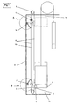
- the elevator system shown requires a temporary shelter space at both ends of the car lane (4b, 4a).
- a cabin (1) is provided with a double-acting cabin-catching device (5).
- the cabin-catching device (5) is actuated via an associated operating unit catching device (6) and a speed limiting cable (10) in the event of an overspeed of the car (1) by a speed limiter (9).
- the actuated cabin-catching devices (5) bring the cabin (1) to a standstill.
- a stop (13) is fastened in the speed limiter cable (10).
- a first barrier (14) is fixed at the top and a second barrier (17) at the bottom.
- Upper and lower forks (15, 18) are brought into a stop position (S) or an open position (O) by an actuating element (16, 19).
- the stop (13) unhindered at the locks (14,17) past.
- the cabin (1) can reach the end positions provided according to the elevator installation.
- the stop (13) is limited in its travel through the locks (14,17).
- the stop (13) fastened to the speed limiter cable (10) stops the speed limiter cable (10) when one of the locks (14 or 17) is reached, which thus actuates the cabin safety device (5) and forcibly stops the cabin (1).
- the car (1) can no longer reach the end positions.
- the required temporary shelters (4b, 4a) at the lower and upper end of the car lane are guaranteed.
- the illustrated solution provides a cost effective way to ensure the required temporary shelter. It is easy to install and the function can be visually checked by the maintenance personnel at any time, since the position of the barriers (14, 17) is visually easy to see.
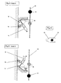
- the barrier (14,17) is also, as shown in Fig. II and III, designed such that it can apply the required operating force only in one direction of travel, and does not obstruct the movement in the opposite direction. This allows that no special monitoring unit must observe the location of the car (1) when extending the barrier (14, 17). If, for example, the car is in the lowermost stop when the lock (14) is being extended, that is to say within the space (4b) to be protected, the lock (14) can nevertheless be extended. There is no danger as access to the shaft pit is blocked by the cabin (1) at the bottom. However, now the car (1) with low speed, to outside the Shelter (4b), without being prevented by the lock (14).
- the stop (13) together with a connection point (7) to the operating unit safety gear (6) form an assembly. This allows a better placement possibility of the locks in individual cases (14, 17).
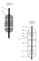
- the stopper (13) is executed as shown in Fig. V by way of example in the form of a cylinder with rounded end portions. It is clamped in the area around (10a) of the speed limiter cable (10) on the speed limiter cable (10) or together with the connection point (7) forms an assembly.
- Fig. V shown embodiment without special elastic property, is primarily suitable for cabin-catching devices (5) with blocking function. This design is particularly inexpensive to implement and easy to install.
- the stop block (20) is clamped in the counter area (10a) of the speed limiter cable on the speed limiter cable (10) or together with the connection point (7) forms an assembly.
- the stop ends (22) are guided in a guide (23).
- This embodiment allows thegraphybeskyrseil (10), after actuation of the car catching device (5), a further movement corresponding to the stop path of the car (1), wherein the stop end, after the provision of the cabin (1) in the shortened shaft area, again in the Reset initial position.
- This embodiment is preferably suitable for cabin-catching devices (5) with a braking characteristic (brake-catching devices).
- the barrier (14, 17) is preferably in the form of a fork (15) as shown in Fig. IV .
- the fork (15) encloses, in the stop position (S) of the barrier (14, 17), the speed limiter rope (10) on three sides. As a result, the speed limiter cable (10) is essentially guided. This design is inexpensive and easy to perform.
- the fork (15) of the barrier (17, 14) is supported, for example, as shown in Fig. III by means of an elastic element on the wall support, thegraphybegrenzerseil (10) is also a further movement corresponding to the stop path of the car (1).
- the proposed design allows the fork (15) to push back to the desired position as soon as the cab (1) is returned to the shortened shaft area.
- the position of the barrier (14, 17) as shown in FIGS. II and III is controlled by a respective solenoid (16). This allows a safe and cost-effective operation of the locks (14, 17) according to the control request.
- one barrier is used to limit the carriageway in both end zones.
- the barrier installed in the upper shaft area (14) for setting up a temporary shelter below and the corresponding need is optionally in the lower shaft area, the lock (17) used to set up a temporary shelter above.
- the assignment is changed accordingly.
- the optional use of the barriers (14, 17) allows a needs-based, and thus cost-effective solution for setting up a temporary shelter.
- the parts required for setting up a temporary shelter such as stop (13), one or more locks (14,17) and switching elements can be easily mounted in the elevator system. The function is easy to see.
- the invention is suitable for existing, but also for new plants.
- the stop position (S) of the stops (14, 17) is monitored electrically (not shown in the figures). In the stop position (S) thus a normal drive is prevented. Upon actuation of the car-catching device (5), a safety contact of the car-catching device (5) is inevitably opened, resulting in an electrical cut-off of the drive leads.
- a proposed evacuation device allows a return movement of the cabin from the crossing zone in the shortened shaft area. This allows a quick evacuation of trapped persons.
- the locks (14, 17) are extended in the manual opening of a shaft closure, for example, to perform maintenance work within the shaft.
- a provision of the locks (14, 17) can only be made from outside the shaft by an authorized person. The authorization is checked by known elements such as keys, code entry or similar procedures. Alternatively, the provision can be disabled by additional systems such as presence detectors in the shaft space.
- the barriers (14, 17) can additionally be monitored by monitoring the intermediate barriers.
- the intermediate barriers are, for example, grids which are installed between two adjacent car lanes and which are usually provided with passage openings.
- the elevator expert can arbitrarily change the set shapes and arrangements.
- the shown swivel shape of the barriers can also be replaced by a shock shape or the circuit of the lock can be used in addition to solenoids and mechanical elements, such as. Bowden cables, or electromechanical elements such as. Actuators, other electromagnets, or other elements.
Landscapes
- Maintenance And Inspection Apparatuses For Elevators (AREA)
- Cage And Drive Apparatuses For Elevators (AREA)
- Lift-Guide Devices, And Elevator Ropes And Cables (AREA)
- Automobile Manufacture Line, Endless Track Vehicle, Trailer (AREA)
- Braking Arrangements (AREA)
- Vending Machines For Individual Products (AREA)
- Escalators And Moving Walkways (AREA)
- Types And Forms Of Lifts (AREA)
- Forklifts And Lifting Vehicles (AREA)
Priority Applications (3)
| Application Number | Priority Date | Filing Date | Title |
|---|---|---|---|
| PL04010417T PL1475342T3 (pl) | 2003-05-07 | 2004-05-03 | Urządzenie do stworzenia tymczasowej strefy ochronnej w windach |
| EP04010417A EP1475342B1 (de) | 2003-05-07 | 2004-05-03 | Vorrichtung zur Einrichtung eines temporären Schutzraumes für Aufzüge |
| ES04010417T ES2303919T3 (es) | 2003-05-07 | 2004-05-03 | Sistema para la creacion de un espacio temporal de proteccion para ascensores. |
Applications Claiming Priority (3)
| Application Number | Priority Date | Filing Date | Title |
|---|---|---|---|
| EP03405320 | 2003-05-07 | ||
| EP03405320 | 2003-05-07 | ||
| EP04010417A EP1475342B1 (de) | 2003-05-07 | 2004-05-03 | Vorrichtung zur Einrichtung eines temporären Schutzraumes für Aufzüge |
Publications (2)
| Publication Number | Publication Date |
|---|---|
| EP1475342A1 EP1475342A1 (de) | 2004-11-10 |
| EP1475342B1 true EP1475342B1 (de) | 2008-03-26 |
Family
ID=33396085
Family Applications (1)
| Application Number | Title | Priority Date | Filing Date |
|---|---|---|---|
| EP04010417A Expired - Lifetime EP1475342B1 (de) | 2003-05-07 | 2004-05-03 | Vorrichtung zur Einrichtung eines temporären Schutzraumes für Aufzüge |
Country Status (12)
| Country | Link |
|---|---|
| US (1) | US7278517B2 (pl) |
| EP (1) | EP1475342B1 (pl) |
| JP (1) | JP4673574B2 (pl) |
| CN (1) | CN1326762C (pl) |
| AT (1) | ATE390378T1 (pl) |
| AU (1) | AU2004201959B2 (pl) |
| CA (1) | CA2466406C (pl) |
| DE (1) | DE502004006632D1 (pl) |
| ES (1) | ES2303919T3 (pl) |
| NO (1) | NO329635B1 (pl) |
| PL (1) | PL1475342T3 (pl) |
| PT (1) | PT1475342E (pl) |
Families Citing this family (20)
| Publication number | Priority date | Publication date | Assignee | Title |
|---|---|---|---|---|
| FI118079B (fi) * | 2004-03-26 | 2007-06-29 | Kone Corp | Hissi, menetelmä hissin liikkeen estämiseksi ja/tai pysäyttämiseksi ja hissikorin liikkeen estävän ja/tai pysäyttävän laitteen käyttö hississä |
| WO2006062503A1 (en) * | 2004-12-03 | 2006-06-15 | Otis Elevator Company | Safety device for use in an elevator system |
| US8136637B2 (en) * | 2006-06-30 | 2012-03-20 | Otis Elevator Company | Safety device for securing minimum spaces at the top or bottom of an elevator shaft being inspected, and elevator having such safety devices |
| WO2008004022A1 (en) * | 2006-06-30 | 2008-01-10 | Otis Elevator Company | Elevator having a shallow pit and/or a low overhead |
| FI125141B (fi) * | 2007-01-03 | 2015-06-15 | Kone Corp | Hissin turvalaite |
| FI20070486L (fi) * | 2007-01-03 | 2008-07-04 | Kone Corp | Hissin turvajärjestely |
| FI120788B (fi) * | 2008-06-30 | 2010-03-15 | Kone Corp | Hissijärjestely |
| FI121423B (fi) * | 2009-04-23 | 2010-11-15 | Kone Corp | Hissin turvajärjestely |
| WO2011030325A1 (en) | 2009-09-13 | 2011-03-17 | Yoram Madar | Safety devices for elevators with reduced clearances |
| FI122064B (fi) * | 2009-11-13 | 2011-08-15 | Kone Corp | Hissi ja menetelmä turvatilan muodostamiseksi |
| DE102010030436A1 (de) * | 2010-06-23 | 2011-12-29 | Thyssenkrupp Elevator Ag | Aufzuganlage |
| FR2977881B1 (fr) * | 2011-07-13 | 2015-08-21 | Arnoult Patrice | Dispositif de blocage de cabine d'ascenseur dans une gaine a une distance determinee du plafond ou du sol de la gaine |
| WO2014040861A1 (de) * | 2012-09-14 | 2014-03-20 | Inventio Ag | Betätigungselement für eine fangvorrichtung |
| ES2568907T3 (es) * | 2012-10-30 | 2016-05-05 | Kone Corporation | Un ascensor y un método |
| FI125118B (fi) * | 2013-01-07 | 2015-06-15 | Kone Corp | Hissi |
| FI125176B (fi) * | 2014-01-21 | 2015-06-30 | Kone Corp | Turvalaitteistojärjestelyllä varustettu hissi |
| CN107074489B (zh) | 2014-09-22 | 2019-03-19 | 三菱电机株式会社 | 电梯装置 |
| EP3153446B1 (en) | 2015-10-09 | 2018-10-03 | KONE Corporation | Elevator safety device |
| US10457522B2 (en) * | 2016-06-30 | 2019-10-29 | Otis Elevator Company | Limit switch system including first limit device and second limit device |
| EP3498652A1 (en) * | 2017-12-18 | 2019-06-19 | Aip Aps | Methods and systems for transferring weight of an elevator cabin |
Family Cites Families (12)
| Publication number | Priority date | Publication date | Assignee | Title |
|---|---|---|---|---|
| US3211258A (en) * | 1960-10-05 | 1965-10-12 | Dickmann Giulio | Intermittently actuated switch selector for an elevator control |
| JPS50160952A (pl) * | 1974-06-19 | 1975-12-26 | ||
| FI92812C (fi) * | 1992-07-07 | 1995-01-10 | Kone Oy | Turvalaitejärjestely |
| US5613576A (en) * | 1995-05-18 | 1997-03-25 | Inventio Ag | Apparatus for preventing drift of an elevator car stopped at a floor |
| US5806633A (en) * | 1995-12-22 | 1998-09-15 | Macuga; Henry J. | Elevator safety system incorporating false pit |
| JPH1045347A (ja) * | 1996-07-31 | 1998-02-17 | Otis Elevator Co | エレベーターの非常止め装置 |
| JP3408938B2 (ja) * | 1996-12-26 | 2003-05-19 | 株式会社日立ビルシステム | 工事用エレベータ |
| JPH10338433A (ja) * | 1997-06-10 | 1998-12-22 | Hitachi Building Syst Co Ltd | ガバナトリップ試験用落下物捕獲装置 |
| ATE412604T1 (de) * | 2000-01-19 | 2008-11-15 | Thyssenkrupp Aufzugswerke Gmbh | Aufzuganlage mit verringerter schachtgrubentiefe |
| KR200221450Y1 (ko) * | 2000-10-21 | 2001-04-16 | 편준기 | 엘리베이터용 로프 제동장치 |
| SE521817C2 (sv) * | 2000-11-02 | 2003-12-09 | Alimak Ab | Säkerhetsarrangemang vid hiss |
| TW593117B (en) * | 2000-12-07 | 2004-06-21 | Inventio Ag | Safety brake and method for unlocking a safety brake |
-
2004
- 2004-04-23 JP JP2004128317A patent/JP4673574B2/ja not_active Expired - Fee Related
- 2004-04-28 CN CNB2004100386164A patent/CN1326762C/zh not_active Expired - Fee Related
- 2004-05-03 PT PT04010417T patent/PT1475342E/pt unknown
- 2004-05-03 ES ES04010417T patent/ES2303919T3/es not_active Expired - Lifetime
- 2004-05-03 PL PL04010417T patent/PL1475342T3/pl unknown
- 2004-05-03 AT AT04010417T patent/ATE390378T1/de active
- 2004-05-03 EP EP04010417A patent/EP1475342B1/de not_active Expired - Lifetime
- 2004-05-03 DE DE502004006632T patent/DE502004006632D1/de not_active Expired - Lifetime
- 2004-05-04 US US10/838,850 patent/US7278517B2/en not_active Expired - Fee Related
- 2004-05-05 AU AU2004201959A patent/AU2004201959B2/en not_active Ceased
- 2004-05-05 CA CA2466406A patent/CA2466406C/en not_active Expired - Fee Related
- 2004-05-06 NO NO20041861A patent/NO329635B1/no not_active IP Right Cessation
Also Published As
| Publication number | Publication date |
|---|---|
| CN1550442A (zh) | 2004-12-01 |
| US7278517B2 (en) | 2007-10-09 |
| HK1071120A1 (zh) | 2005-07-08 |
| EP1475342A1 (de) | 2004-11-10 |
| CN1326762C (zh) | 2007-07-18 |
| NO329635B1 (no) | 2010-11-22 |
| NO20041861L (no) | 2004-11-08 |
| DE502004006632D1 (de) | 2008-05-08 |
| US20040222046A1 (en) | 2004-11-11 |
| JP2004352503A (ja) | 2004-12-16 |
| CA2466406A1 (en) | 2004-11-07 |
| AU2004201959B2 (en) | 2009-04-02 |
| CA2466406C (en) | 2011-04-19 |
| ES2303919T3 (es) | 2008-09-01 |
| JP4673574B2 (ja) | 2011-04-20 |
| PT1475342E (pt) | 2008-06-23 |
| AU2004201959A1 (en) | 2004-11-25 |
| PL1475342T3 (pl) | 2008-09-30 |
| ATE390378T1 (de) | 2008-04-15 |
Similar Documents
| Publication | Publication Date | Title |
|---|---|---|
| EP1475342B1 (de) | Vorrichtung zur Einrichtung eines temporären Schutzraumes für Aufzüge | |
| EP2516307B1 (de) | Schachtzugangsfreigabevorrichtung einer aufzugsanlage | |
| EP0543154B1 (de) | Vorrichtung zum Auslösen von Sicherheitseinrichtungen | |
| EP1213247B1 (de) | Vorrichtung und Verfahren zum Entsperren einer Fangvorrichtung | |
| DE10108772A1 (de) | Aufzugssicherheitseinrichtung | |
| EP3003944B1 (de) | Aufzugsschacht mit verkleinerter schachtgrube bzw. verkleinertem schachtkopf | |
| DE102012016336A1 (de) | Geschwindigkeitsbegrenzer für ein Aufzugsystem | |
| WO2016091777A1 (de) | Entriegelungsvorrichtung, aufzugsanlage mit einer entriegelungsvorrichtung und ein verfahren zum betätigen einer entriegelungsvorrichtung | |
| EP3538468B1 (de) | Seilbremse, aufzugskabine und aufzugsanlage | |
| EP2370333A1 (de) | Aufzugsanlage mit einer sicherheitseinrichtung | |
| EP0151427B1 (de) | Federüberwachungsgerät | |
| EP4069934B1 (de) | Personenvereinzelungsanlage | |
| EP1562849B1 (de) | Aufzugssteuerung eingebaut im türpfosten | |
| EP0926093B1 (de) | Aufzug, insbesondere Treibscheibenaufzug | |
| DE102008038409B4 (de) | Vorrichtung zur Sicherung von Schachtzugängen von Aufzugsanlagen | |
| EP3748112A1 (de) | Absturzsicherung für ein hubtor, insbesondere maschinenschutzhubtor | |
| DE102019212726A1 (de) | Aufzugsanlage die einen Fahrkorb abhängig von einem Schließzustandssignal und einer Position des Fahrkorbs in einen Sicherheitsbetriebszustand überführt | |
| EP1602615B1 (de) | Sicherheitseinrichtung zum Festsetzen einer Aufzugskabine | |
| EP3927641B1 (de) | Auslösesystem für eine fangvorrichtung, aufzugsanlage und verfahren zum betreiben einer aufzugsanlage | |
| DE2833353A1 (de) | Fanganlage zum gezielten und gewaltsamen abbremsen und einfangen von fahrzeugen | |
| WO1999040015A1 (de) | Sicherheitseinrichtung für bauaufzug | |
| DE102011001449A1 (de) | Sicherheitsfangvorrichtung für eine Aufzugsanlage sowie Verfahren zur Sicherung einer schienengeführten Aufzugskabine einer Aufzugsanlage | |
| DE3504264A1 (de) | Vorrichtung zum begrenzen der abwaertsfahrt eines aufzuges | |
| EP1439144A2 (de) | Bremsvorrichtung für eine Aufzuganlage | |
| DE10065099A1 (de) | Schutzvorrichtung zur Erzeugung eines Schutzraumes |
Legal Events
| Date | Code | Title | Description |
|---|---|---|---|
| PUAI | Public reference made under article 153(3) epc to a published international application that has entered the european phase |
Free format text: ORIGINAL CODE: 0009012 |
|
| AK | Designated contracting states |
Kind code of ref document: A1 Designated state(s): AT BE BG CH CY CZ DE DK EE ES FI FR GB GR HU IE IT LI LU MC NL PL PT RO SE SI SK TR |
|
| AX | Request for extension of the european patent |
Extension state: AL HR LT LV MK |
|
| 17P | Request for examination filed |
Effective date: 20050426 |
|
| REG | Reference to a national code |
Ref country code: HK Ref legal event code: DE Ref document number: 1071120 Country of ref document: HK |
|
| AKX | Designation fees paid |
Designated state(s): AT BE BG CH CY CZ DE DK EE ES FI FR GB GR HU IE IT LI LU MC NL PL PT RO SE SI SK TR |
|
| GRAP | Despatch of communication of intention to grant a patent |
Free format text: ORIGINAL CODE: EPIDOSNIGR1 |
|
| GRAS | Grant fee paid |
Free format text: ORIGINAL CODE: EPIDOSNIGR3 |
|
| GRAA | (expected) grant |
Free format text: ORIGINAL CODE: 0009210 |
|
| AK | Designated contracting states |
Kind code of ref document: B1 Designated state(s): AT BE BG CH CY CZ DE DK EE ES FI FR GB GR HU IE IT LI LU MC NL PL PT RO SE SI SK TR |
|
| REG | Reference to a national code |
Ref country code: GB Ref legal event code: FG4D Free format text: NOT ENGLISH |
|
| REG | Reference to a national code |
Ref country code: IE Ref legal event code: FG4D Free format text: LANGUAGE OF EP DOCUMENT: GERMAN Ref country code: CH Ref legal event code: EP |
|
| REF | Corresponds to: |
Ref document number: 502004006632 Country of ref document: DE Date of ref document: 20080508 Kind code of ref document: P |
|
| REG | Reference to a national code |
Ref country code: GR Ref legal event code: EP Ref document number: 20080401401 Country of ref document: GR |
|
| REG | Reference to a national code |
Ref country code: PT Ref legal event code: SC4A Free format text: AVAILABILITY OF NATIONAL TRANSLATION Effective date: 20080609 Ref country code: RO Ref legal event code: EPE |
|
| REG | Reference to a national code |
Ref country code: SE Ref legal event code: TRGR |
|
| REG | Reference to a national code |
Ref country code: ES Ref legal event code: FG2A Ref document number: 2303919 Country of ref document: ES Kind code of ref document: T3 |
|
| PG25 | Lapsed in a contracting state [announced via postgrant information from national office to epo] |
Ref country code: SI Free format text: LAPSE BECAUSE OF FAILURE TO SUBMIT A TRANSLATION OF THE DESCRIPTION OR TO PAY THE FEE WITHIN THE PRESCRIBED TIME-LIMIT Effective date: 20080326 |
|
| REG | Reference to a national code |
Ref country code: PL Ref legal event code: T3 |
|
| ET | Fr: translation filed | ||
| REG | Reference to a national code |
Ref country code: IE Ref legal event code: FD4D |
|
| PG25 | Lapsed in a contracting state [announced via postgrant information from national office to epo] |
Ref country code: SK Free format text: LAPSE BECAUSE OF FAILURE TO SUBMIT A TRANSLATION OF THE DESCRIPTION OR TO PAY THE FEE WITHIN THE PRESCRIBED TIME-LIMIT Effective date: 20080326 |
|
| REG | Reference to a national code |
Ref country code: HK Ref legal event code: GR Ref document number: 1071120 Country of ref document: HK |
|
| PG25 | Lapsed in a contracting state [announced via postgrant information from national office to epo] |
Ref country code: MC Free format text: LAPSE BECAUSE OF NON-PAYMENT OF DUE FEES Effective date: 20080531 |
|
| PG25 | Lapsed in a contracting state [announced via postgrant information from national office to epo] |
Ref country code: IE Free format text: LAPSE BECAUSE OF FAILURE TO SUBMIT A TRANSLATION OF THE DESCRIPTION OR TO PAY THE FEE WITHIN THE PRESCRIBED TIME-LIMIT Effective date: 20080326 Ref country code: DK Free format text: LAPSE BECAUSE OF FAILURE TO SUBMIT A TRANSLATION OF THE DESCRIPTION OR TO PAY THE FEE WITHIN THE PRESCRIBED TIME-LIMIT Effective date: 20080326 |
|
| PLBE | No opposition filed within time limit |
Free format text: ORIGINAL CODE: 0009261 |
|
| STAA | Information on the status of an ep patent application or granted ep patent |
Free format text: STATUS: NO OPPOSITION FILED WITHIN TIME LIMIT |
|
| 26N | No opposition filed |
Effective date: 20081230 |
|
| PG25 | Lapsed in a contracting state [announced via postgrant information from national office to epo] |
Ref country code: BG Free format text: LAPSE BECAUSE OF FAILURE TO SUBMIT A TRANSLATION OF THE DESCRIPTION OR TO PAY THE FEE WITHIN THE PRESCRIBED TIME-LIMIT Effective date: 20080626 |
|
| PG25 | Lapsed in a contracting state [announced via postgrant information from national office to epo] |
Ref country code: CY Free format text: LAPSE BECAUSE OF FAILURE TO SUBMIT A TRANSLATION OF THE DESCRIPTION OR TO PAY THE FEE WITHIN THE PRESCRIBED TIME-LIMIT Effective date: 20080326 |
|
| PG25 | Lapsed in a contracting state [announced via postgrant information from national office to epo] |
Ref country code: LU Free format text: LAPSE BECAUSE OF NON-PAYMENT OF DUE FEES Effective date: 20080503 Ref country code: HU Free format text: LAPSE BECAUSE OF FAILURE TO SUBMIT A TRANSLATION OF THE DESCRIPTION OR TO PAY THE FEE WITHIN THE PRESCRIBED TIME-LIMIT Effective date: 20080927 |
|
| PGFP | Annual fee paid to national office [announced via postgrant information from national office to epo] |
Ref country code: CZ Payment date: 20120426 Year of fee payment: 9 Ref country code: EE Payment date: 20120514 Year of fee payment: 9 |
|
| PGFP | Annual fee paid to national office [announced via postgrant information from national office to epo] |
Ref country code: GR Payment date: 20120530 Year of fee payment: 9 Ref country code: RO Payment date: 20120502 Year of fee payment: 9 |
|
| PG25 | Lapsed in a contracting state [announced via postgrant information from national office to epo] |
Ref country code: CZ Free format text: LAPSE BECAUSE OF NON-PAYMENT OF DUE FEES Effective date: 20130503 Ref country code: EE Free format text: LAPSE BECAUSE OF NON-PAYMENT OF DUE FEES Effective date: 20130531 |
|
| REG | Reference to a national code |
Ref country code: GR Ref legal event code: ML Ref document number: 20080401401 Country of ref document: GR Effective date: 20131204 |
|
| REG | Reference to a national code |
Ref country code: EE Ref legal event code: MM4A Ref document number: E002125 Country of ref document: EE Effective date: 20130531 |
|
| PG25 | Lapsed in a contracting state [announced via postgrant information from national office to epo] |
Ref country code: GR Free format text: LAPSE BECAUSE OF NON-PAYMENT OF DUE FEES Effective date: 20131204 Ref country code: RO Free format text: LAPSE BECAUSE OF NON-PAYMENT OF DUE FEES Effective date: 20130503 |
|
| REG | Reference to a national code |
Ref country code: FR Ref legal event code: PLFP Year of fee payment: 13 |
|
| REG | Reference to a national code |
Ref country code: FR Ref legal event code: PLFP Year of fee payment: 14 |
|
| PGFP | Annual fee paid to national office [announced via postgrant information from national office to epo] |
Ref country code: NL Payment date: 20170519 Year of fee payment: 14 |
|
| PGFP | Annual fee paid to national office [announced via postgrant information from national office to epo] |
Ref country code: FR Payment date: 20170523 Year of fee payment: 14 Ref country code: GB Payment date: 20170519 Year of fee payment: 14 Ref country code: CH Payment date: 20170519 Year of fee payment: 14 Ref country code: DE Payment date: 20170523 Year of fee payment: 14 |
|
| PGFP | Annual fee paid to national office [announced via postgrant information from national office to epo] |
Ref country code: IT Payment date: 20170526 Year of fee payment: 14 Ref country code: BE Payment date: 20170519 Year of fee payment: 14 Ref country code: ES Payment date: 20170628 Year of fee payment: 14 Ref country code: SE Payment date: 20170519 Year of fee payment: 14 Ref country code: FI Payment date: 20170511 Year of fee payment: 14 Ref country code: AT Payment date: 20170522 Year of fee payment: 14 Ref country code: PT Payment date: 20170502 Year of fee payment: 14 |
|
| PGFP | Annual fee paid to national office [announced via postgrant information from national office to epo] |
Ref country code: TR Payment date: 20170425 Year of fee payment: 14 |
|
| PGFP | Annual fee paid to national office [announced via postgrant information from national office to epo] |
Ref country code: PL Payment date: 20170502 Year of fee payment: 14 |
|
| REG | Reference to a national code |
Ref country code: DE Ref legal event code: R119 Ref document number: 502004006632 Country of ref document: DE |
|
| REG | Reference to a national code |
Ref country code: CH Ref legal event code: PL |
|
| REG | Reference to a national code |
Ref country code: SE Ref legal event code: EUG Ref country code: NL Ref legal event code: MM Effective date: 20180601 |
|
| REG | Reference to a national code |
Ref country code: AT Ref legal event code: MM01 Ref document number: 390378 Country of ref document: AT Kind code of ref document: T Effective date: 20180503 |
|
| GBPC | Gb: european patent ceased through non-payment of renewal fee |
Effective date: 20180503 |
|
| REG | Reference to a national code |
Ref country code: BE Ref legal event code: MM Effective date: 20180531 |
|
| PG25 | Lapsed in a contracting state [announced via postgrant information from national office to epo] |
Ref country code: FI Free format text: LAPSE BECAUSE OF NON-PAYMENT OF DUE FEES Effective date: 20180503 Ref country code: AT Free format text: LAPSE BECAUSE OF NON-PAYMENT OF DUE FEES Effective date: 20180503 Ref country code: SE Free format text: LAPSE BECAUSE OF NON-PAYMENT OF DUE FEES Effective date: 20180504 Ref country code: PT Free format text: LAPSE BECAUSE OF NON-PAYMENT OF DUE FEES Effective date: 20181105 |
|
| PG25 | Lapsed in a contracting state [announced via postgrant information from national office to epo] |
Ref country code: LI Free format text: LAPSE BECAUSE OF NON-PAYMENT OF DUE FEES Effective date: 20180531 Ref country code: CH Free format text: LAPSE BECAUSE OF NON-PAYMENT OF DUE FEES Effective date: 20180531 |
|
| PG25 | Lapsed in a contracting state [announced via postgrant information from national office to epo] |
Ref country code: IT Free format text: LAPSE BECAUSE OF NON-PAYMENT OF DUE FEES Effective date: 20180503 Ref country code: NL Free format text: LAPSE BECAUSE OF NON-PAYMENT OF DUE FEES Effective date: 20180601 Ref country code: DE Free format text: LAPSE BECAUSE OF NON-PAYMENT OF DUE FEES Effective date: 20181201 Ref country code: GB Free format text: LAPSE BECAUSE OF NON-PAYMENT OF DUE FEES Effective date: 20180503 Ref country code: FR Free format text: LAPSE BECAUSE OF NON-PAYMENT OF DUE FEES Effective date: 20180531 |
|
| PG25 | Lapsed in a contracting state [announced via postgrant information from national office to epo] |
Ref country code: BE Free format text: LAPSE BECAUSE OF NON-PAYMENT OF DUE FEES Effective date: 20180531 |
|
| REG | Reference to a national code |
Ref country code: ES Ref legal event code: FD2A Effective date: 20190913 |
|
| PG25 | Lapsed in a contracting state [announced via postgrant information from national office to epo] |
Ref country code: ES Free format text: LAPSE BECAUSE OF NON-PAYMENT OF DUE FEES Effective date: 20180504 |
|
| PG25 | Lapsed in a contracting state [announced via postgrant information from national office to epo] |
Ref country code: PL Free format text: LAPSE BECAUSE OF NON-PAYMENT OF DUE FEES Effective date: 20180503 |
|
| PG25 | Lapsed in a contracting state [announced via postgrant information from national office to epo] |
Ref country code: TR Free format text: LAPSE BECAUSE OF NON-PAYMENT OF DUE FEES Effective date: 20180503 |