EP1473200B1 - Gassack-Modul - Google Patents
Gassack-Modul Download PDFInfo
- Publication number
- EP1473200B1 EP1473200B1 EP04009611A EP04009611A EP1473200B1 EP 1473200 B1 EP1473200 B1 EP 1473200B1 EP 04009611 A EP04009611 A EP 04009611A EP 04009611 A EP04009611 A EP 04009611A EP 1473200 B1 EP1473200 B1 EP 1473200B1
- Authority
- EP
- European Patent Office
- Prior art keywords
- housing
- gas generator
- gas
- gas bag
- igniter
- Prior art date
- Legal status (The legal status is an assumption and is not a legal conclusion. Google has not performed a legal analysis and makes no representation as to the accuracy of the status listed.)
- Expired - Lifetime
Links
- 230000004913 activation Effects 0.000 description 1
- 230000001419 dependent effect Effects 0.000 description 1
- 239000002184 metal Substances 0.000 description 1
Images

Classifications
-
- B—PERFORMING OPERATIONS; TRANSPORTING
- B60—VEHICLES IN GENERAL
- B60R—VEHICLES, VEHICLE FITTINGS, OR VEHICLE PARTS, NOT OTHERWISE PROVIDED FOR
- B60R21/00—Arrangements or fittings on vehicles for protecting or preventing injuries to occupants or pedestrians in case of accidents or other traffic risks
- B60R21/02—Occupant safety arrangements or fittings, e.g. crash pads
- B60R21/16—Inflatable occupant restraints or confinements designed to inflate upon impact or impending impact, e.g. air bags
- B60R21/20—Arrangements for storing inflatable members in their non-use or deflated condition; Arrangement or mounting of air bag modules or components
- B60R21/217—Inflation fluid source retainers, e.g. reaction canisters; Connection of bags, covers, diffusers or inflation fluid sources therewith or together
- B60R21/2171—Inflation fluid source retainers, e.g. reaction canisters; Connection of bags, covers, diffusers or inflation fluid sources therewith or together specially adapted for elongated cylindrical or bottle-like inflators with a symmetry axis perpendicular to the main direction of bag deployment, e.g. extruded reaction canisters
-
- B—PERFORMING OPERATIONS; TRANSPORTING
- B60—VEHICLES IN GENERAL
- B60R—VEHICLES, VEHICLE FITTINGS, OR VEHICLE PARTS, NOT OTHERWISE PROVIDED FOR
- B60R21/00—Arrangements or fittings on vehicles for protecting or preventing injuries to occupants or pedestrians in case of accidents or other traffic risks
- B60R21/02—Occupant safety arrangements or fittings, e.g. crash pads
- B60R21/16—Inflatable occupant restraints or confinements designed to inflate upon impact or impending impact, e.g. air bags
- B60R21/26—Inflatable occupant restraints or confinements designed to inflate upon impact or impending impact, e.g. air bags characterised by the inflation fluid source or means to control inflation fluid flow
- B60R21/264—Inflatable occupant restraints or confinements designed to inflate upon impact or impending impact, e.g. air bags characterised by the inflation fluid source or means to control inflation fluid flow using instantaneous generation of gas, e.g. pyrotechnic
- B60R21/2644—Inflatable occupant restraints or confinements designed to inflate upon impact or impending impact, e.g. air bags characterised by the inflation fluid source or means to control inflation fluid flow using instantaneous generation of gas, e.g. pyrotechnic using only solid reacting substances, e.g. pellets, powder
-
- B—PERFORMING OPERATIONS; TRANSPORTING
- B60—VEHICLES IN GENERAL
- B60R—VEHICLES, VEHICLE FITTINGS, OR VEHICLE PARTS, NOT OTHERWISE PROVIDED FOR
- B60R21/00—Arrangements or fittings on vehicles for protecting or preventing injuries to occupants or pedestrians in case of accidents or other traffic risks
- B60R21/02—Occupant safety arrangements or fittings, e.g. crash pads
- B60R21/16—Inflatable occupant restraints or confinements designed to inflate upon impact or impending impact, e.g. air bags
- B60R21/26—Inflatable occupant restraints or confinements designed to inflate upon impact or impending impact, e.g. air bags characterised by the inflation fluid source or means to control inflation fluid flow
- B60R21/263—Inflatable occupant restraints or confinements designed to inflate upon impact or impending impact, e.g. air bags characterised by the inflation fluid source or means to control inflation fluid flow using a variable source, e.g. plural stage or controlled output
- B60R2021/2633—Inflatable occupant restraints or confinements designed to inflate upon impact or impending impact, e.g. air bags characterised by the inflation fluid source or means to control inflation fluid flow using a variable source, e.g. plural stage or controlled output with a plurality of inflation levels
-
- B—PERFORMING OPERATIONS; TRANSPORTING
- B60—VEHICLES IN GENERAL
- B60R—VEHICLES, VEHICLE FITTINGS, OR VEHICLE PARTS, NOT OTHERWISE PROVIDED FOR
- B60R21/00—Arrangements or fittings on vehicles for protecting or preventing injuries to occupants or pedestrians in case of accidents or other traffic risks
- B60R21/02—Occupant safety arrangements or fittings, e.g. crash pads
- B60R21/16—Inflatable occupant restraints or confinements designed to inflate upon impact or impending impact, e.g. air bags
- B60R21/26—Inflatable occupant restraints or confinements designed to inflate upon impact or impending impact, e.g. air bags characterised by the inflation fluid source or means to control inflation fluid flow
- B60R21/264—Inflatable occupant restraints or confinements designed to inflate upon impact or impending impact, e.g. air bags characterised by the inflation fluid source or means to control inflation fluid flow using instantaneous generation of gas, e.g. pyrotechnic
- B60R21/2644—Inflatable occupant restraints or confinements designed to inflate upon impact or impending impact, e.g. air bags characterised by the inflation fluid source or means to control inflation fluid flow using instantaneous generation of gas, e.g. pyrotechnic using only solid reacting substances, e.g. pellets, powder
- B60R2021/2648—Inflatable occupant restraints or confinements designed to inflate upon impact or impending impact, e.g. air bags characterised by the inflation fluid source or means to control inflation fluid flow using instantaneous generation of gas, e.g. pyrotechnic using only solid reacting substances, e.g. pellets, powder comprising a plurality of combustion chambers or sub-chambers
Definitions
- the invention relates to a gas bag module and in particular an airbag module for a passenger of a vehicle.
- Conventional gas bag modules have a generally cylindrical gas generator, at least one igniter and a housing to which the gas generator is attached. Such a gas bag module should require minimal space and have a low weight. In addition, it should have a simple structure to be manufactured at low cost. Finally, low leakage losses during inflation of the gas bag should occur in order to achieve the highest possible efficiency.
- the object of the invention is to provide a cost-effective airbag module of the type mentioned, which meets the requirements mentioned.
- Document EP 1396396 A1 is a document according to Article 54 (3) EPC and discloses a gas bag module having a cylindrical gas generator, at least one igniter and a holding plate to which the gas generator is attached, the igniter extending radially out of the gas generator and on the holding plate is fixed, and wherein a gas bag is provided, which is clamped between the holding plate and the gas generator.
- the invention provides an airbag module with a generally cylindrical gas generator, at least one igniter and a housing to which the gas generator is attached, wherein the igniter extends radially out of the gas generator and secured to the housing, wherein an airbag is provided which is clamped between the housing and the gas generator, and wherein the housing has a trough-shaped receiving portion for the gas generator.
- the invention is based on the idea of using the igniter to attach the gas generator to the housing. In this way, on the one hand results in a simple structure, since it can be dispensed with the otherwise conventional mounting plates, etc .; for fixing the gas generator in the housing an already existing component is used.
- To attach the igniter to the housing of the detonator may be provided with a holding geometry, by means of which it is locked to the housing, so that the gas generator is firmly connected to the housing.
- a holding geometry in particular an external thread can be used, onto which a nut is screwed, which lies outside of the housing and in this way connects the gas generator firmly to the housing.
- a groove is used as a holding geometry, in which a retaining ring is used.
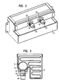
- FIGS. 1 to 3 show an airbag module which has a housing 10.
- the housing 10 serves to receive a folded gas bag 12 and a gas generator 14.
- the gas generator which is designed here as a cylindrical tube gas generator, can provide after activation a compressed gas, by means of which the gas bag 12 can be deployed in a conventional manner.
- the housing 10 may be made of sheet metal and serves as a receptacle for the other components of the gas bag module and on the other hand allows the attachment of the gas bag module in a vehicle.
- the gas generator 14 is provided with two detonators 16, which are arranged radially with respect to the central axis of the gas generator 14. Each of the detonators is associated with its own gas-generating charge;
- the gas generator is a 2-stage gas generator. However, it is also possible to use a gas generator with more than 2 stages.
- the housing 10 is provided with two openings 18 through which the portions of the igniter 16 located outside the gas generator 14 extend out of the housing.
- These sections of igniter 16, which are located outside the housing, are each provided with a holding geometry 18, which in the embodiment shown in FIGS. 1 to 3 is an external thread. On the external thread in each case a nut 22 can be screwed.
- the gas generator 14 is arranged in the interior of the gas bag 12.
- the gas bag 12 is, when the gas generator is arranged in the housing 10 and the nuts 22 are tightened, clamped between the gas generator 14 and the housing 10 so that it is firmly fixed there.
- the igniter 16 are provided on its side facing away from the gas generator 14, the free end, each with a plug connection 24, via which the two gas generators can be connected to an ignition device. It will be appreciated that there is no need for a separate passageway for a conduit or the like into the interior of the gas bag module. In this way, a particularly high gas-tightness results.
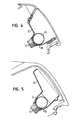
- FIG. 4 schematically shows an airbag module according to a first variant of the invention.
- the housing 10 is designed here with a trough-shaped receiving portion 26 for the gas generator 14. Since the gas generator 14 can be supported over a large area on the inside of the housing 10, the gas generator contributes significantly to the structural strength of the entire housing 10.
- FIG. 5 shows a second variant of the invention. The difference from the first variant is that the trough-shaped receiving portion 26 is made deeper.
Landscapes
- Engineering & Computer Science (AREA)
- Mechanical Engineering (AREA)
- Physics & Mathematics (AREA)
- Fluid Mechanics (AREA)
- Air Bags (AREA)
Description
- Die Erfindung betrifft ein Gassack-Modul und insbesondere ein Gassack-Modul für einen Beifahrer eines Fahrzeugs.
- Übliche Gassack-Module haben einen allgemein zylindrischen Gasgenerator, mindestens einen Zünder und ein Gehäuse, an dem der Gasgenerator befestigt ist. Ein solches Gassack-Modul soll einen minimalen Bauraum erfordern und ein geringes Gewicht aufweisen. Außerdem soll es einen einfachen Aufbau haben, um mit geringen Kosten hergestellt werden zu können. Schließlich sollen geringe Leckage-Verluste beim Aufblasen des Gassacks auftreten, um einen möglichst hohen Wirkungsgrad zu erzielen.
- Die Aufgabe der Erfindung besteht darin, ein kostengünstiges Gassack-Modul der eingangs genannten Art zu schaffen, welches die genannten Anforderungen erfüllt.
- Dokument EP 1396396 A1 ist ein Dokument gemäß Artikel 54(3) EPÜ und offenbart ein Gassack-Modul mit einem zylindrischen Gasgenerator, mindestens einem Zünder und einer Halteplatte, an der der Gasgenerator befestigt ist, wobei der Zünder sich radial aus dem Gasgenerator herauserstreckt und an der Halteplatte befestigt ist, und wobei ein Gassack vorgesehen ist, der zwischen der Halteplatte und dem Gasgenerator eingeklemmt ist.
- Dokument DE 9013131 U1 offenbart ein Gassackmodul gemäß dem Oberbegriff des unabhängigen Anspruchs 1.
- Zu diesem Zweck ist erfindungsgemäß ein Gassack-Modul mit einem allgemein zylindrischen Gasgenerator geschaffen, mindestens einem Zünder und einem Gehäuse, an dem der Gasgenerator befestigt ist, wobei der Zünder sich radial aus dem Gasgenerator herauserstreckt und am Gehäuse befestigt ist, wobei ein Gassack vorgesehen ist, der zwischen dem Gehäuse und dem Gasgenerator eingeklemmt ist, und wobei das Gehäuse einen trogförmigen Aufnahmeabschnitt für den Gasgenerator aufweist. Die Erfindung beruht auf dem Grundgedanken, zur Befestigung des Gasgenerators am Gehäuse den Zünder zu verwenden. Auf diese Weise ergibt sich zum einen ein einfacher Aufbau, da auf die ansonsten üblichen Befestigungsbleche etc. verzichtet werden kann; zur Befestigung des Gasgenerators im Gehäuse wird ein ohnehin vorhandenes Bauteil verwendet.
- Dieses braucht nur mit geringem Aufwand so ausgestaltet zu werden, daß es zur Befestigung geeignet ist. Zum anderen ergeben sich sehr geringe Leckage-Verluste, da der Zünder unmittelbar von außerhalb des Gehäuses angeschlossen werden kann; es sind keine Durchlässe für Kabel etc. erforderlich, die im Stand der Technik für einen vollständig innerhalb des Gehäuses angeordneten Zünder notwendig waren. Ein weiterer Vorteil besteht darin, daß der Gasgenerator so in das Modul integriert werden kann, daß die Strukturfestigkeit des Gasgenerators ein relevanter Bestandteil der mechanischen Bauteilfestigkeit des gesamten Gassack-Moduls wird. Schließlich kann, da der Gassack direkt vom Gasgenerator am Gehäuse festgespannt wird, auf die ansonsten üblichen Einlegeteile verzichtet werden, die zur Befestigung des Gassacks am Gehäuse verwendet werden. Es ergibt sich also ein besonders einfacher Aufbau mit einer geringen Anzahl von Bauteilen.
- Zur Befestigung des Zünders am Gehäuse kann der Zünder mit einer Halte-Geometrie versehen sein, mittels der er am Gehäuse arretiert ist, so daß der Gasgenerator fest mit dem Gehäuse verbunden ist. Als Halte-Geometrie kann insbesondere ein Außengewinde verwendet werden, auf das eine Mutter aufgeschraubt wird, die außerhalb des Gehäuses liegt und auf diese Weise den Gasgenerator fest mit dem Gehäuse verbindet. Es ist auch möglich, daß als Halte-Geometrie eine Nut verwendet wird, in die ein Haltering eingesetzt wird.
- Vorteilhafte Ausgestaltungen der Erfindung ergeben sich aus den Unteransprüchen.
- Die Erfindung wird nachfolgend anhand einer bevorzugten Ausführungsform beschrieben, die in den beigefügten Zeichnungen dargestellt ist. In diesen zeigen:
- Figur 1 eine perspektivische Explosionsansicht eines Gassack-Moduls, das allgemein zur Erläuterung dient;
- Figur 2 eine perspektivische Unteransicht des montierten Gassack-Moduls von Figur 1;
- Figur 3 eine Schnittansicht durch das Gassack-Modul von Figur 1;
- Figur 4 in einem schematischen Schnitt ein erfindungsgemäßes Gassack-Modul gemäß einer ersten Variante; und
- Figur 5 in einem schematischen Schnitt ein erfindungsgemäßes Gassack-Modul gemäß einer zweiten Variante.
- In den Figuren 1 bis 3 ist ein Gassack-Modul gezeigt, das ein Gehäuse 10 aufweist. Das Gehäuse 10 dient zur Aufnahme eines gefalteten Gassacks 12 sowie eines Gasgenerators 14. Der Gasgenerator, der hier als zylindrischer Rohrgasgenerator ausgeführt ist, kann nach Aktivierung ein Druckgas bereitstellen, mittels dem der Gassack 12 in an sich bekannter Weise entfaltet werden kann. Das Gehäuse 10 kann aus Blech bestehen und dient zum einen als Aufnahme für die übrigen Bauteile des Gassack-Moduls und ermöglicht zum anderen die Befestigung des Gassack-Moduls in einem Fahrzeug.
- Der Gasgenerator 14 ist mit zwei Zündern 16 versehen, die bezüglich der Mittelachse des Gasgenerators 14 radial angeordnet sind. Jeder der Zünder ist einer eigenen gaserzeugenden Ladung zugeordnet; beim Gasgenerator handelt es sich um einen 2-stufigen Gasgenerator. Es kann aber auch ein Gasgenerator mit mehr als 2 Stufen verwendet werden.
- Das Gehäuse 10 ist mit zwei Öffnungen 18 versehen, durch die sich die außerhalb des Gasgenerators 14 befindenden Abschnitte der Zünder 16 aus dem Gehäuse herauserstrecken. Diese außerhalb des Gehäuses liegenden Abschnitte der Zünder 16 sind jeweils mit einer Halte-Geometrie 18 versehen, die bei der in den Figuren 1 bis 3 gezeigten Ausführungsform ein Außengewinde ist. Auf das Außengewinde kann jeweils eine Mutter 22 aufgeschraubt werden.
- Wie in Figur 3 zu sehen ist, ist der Gasgenerator 14 im Inneren des Gassacks 12 angeordnet. Der Gassack 12 wird, wenn der Gasgenerator im Gehäuse 10 angeordnet ist und die Muttern 22 festgezogen werden, zwischen dem Gasgenerator 14 und dem Gehäuse 10 eingeklemmt, so daß er dort fest fixiert ist.
- Wie in Figur 2 zu sehen ist, sind die Zünder 16 auf ihrem vom Gasgenerator 14 abgewandten, freien Ende mit jeweils einem Steckanschluß 24 versehen, über die die beiden Gasgeneratoren an eine Zündeinrichtung angeschlossen werden können. Es ist zu erkennen, daß kein separater Durchgang für eine Leitung oder ähnliches in das Innere des Gassack-Moduls erforderlich ist. Auf diese Weise ergibt sich eine besonders hohe Gasdichtigkeit.
- In Figur 4 ist schematisch ein Gassack-Modul gemäß einer ersten Variante der Erfindung gezeigt. Das Gehäuse 10 ist hier mit einem trogförmigen Aufnahmeabschnitt 26 für den Gasgenerator 14 ausgeführt. Da sich der Gasgenerator 14 großflächig an der Innenseite des Gehäuses 10 abstützen kann, trägt der Gasgenerator entscheidend zur Strukturfestigkeit des gesamten Gehäuses 10 bei.
- In Figur 5 ist eine zweite Variante der Erfindung gezeigt. Der Unterschied zur ersten Variante besteht darin, daß der trogförmige Aufnahmeabschnitt 26 tiefer ausgeführt ist.
Claims (6)
- Gassack-Modul mit einem allgemein zylindrischen Gasgenerator (14), mindestens einem Zünder (16) und einem Gehäuse (10), an dem der Gasgenerator (14) befestigt ist, wobei der Zünder (16) sich radial aus dem Gasgenerator (14) herauserstreckt und am Gehäuse (10) befestigt ist, wobei ein Gassack (12) vorgesehen ist, dadurch gekennzeichnet, dass der Gassak zwischen dem Gehause (10) und dem Gasgenerator (14) eingeklemmt ist, und wobei das Gehäuse (10) einen trogförmigen Aufnahmeabschnitt (26) für den Gasgenerator (14) aufweist.
- Gassack-Modul nach Anspruch 1, dadurch gekennzeichnet, daß der Zünder (16) sich durch eine Öffnung (18) im Gehäuse (10) aus diesem herauserstreckt.
- Gassack-Modul nach einem der Ansprüche 1 und 2, dadurch gekennzeichnet, daß der Zünder (16) mit einer Halte-Geometrie (20) versehen ist, mittels der er am Gehäuse (10) arretiert ist, so daß der Gasgenerator fest mit dem Gehäuse verbunden ist.
- Gassack-Modul nach Anspruch 3, dadurch gekennzeichnet, daß die Halte-Geometrie (20) ein Außengewinde ist, auf das eine Mutter aufgeschraubt ist, so daß der Gasgenerator fest mit dem Gehäuse verschraubt ist.
- Gassack-Modul nach Anspruch 3, dadurch gekennzeichnet, daß die Halte-Geometrie (20) eine Nut ist, in die ein Haltering eingesetzt ist, so daß der Gasgenerator fest mit dem Gehäuse verbunden ist.
- Gassack-Modul nach einem der vorhergehenden Ansprüche, dadurch gekennzeichnet, daß der Gasgenerator (14) im Inneren des Gassacks (12) angeordnet ist.
Applications Claiming Priority (2)
| Application Number | Priority Date | Filing Date | Title |
|---|---|---|---|
| DE20306818U DE20306818U1 (de) | 2003-05-02 | 2003-05-02 | Gassack-Modul |
| DE20306818U | 2003-05-02 |
Publications (3)
| Publication Number | Publication Date |
|---|---|
| EP1473200A2 EP1473200A2 (de) | 2004-11-03 |
| EP1473200A3 EP1473200A3 (de) | 2004-12-22 |
| EP1473200B1 true EP1473200B1 (de) | 2006-09-06 |
Family
ID=28051456
Family Applications (1)
| Application Number | Title | Priority Date | Filing Date |
|---|---|---|---|
| EP04009611A Expired - Lifetime EP1473200B1 (de) | 2003-05-02 | 2004-04-22 | Gassack-Modul |
Country Status (5)
| Country | Link |
|---|---|
| US (1) | US7325823B2 (de) |
| EP (1) | EP1473200B1 (de) |
| JP (1) | JP5100957B2 (de) |
| DE (2) | DE20306818U1 (de) |
| ES (1) | ES2271731T3 (de) |
Families Citing this family (9)
| Publication number | Priority date | Publication date | Assignee | Title |
|---|---|---|---|---|
| DE10347697A1 (de) * | 2003-10-14 | 2005-05-19 | Trw Occupant Restraint Systems Gmbh & Co. Kg | Gasgenerator |
| DE202004013302U1 (de) * | 2004-08-25 | 2005-01-20 | Trw Automotive Gmbh | Gassack-Modul |
| DE202004017428U1 (de) | 2004-11-10 | 2005-01-27 | Trw Airbag Systems Gmbh | Gasgenerator und Gassackmodul |
| DE102006041628A1 (de) * | 2005-09-13 | 2007-04-19 | Neumayer Tekfor Holding Gmbh | Brennkammer sowie Verfahren zur Herstellung |
| DE102009039146A1 (de) * | 2009-08-27 | 2011-03-03 | GM Global Technology Operations, Inc., Detroit | Airbageinrichtung mit einem kraftfahrzeugseitigen Tragteil und einem an dem Tragteil befestigten Airbagmodul |
| US8454050B2 (en) * | 2010-03-19 | 2013-06-04 | Toyoda Gosei Co. Ltd. | Airbag housing |
| DE102012019872A1 (de) * | 2012-10-10 | 2014-04-10 | Trw Airbag Systems Gmbh | Gasgeneratorbefestigung |
| JP6350343B2 (ja) * | 2015-03-06 | 2018-07-04 | 豊田合成株式会社 | エアバッグ装置 |
| DE102016108516B4 (de) * | 2016-05-09 | 2018-02-08 | Autoliv Development Ab | Airbaggehäuse für ein Airbagmodul |
Family Cites Families (33)
| Publication number | Priority date | Publication date | Assignee | Title |
|---|---|---|---|---|
| US3787074A (en) * | 1971-05-28 | 1974-01-22 | Allied Chem | Multiple pyro system |
| US3891233A (en) * | 1974-06-20 | 1975-06-24 | Allied Chem | Inflator seal |
| JPS581333B2 (ja) * | 1978-03-02 | 1983-01-11 | 日産自動車株式会社 | 燃焼器 |
| US4153273A (en) | 1978-04-14 | 1979-05-08 | General Motors Corporation | Occupant restraint cushion system |
| JPS54155536A (en) * | 1978-05-29 | 1979-12-07 | Nippon Oil & Fats Co Ltd | Gas generator |
| US4711466A (en) * | 1986-06-27 | 1987-12-08 | Breed Corporation | Method and apparatus for gas generator initiation from external sensor |
| DE3742656A1 (de) | 1987-05-22 | 1988-12-08 | Dynamit Nobel Ag | Gaserzeuger fuer einen airbag |
| US4796912A (en) * | 1987-11-12 | 1989-01-10 | Morton Thiokol, Inc. | Elongate gas generator for inflating vehicle inflatable restraint cushions |
| DE3832120C3 (de) * | 1988-09-21 | 1997-03-13 | Temic Bayern Chem Airbag Gmbh | Gasgenerator |
| DE3909841A1 (de) * | 1989-03-25 | 1990-09-27 | Dynamit Nobel Ag | Gasgenerator fuer einen airbag mit einem schutzueberzug |
| DE4019677A1 (de) * | 1990-06-20 | 1992-01-09 | Bayern Chemie Gmbh Flugchemie | Airbagsystem |
| DE9013131U1 (de) * | 1990-09-15 | 1990-11-22 | Bayern-Chemie Gesellschaft Fuer Flugchemische Antriebe Mbh, 8261 Aschau, De | |
| JPH04283148A (ja) * | 1990-11-28 | 1992-10-08 | Dynamit Nobel Ag | ガス発生器 |
| JP3115381B2 (ja) * | 1990-11-28 | 2000-12-04 | デイナミート ノーベル アクチエンゲゼルシヤフト | エアバッグ用のガス発生器、特に管型ガス発生器 |
| US5100174A (en) * | 1990-12-18 | 1992-03-31 | Trw, Inc. | Auto ignition package for an air bag inflator |
| DE4102615A1 (de) * | 1991-01-30 | 1992-08-06 | Bayern Chemie Gmbh Flugchemie | Gasgenerator |
| US5611566A (en) * | 1992-08-20 | 1997-03-18 | Temic Bayern-Chemie Airbag Gmbh | Gas generator for a safety system for protecting occupants in motor vehicles |
| US5542701A (en) * | 1992-10-26 | 1996-08-06 | Alliedsignal Inc. | Wire track with integral sealing mechanism and inflator |
| US5458364A (en) * | 1994-08-22 | 1995-10-17 | Morton International, Inc. | Inflator secured in diffuser housing of airbag module assembly by locking end cap |
| JPH08230597A (ja) * | 1994-12-26 | 1996-09-10 | Toyoda Gosei Co Ltd | エアバッグ装置 |
| JPH08207692A (ja) * | 1995-01-31 | 1996-08-13 | Nippon Plast Co Ltd | エアバッグ装置 |
| JPH08301042A (ja) * | 1995-05-08 | 1996-11-19 | Tokai Rika Co Ltd | エアバッグ装置 |
| US5590900A (en) * | 1995-07-21 | 1997-01-07 | Avibank Mfg., Inc. | Air bag mounting system |
| JPH0958397A (ja) | 1995-08-21 | 1997-03-04 | Daicel Chem Ind Ltd | ガス発生器 |
| US5667241A (en) * | 1995-10-17 | 1997-09-16 | Morton International, Inc. | Seat mounted side impact airbags |
| US5762368A (en) * | 1996-06-20 | 1998-06-09 | Trw Vehicle Safety Systems Inc. | Initiator for air bag inflator |
| US5687988A (en) * | 1996-07-17 | 1997-11-18 | Morton International, Inc. | Airbag cushion and airbag inflator retention device |
| US5823566A (en) * | 1996-10-16 | 1998-10-20 | Alliedsignal Inc. | Air bag module with deployment flap |
| US5803488A (en) * | 1997-06-13 | 1998-09-08 | Alliedsignal Inc. | Inflator retainer and air bag module |
| DE19739375B4 (de) * | 1997-09-09 | 2005-07-28 | Welz Industrieprodukte Gmbh | Öffnungsvorrichtung für einen Gasdruckbehälter eines Airbags |
| JP3577208B2 (ja) * | 1997-12-09 | 2004-10-13 | トヨタ自動車株式会社 | 助手席用エアバッグ装置 |
| US6176511B1 (en) * | 1998-10-07 | 2001-01-23 | Trw Inc. | Air bag module |
| DE10240640B3 (de) | 2002-09-03 | 2004-02-12 | Trw Airbag Systems Gmbh & Co. Kg | Verfahren zum Herstellung eines Gasgeneratorgehäuseteils, Gasgenerator mit diesem Gehäuseteil sowie Gassackmodul |
-
2003
- 2003-05-02 DE DE20306818U patent/DE20306818U1/de not_active Expired - Lifetime
-
2004
- 2004-04-22 DE DE502004001381T patent/DE502004001381D1/de not_active Expired - Lifetime
- 2004-04-22 ES ES04009611T patent/ES2271731T3/es not_active Expired - Lifetime
- 2004-04-22 EP EP04009611A patent/EP1473200B1/de not_active Expired - Lifetime
- 2004-04-29 US US10/834,471 patent/US7325823B2/en active Active
- 2004-05-06 JP JP2004137307A patent/JP5100957B2/ja not_active Expired - Lifetime
Also Published As
| Publication number | Publication date |
|---|---|
| JP2004331059A (ja) | 2004-11-25 |
| DE502004001381D1 (de) | 2006-10-19 |
| US20040217579A1 (en) | 2004-11-04 |
| US7325823B2 (en) | 2008-02-05 |
| EP1473200A2 (de) | 2004-11-03 |
| ES2271731T3 (es) | 2007-04-16 |
| EP1473200A3 (de) | 2004-12-22 |
| JP5100957B2 (ja) | 2012-12-19 |
| DE20306818U1 (de) | 2003-09-11 |
Similar Documents
| Publication | Publication Date | Title |
|---|---|---|
| EP1851830B1 (de) | Verbindungssystem, insbesondere elektrisches verbindungssystem | |
| EP2627541B1 (de) | Gasgenerator und gassackmodul | |
| DE60310621T2 (de) | Befestigungsverfahren und Struktur eines Gasgenerators und Luftsackanordnung | |
| EP1473200B1 (de) | Gassack-Modul | |
| DE102006013990A1 (de) | Befestigungsanordnung in einem Airbagmodul | |
| DE102011107210A1 (de) | Halteeinrichtung zur Halterung einer Baueinheit an einem Kraftwagen | |
| EP2043892B1 (de) | Rastvorrichtung zur fixierung eines an einem halterahmen befestigten gassacks in einem gehäuse eines beifahrerairbagmoduls | |
| DE102004056249A1 (de) | Schutzvorrichtung für Kraftfahrzeuge | |
| EP2698295B1 (de) | Längenverstellbares Teleskoprohr, Stützwinde und Montageverfahren | |
| EP1532024B1 (de) | Airbagmodul mit gasgenerator | |
| DE202005010864U1 (de) | Airbagmodul zum Einbau in ein Kraftfahrzeug | |
| DE102017220724A1 (de) | Energiespeicher für ein Kraftfahrzeug sowie entsprechendes Kraftfahrzeug | |
| DE102007053101B4 (de) | Gasgenerator und Baugruppe mit einem Gasgenerator | |
| EP2176094B1 (de) | Airbagmodul | |
| EP2421726B1 (de) | Gassackmodul für ein fahrzeuginsassen-rückhaltesystem und verfahren zu dessen herstellung | |
| EP0876269B1 (de) | Antriebsvorrichtung für ein insassen-rückhaltesystem | |
| EP2089254B1 (de) | Gassackbefestigung in einem airbagmodul | |
| EP2190699B1 (de) | Brennkammerbaueinheit für ein airbagmodul | |
| DE10044146A1 (de) | Leuchte für Fahrzeuge | |
| DE10005667B4 (de) | Gasgenerator, Behälter hierfür und Verfahren zum Herstellen des Behälters | |
| EP0822124A1 (de) | Gassack-Modul für ein Fahrzeuginsassen-Rückhaltesystem | |
| EP1088711A2 (de) | Beifahrer-Airbagmodul für Kraftfahrzeuge | |
| EP1403147A2 (de) | Baugruppe aus Gasgenerator und Generatorträger | |
| EP2060422B1 (de) | Rolloeinrichtung für ein Kraftfahrzeug | |
| DE202004013302U1 (de) | Gassack-Modul |
Legal Events
| Date | Code | Title | Description |
|---|---|---|---|
| PUAI | Public reference made under article 153(3) epc to a published international application that has entered the european phase |
Free format text: ORIGINAL CODE: 0009012 |
|
| AK | Designated contracting states |
Kind code of ref document: A2 Designated state(s): AT BE BG CH CY CZ DE DK EE ES FI FR GB GR HU IE IT LI LU MC NL PL PT RO SE SI SK TR |
|
| AX | Request for extension of the european patent |
Extension state: AL HR LT LV MK |
|
| PUAL | Search report despatched |
Free format text: ORIGINAL CODE: 0009013 |
|
| AK | Designated contracting states |
Kind code of ref document: A3 Designated state(s): AT BE BG CH CY CZ DE DK EE ES FI FR GB GR HU IE IT LI LU MC NL PL PT RO SE SI SK TR |
|
| AX | Request for extension of the european patent |
Extension state: AL HR LT LV MK |
|
| 17P | Request for examination filed |
Effective date: 20050427 |
|
| AKX | Designation fees paid |
Designated state(s): DE ES FR IT |
|
| GRAP | Despatch of communication of intention to grant a patent |
Free format text: ORIGINAL CODE: EPIDOSNIGR1 |
|
| GRAS | Grant fee paid |
Free format text: ORIGINAL CODE: EPIDOSNIGR3 |
|
| GRAA | (expected) grant |
Free format text: ORIGINAL CODE: 0009210 |
|
| AK | Designated contracting states |
Kind code of ref document: B1 Designated state(s): DE ES FR IT |
|
| PG25 | Lapsed in a contracting state [announced via postgrant information from national office to epo] |
Ref country code: IT Free format text: LAPSE BECAUSE OF FAILURE TO SUBMIT A TRANSLATION OF THE DESCRIPTION OR TO PAY THE FEE WITHIN THE PRESCRIBED TIME-LIMIT;WARNING: LAPSES OF ITALIAN PATENTS WITH EFFECTIVE DATE BEFORE 2007 MAY HAVE OCCURRED AT ANY TIME BEFORE 2007. THE CORRECT EFFECTIVE DATE MAY BE DIFFERENT FROM THE ONE RECORDED. Effective date: 20060906 |
|
| REF | Corresponds to: |
Ref document number: 502004001381 Country of ref document: DE Date of ref document: 20061019 Kind code of ref document: P |
|
| ET | Fr: translation filed | ||
| REG | Reference to a national code |
Ref country code: ES Ref legal event code: FG2A Ref document number: 2271731 Country of ref document: ES Kind code of ref document: T3 |
|
| PLBE | No opposition filed within time limit |
Free format text: ORIGINAL CODE: 0009261 |
|
| STAA | Information on the status of an ep patent application or granted ep patent |
Free format text: STATUS: NO OPPOSITION FILED WITHIN TIME LIMIT |
|
| 26N | No opposition filed |
Effective date: 20070607 |
|
| REG | Reference to a national code |
Ref country code: ES Ref legal event code: FD2A Effective date: 20070423 |
|
| PGRI | Patent reinstated in contracting state [announced from national office to epo] |
Ref country code: IT Effective date: 20080601 |
|
| PG25 | Lapsed in a contracting state [announced via postgrant information from national office to epo] |
Ref country code: ES Free format text: LAPSE BECAUSE OF NON-PAYMENT OF DUE FEES Effective date: 20070423 |
|
| REG | Reference to a national code |
Ref country code: FR Ref legal event code: PLFP Year of fee payment: 13 |
|
| REG | Reference to a national code |
Ref country code: FR Ref legal event code: PLFP Year of fee payment: 14 |
|
| REG | Reference to a national code |
Ref country code: FR Ref legal event code: PLFP Year of fee payment: 15 |
|
| PGFP | Annual fee paid to national office [announced via postgrant information from national office to epo] |
Ref country code: DE Payment date: 20190430 Year of fee payment: 16 |
|
| REG | Reference to a national code |
Ref country code: DE Ref legal event code: R119 Ref document number: 502004001381 Country of ref document: DE |
|
| PG25 | Lapsed in a contracting state [announced via postgrant information from national office to epo] |
Ref country code: DE Free format text: LAPSE BECAUSE OF NON-PAYMENT OF DUE FEES Effective date: 20201103 |
|
| PGFP | Annual fee paid to national office [announced via postgrant information from national office to epo] |
Ref country code: FR Payment date: 20230309 Year of fee payment: 20 |
|
| PGFP | Annual fee paid to national office [announced via postgrant information from national office to epo] |
Ref country code: IT Payment date: 20230310 Year of fee payment: 20 |
|
| P01 | Opt-out of the competence of the unified patent court (upc) registered |
Effective date: 20230628 |